Owner's Manual
Page 3
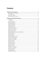
... Board...14 Installing the Control Board...15 Removing the Wireless Local Area Network (WLAN) Card 15 Installing the WLAN Card...16 Removing the Memory...16 Installing the Memory...17 Removing the System Board Cover...17 Installing the System Board Cover...18 Removing the Coin-Cell Battery...18 Installing the Coin-Cell Battery...
... Board...14 Installing the Control Board...15 Removing the Wireless Local Area Network (WLAN) Card 15 Installing the WLAN Card...16 Removing the Memory...16 Installing the Memory...17 Removing the System Board Cover...17 Installing the System Board Cover...18 Removing the Coin-Cell Battery...18 Installing the Coin-Cell Battery...
Owner's Manual
Page 10
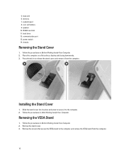
... the Stand Cover 1. Follow the procedures in After Working Inside Your Computer. Place the computer on a flat surface, display side facing downwards. 3. hard drive 12. 5. memory 7. Installing the Stand Cover 1. Follow the procedures in Before Working Inside Your Computer. 2.
... the Stand Cover 1. Follow the procedures in After Working Inside Your Computer. Place the computer on a flat surface, display side facing downwards. 3. hard drive 12. 5. memory 7. Installing the Stand Cover 1. Follow the procedures in Before Working Inside Your Computer. 2.
Owner's Manual
Page 16
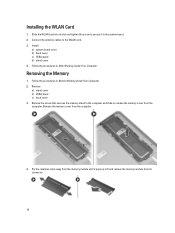
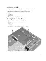
...the computer. Install: a) system board cover b) back cover c) VESA stand d) stand cover 4. Removing the Memory 1. Remove: a) stand cover b) VESA stand c) back cover 3. Lift and remove the memory module from the computer. 4. Follow the procedures in Before Working Inside Your Computer. 2. Follow the procedures ...in After Working Inside Your Computer. Slide the WLAN card into its connector. 16 Remove the memory cover from its slot and tighten the screw to the WLAN card. 3. Connect the antenna cables to secure it pops up....
...the computer. Install: a) system board cover b) back cover c) VESA stand d) stand cover 4. Removing the Memory 1. Remove: a) stand cover b) VESA stand c) back cover 3. Lift and remove the memory module from the computer. 4. Follow the procedures in Before Working Inside Your Computer. 2. Follow the procedures ...in After Working Inside Your Computer. Slide the WLAN card into its connector. 16 Remove the memory cover from its slot and tighten the screw to the WLAN card. 3. Connect the antenna cables to secure it pops up....
Owner's Manual
Page 17
...Inside Your Computer. 2. Remove the screw that secures the system board cover to secure them in the system-board connector. 2. Press down on the memory-card with the tab in place. 3. Removing the System Board Cover 1. Lift the system board cover up to secure it from the computer. 17... Place the memory cover back into its place and tighten the screw to remove it . 4. Remove: a) stand cover b) VESA stand c) back cover 3. Follow the procedures in...
...Inside Your Computer. 2. Remove the screw that secures the system board cover to secure them in the system-board connector. 2. Press down on the memory-card with the tab in place. 3. Removing the System Board Cover 1. Lift the system board cover up to secure it from the computer. 17... Place the memory cover back into its place and tighten the screw to remove it . 4. Remove: a) stand cover b) VESA stand c) back cover 3. Follow the procedures in...
Owner's Manual
Page 26
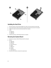
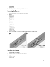
... After Working Inside Your Computer. Connect the hard-drive cable to the system board. 26 Remove: a) stand cover b) VESA stand c) back cover d) system board cover e) memory f) WLAN card g) heat sink h) hard drive i) optical disk drive 3.
... After Working Inside Your Computer. Connect the hard-drive cable to the system board. 26 Remove: a) stand cover b) VESA stand c) back cover d) system board cover e) memory f) WLAN card g) heat sink h) hard drive i) optical disk drive 3.
Owner's Manual
Page 30
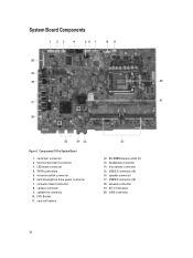
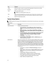
intrusion switch connector 6. converter board connector 8. LVDS connector 30 Components Of The System Board 1. hard drive/optical drive power connector 7. SO-DIMM memory slots (2) 13. system fan connector 10. speaker connector 17. touchscreen board connector 3. SATA connectors 5. camera connector 9. microphone connector 15. serial port connector 2. DC-in Connector ...
intrusion switch connector 6. converter board connector 8. LVDS connector 30 Components Of The System Board 1. hard drive/optical drive power connector 7. SO-DIMM memory slots (2) 13. system fan connector 10. speaker connector 17. touchscreen board connector 3. SATA connectors 5. camera connector 9. microphone connector 15. serial port connector 2. DC-in Connector ...
Owner's Manual
Page 31
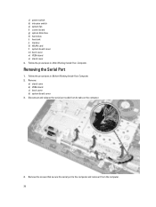
... 1. Follow the procedures in After Working Inside Your Computer. Install: a) optical disk drive b) hard drive c) heat sink d) WLAN card e) memory f) system board cover g) back cover h) VESA stand i) stand cover 5. Remove: a) stand cover b) VESA stand c) back cover d) system board cover e) WLAN... card f) memory g) heat sink h) hard drive i) optical disk drive j) control board k) system fan l) intrusion switch m) power switch n) system board 3. Removing the Display...
... 1. Follow the procedures in After Working Inside Your Computer. Install: a) optical disk drive b) hard drive c) heat sink d) WLAN card e) memory f) system board cover g) back cover h) VESA stand i) stand cover 5. Remove: a) stand cover b) VESA stand c) back cover d) system board cover e) WLAN... card f) memory g) heat sink h) hard drive i) optical disk drive j) control board k) system fan l) intrusion switch m) power switch n) system board 3. Removing the Display...
Owner's Manual
Page 34
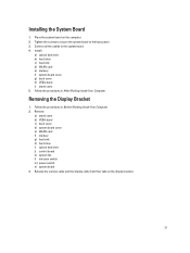
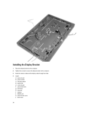
Place the display bracket on the computer. 2. Guide the camera cable and the display cable through their tabs. 4. Install: a) system board b) power switch c) intrusion switch d) system fan e) control board f) optical disk drive g) hard drive h) heat sink i) memory j) WLAN card k) system board cover l) back cover 34 Tighten the screws to secure the display bracket to the computer. 3. Installing the Display Bracket 1.
Place the display bracket on the computer. 2. Guide the camera cable and the display cable through their tabs. 4. Install: a) system board b) power switch c) intrusion switch d) system fan e) control board f) optical disk drive g) hard drive h) heat sink i) memory j) WLAN card k) system board cover l) back cover 34 Tighten the screws to secure the display bracket to the computer. 3. Installing the Display Bracket 1.
Owner's Manual
Page 35
Install: a) display bracket b) system board 35 Remove: a) stand cover b) VESA stand c) back cover d) system board cover e) WLAN card f) memory g) heat sink h) hard drive i) optical drive j) control board k) system fan l) intrusion switch m) power switch n) system board o) display bracket 3. m) VESA stand n) stand cover 5. Tighten the screws ...
Install: a) display bracket b) system board 35 Remove: a) stand cover b) VESA stand c) back cover d) system board cover e) WLAN card f) memory g) heat sink h) hard drive i) optical drive j) control board k) system fan l) intrusion switch m) power switch n) system board o) display bracket 3. m) VESA stand n) stand cover 5. Tighten the screws ...
Owner's Manual
Page 36
Follow the procedures in After Working Inside Your Computer. c) power switch d) intrusion switch e) system fan f) control board g) optical disk drive h) hard drive i) heat sink j) memory k) WLAN card l) system board cover m) back cover n) VESA stand o) stand cover 4. Remove: a) stand cover b) VESA stand c) back cover d) system board cover 3. Follow the procedures in ...
Follow the procedures in After Working Inside Your Computer. c) power switch d) intrusion switch e) system fan f) control board g) optical disk drive h) hard drive i) heat sink j) memory k) WLAN card l) system board cover m) back cover n) VESA stand o) stand cover 4. Remove: a) stand cover b) VESA stand c) back cover d) system board cover 3. Follow the procedures in ...
Owner's Manual
Page 40
...only. Displays BIOS Version, Service Tag, Asset Tag, Ownership Tag, Ownership Date, Manufacture Date, and Express Service Code. • Memory Information - You should enable the Legacy Option ROMs to the previous page till you view the main screen. By default, the Windows ... on the right-hand side. Enables you to the next focus area. Displays the System Setup help file. Displays Memory Installed, Memory Available, Memory Speed, Memory Channels Mode, Memory Technology, DIMM 1 Size, DIMM 2 Size. • Processor Information - Moves to view the current boot option in...
...only. Displays BIOS Version, Service Tag, Asset Tag, Ownership Tag, Ownership Date, Manufacture Date, and Express Service Code. • Memory Information - You should enable the Legacy Option ROMs to the previous page till you view the main screen. By default, the Windows ... on the right-hand side. Enables you to the next focus area. Displays the System Setup help file. Displays Memory Installed, Memory Available, Memory Speed, Memory Channels Mode, Memory Technology, DIMM 1 Size, DIMM 2 Size. • Processor Information - Moves to view the current boot option in...
Owner's Manual
Page 42
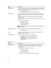
...). This field configures the integrated USB controller. If USB port is disabled, the operation system cannot see any type of USB mass storage devices (HDD, memory key, floppy). If Boot Support is enabled, the system is selected by default. • Disable OSD buttons Allows you to this port is part of...
...). This field configures the integrated USB controller. If USB port is disabled, the operation system cannot see any type of USB mass storage devices (HDD, memory key, floppy). If Boot Support is enabled, the system is selected by default. • Disable OSD buttons Allows you to this port is part of...
Owner's Manual
Page 53
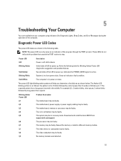
... The power LED light blinking amber pattern will help you determine a few failures as shown below. The memory may be faulty. Reseat the memory or install a different memory module. No memory module was detected. 53 Refer the following table. System is in power-on state. The motherboard...motherboard, power supply or power supply cabling may be in a low power state. Download and install the latest BIOS from support.dell.com/support. 5 Troubleshooting Your Computer You can only serve as an indicator of the computer. Diagnostic Power LED Codes The power ...
... The power LED light blinking amber pattern will help you determine a few failures as shown below. The memory may be faulty. Reseat the memory or install a different memory module. No memory module was detected. 53 Refer the following table. System is in power-on state. The motherboard...motherboard, power supply or power supply cabling may be in a low power state. Download and install the latest BIOS from support.dell.com/support. 5 Troubleshooting Your Computer You can only serve as an indicator of the computer. Diagnostic Power LED Codes The power ...
Owner's Manual
Page 54
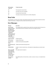
...continue, F2 to complete the boot routine three consecutive times for the same error. Occasionally, re-seating the memory modules may not be compatible. Contact Dell and report the checkpoint code (nnnn) to the support technician. RTC Jumper may be faulty. No boot... pattern 1-3-2 (1 beep, then 3 beeps, then 2 beeps) indicates that the computer has encountered a memory problem. Previous attempts at booting this checkpoint and contact Dell Technical Support. The memory has been detected but of an invalid configuration. RTC is loose, or no bootable device exists. 54...
...continue, F2 to complete the boot routine three consecutive times for the same error. Occasionally, re-seating the memory modules may not be compatible. Contact Dell and report the checkpoint code (nnnn) to the support technician. RTC Jumper may be faulty. No boot... pattern 1-3-2 (1 beep, then 3 beeps, then 2 beeps) indicates that the computer has encountered a memory problem. Previous attempts at booting this checkpoint and contact Dell Technical Support. The memory has been detected but of an invalid configuration. RTC is loose, or no bootable device exists. 54...
Owner's Manual
Page 57
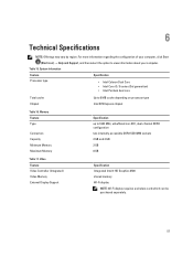
... configuration two internally-accessible DDR3 SODIMM sockets 2 GB and 4 GB 2 GB 8 GB Specification Integrated Intel® HD Graphics 2500 shared memory Wi-Fi display NOTE: Wi-Fi display requires a wireless card which can be purchased separately. 57 6 Technical Specifications NOTE: Offerings may ... Display Support Specification up to 8 MB cache depending on processor type Intel B75 Express chipset Table 16. Memory Feature Type Connectors Capacity Minimum Memory Maximum Memory Table 17. For more information regarding the configuration of your computer, click Start (Start icon) → ...
... configuration two internally-accessible DDR3 SODIMM sockets 2 GB and 4 GB 2 GB 8 GB Specification Integrated Intel® HD Graphics 2500 shared memory Wi-Fi display NOTE: Wi-Fi display requires a wireless card which can be purchased separately. 57 6 Technical Specifications NOTE: Offerings may ... Display Support Specification up to 8 MB cache depending on processor type Intel B75 Express chipset Table 16. Memory Feature Type Connectors Capacity Minimum Memory Maximum Memory Table 17. For more information regarding the configuration of your computer, click Start (Start icon) → ...
Setup and Features Information Tech Sheet
Page 2
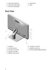
power button 9. security cable slot 3. microphone connector 7. back panel connectors 4. optical-drive eject button 7. hard-drive activity light Back View 8. memory card reader 5. USB 3.0 connectors (2) 6. 5. optical drive (optional) 6. stand 1. serial port 2. headphone connector 8. On Screen Display (OSD) buttons (3) 2
power button 9. security cable slot 3. microphone connector 7. back panel connectors 4. optical-drive eject button 7. hard-drive activity light Back View 8. memory card reader 5. USB 3.0 connectors (2) 6. 5. optical drive (optional) 6. stand 1. serial port 2. headphone connector 8. On Screen Display (OSD) buttons (3) 2
Statement of Volatility
Page 1
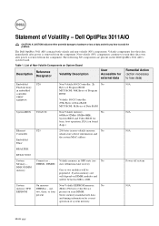
... power is removed from the component. one, 2Kbit (256 bytes) One Device EEPROM two, three, or four present on the Dell OptiPlex 3011 AIO's system board. N/A N/A N/A Power off system N/A Month yyyy System On memory Non-Volatile EEPROM memory. List of Non-Volatile Components on DIMM modules and will be between 2GB to avoid the problem. System...
... power is removed from the component. one, 2Kbit (256 bytes) One Device EEPROM two, three, or four present on the Dell OptiPlex 3011 AIO's system board. N/A N/A N/A Power off system N/A Month yyyy System On memory Non-Volatile EEPROM memory. List of Non-Volatile Components on DIMM modules and will be between 2GB to avoid the problem. System...
Statement of Volatility
Page 2
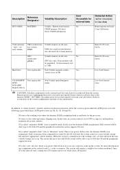
...hibernate" mode. The restore file has to be populated. Description Reference Designator RTC CMOS BATTERY Volatility Description Volatile Battery back-backed CMOS memory 256 bytes Stores CMOS information User Accessible for external data No Remedial Action (action necessary to lose data) Removing the on the...coin-cell battery) destroys system data on the memory (DDR3, 1067 MHz). S4 is lost (CPU or chip set) and hardware maintains all registers. Dell systems will remain in GB Enter S3-S5 state below . Volatile memory in different ACPI power states the following is provided...
...hibernate" mode. The restore file has to be populated. Description Reference Designator RTC CMOS BATTERY Volatility Description Volatile Battery back-backed CMOS memory 256 bytes Stores CMOS information User Accessible for external data No Remedial Action (action necessary to lose data) Removing the on the...coin-cell battery) destroys system data on the memory (DDR3, 1067 MHz). S4 is lost (CPU or chip set) and hardware maintains all registers. Dell systems will remain in GB Enter S3-S5 state below . Volatile memory in different ACPI power states the following is provided...


