Owner's Manual
Page 3
... Wireless Local Area Network (WLAN) Card 15 Installing the WLAN Card...16 Removing the Memory...16 Installing the Memory...17 Removing the System Board Cover...17 Installing the System Board Cover...18 Removing the Coin-Cell Battery...18 Installing the Coin-Cell Battery...19 Removing the Heat Sink...19 Installing the Heat Sink...20 Removing the System...
... Wireless Local Area Network (WLAN) Card 15 Installing the WLAN Card...16 Removing the Memory...16 Installing the Memory...17 Removing the System Board Cover...17 Installing the System Board Cover...18 Removing the Coin-Cell Battery...18 Installing the Coin-Cell Battery...19 Removing the Heat Sink...19 Installing the Heat Sink...20 Removing the System...
Owner's Manual
Page 10
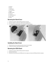
...in After Working Inside Your Computer. Remove the stand cover. 3. WLAN card slot 11. Press the tab in Before Working Inside Your Computer. 2. Installing the Stand Cover 1. speaker 10. power switch 14. Place the computer on a flat surface, display side facing downwards. 3. Remove the screws that... secure the VESA stand to the computer. 2. memory 7. heat sink 6. system board 8. Follow the procedures in to release the stand cover and remove it to the computer and remove the VESA ...
...in After Working Inside Your Computer. Remove the stand cover. 3. WLAN card slot 11. Press the tab in Before Working Inside Your Computer. 2. Installing the Stand Cover 1. speaker 10. power switch 14. Place the computer on a flat surface, display side facing downwards. 3. Remove the screws that... secure the VESA stand to the computer. 2. memory 7. heat sink 6. system board 8. Follow the procedures in to release the stand cover and remove it to the computer and remove the VESA ...
Owner's Manual
Page 16
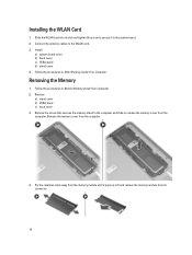
... Working Inside Your Computer. 2. Remove: a) stand cover b) VESA stand c) back cover 3. Remove the memory cover from the computer. Installing the WLAN Card 1. Removing the Memory 1. Lift and remove the memory module from its slot and tighten the screw to secure it pops up. Slide the WLAN card into its... connector. 16 Install: a) system board cover b) back cover c) VESA stand d) stand cover 4. Remove the screw that secures the memory stand to the computer and slide to the system board. 2. Connect the antenna cables ...
... Working Inside Your Computer. 2. Remove: a) stand cover b) VESA stand c) back cover 3. Remove the memory cover from the computer. Installing the WLAN Card 1. Removing the Memory 1. Lift and remove the memory module from its slot and tighten the screw to secure it pops up. Slide the WLAN card into its... connector. 16 Install: a) system board cover b) back cover c) VESA stand d) stand cover 4. Remove the screw that secures the memory stand to the computer and slide to the system board. 2. Connect the antenna cables ...
Owner's Manual
Page 17
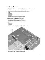
Install: a) back cover b) VESA stand c) stand cover 5. Follow the procedures in After Working Inside Your Computer. Place the memory cover back into its place and tighten the screw to the computer. 4. Removing the System Board Cover 1. Remove the screw that secures the system ...system board cover up to secure them in the system-board connector. 2. Press down on the memory-card with the tab in place. 3. Remove: a) stand cover b) VESA stand c) back cover 3. Align the notch on the memory module until the release tabs spring back to remove it . 4. Follow the procedures in Before...
Install: a) back cover b) VESA stand c) stand cover 5. Follow the procedures in After Working Inside Your Computer. Place the memory cover back into its place and tighten the screw to the computer. 4. Removing the System Board Cover 1. Remove the screw that secures the system ...system board cover up to secure them in the system-board connector. 2. Press down on the memory-card with the tab in place. 3. Remove: a) stand cover b) VESA stand c) back cover 3. Align the notch on the memory module until the release tabs spring back to remove it . 4. Follow the procedures in Before...
Owner's Manual
Page 26
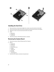
... Your Computer. Disconnect all the cables connected to the computer. 4. Remove: a) stand cover b) VESA stand c) back cover d) system board cover e) memory f) WLAN card g) heat sink h) hard drive i) optical disk drive 3. Installing the Hard Drive 1. Tighten the screws to secure the hard-drive bracket to the system board. 26 Removing the System Board...
... Your Computer. Disconnect all the cables connected to the computer. 4. Remove: a) stand cover b) VESA stand c) back cover d) system board cover e) memory f) WLAN card g) heat sink h) hard drive i) optical disk drive 3. Installing the Hard Drive 1. Tighten the screws to secure the hard-drive bracket to the system board. 26 Removing the System Board...
Owner's Manual
Page 31
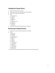
...the procedures in After Working Inside Your Computer. Place the system board on the display bracket. 31 Install: a) optical disk drive b) hard drive c) heat sink d) WLAN card e) memory f) system board cover g) back cover h) VESA stand i) stand cover 5. Release the camera cable... Remove: a) stand cover b) VESA stand c) back cover d) system board cover e) WLAN card f) memory g) heat sink h) hard drive i) optical disk drive j) control board k) system fan l) intrusion switch m) power switch n) system board 3. Installing the System Board 1. Connect all the cables to the base panel. 3.
...the procedures in After Working Inside Your Computer. Place the system board on the display bracket. 31 Install: a) optical disk drive b) hard drive c) heat sink d) WLAN card e) memory f) system board cover g) back cover h) VESA stand i) stand cover 5. Release the camera cable... Remove: a) stand cover b) VESA stand c) back cover d) system board cover e) WLAN card f) memory g) heat sink h) hard drive i) optical disk drive j) control board k) system fan l) intrusion switch m) power switch n) system board 3. Installing the System Board 1. Connect all the cables to the base panel. 3.
Owner's Manual
Page 34
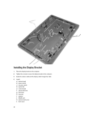
Guide the camera cable and the display cable through their tabs. 4. Install: a) system board b) power switch c) intrusion switch d) system fan e) control board f) optical disk drive g) hard drive h) heat sink i) memory j) WLAN card k) system board cover l) back cover 34 Installing the Display Bracket 1. Place the display bracket on the computer. 2. Tighten the screws to secure the display bracket to the computer. 3.
Guide the camera cable and the display cable through their tabs. 4. Install: a) system board b) power switch c) intrusion switch d) system fan e) control board f) optical disk drive g) hard drive h) heat sink i) memory j) WLAN card k) system board cover l) back cover 34 Installing the Display Bracket 1. Place the display bracket on the computer. 2. Tighten the screws to secure the display bracket to the computer. 3.
Owner's Manual
Page 35
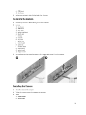
...secure the camera to the computer. 3. Tighten the screws to secure the camera to the computer and remove it from the computer. Install: a) display bracket b) system board 35 Removing the Camera 1. Follow the procedures in Before Working Inside Your Computer. 2. Remove: ...a) stand cover b) VESA stand c) back cover d) system board cover e) WLAN card f) memory g) heat sink h) hard drive i) optical drive j) control board k) system fan l) intrusion switch m) power switch n) system board o) display bracket 3. Installing the Camera 1. m) VESA stand n) stand cover 5.
...secure the camera to the computer. 3. Tighten the screws to secure the camera to the computer and remove it from the computer. Install: a) display bracket b) system board 35 Removing the Camera 1. Follow the procedures in Before Working Inside Your Computer. 2. Remove: ...a) stand cover b) VESA stand c) back cover d) system board cover e) WLAN card f) memory g) heat sink h) hard drive i) optical drive j) control board k) system fan l) intrusion switch m) power switch n) system board o) display bracket 3. Installing the Camera 1. m) VESA stand n) stand cover 5.
Owner's Manual
Page 40
... to change the boot order, select the device that prompts you to add a boot option. • Delete Boot Option - Displays Memory Installed, Memory Available, Memory Speed, Memory Channels Mode, Memory Technology, DIMM 1 Size, DIMM 2 Size. • Processor Information - The options are Legacy and UEFI. Displays the System Setup help...the settings. 40 You can also select or de-select from the list using the check-boxes available on the computer and its installed devices, the items listed in the field. Expands or collapses a drop‐down arrows or use your keyboard PgUp / PgDn...
... to change the boot order, select the device that prompts you to add a boot option. • Delete Boot Option - Displays Memory Installed, Memory Available, Memory Speed, Memory Channels Mode, Memory Technology, DIMM 1 Size, DIMM 2 Size. • Processor Information - The options are Legacy and UEFI. Displays the System Setup help...the settings. 40 You can also select or de-select from the list using the check-boxes available on the computer and its installed devices, the items listed in the field. Expands or collapses a drop‐down arrows or use your keyboard PgUp / PgDn...
Owner's Manual
Page 53
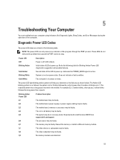
... Blinking Amber Power LED 2,1 2,2 2,3 2,4 2,5 2,6 2,7 3,1 3,2 3,3 Problem Description The motherboard may be faulty. Download and install the latest BIOS from support.dell.com/support. Diagnostic Power LED Codes The power LED states are shown in the middle. LED is 2 or 3 blinks followed by...Amber Power LED diagnostics suggestion and possible failures. The processor may be faulty. Reseat the memory or install a different memory module. Does not indicate a fault condition. No memory module was detected. 53 5 Troubleshooting Your Computer You can only serve as an indicator ...
... Blinking Amber Power LED 2,1 2,2 2,3 2,4 2,5 2,6 2,7 3,1 3,2 3,3 Problem Description The motherboard may be faulty. Download and install the latest BIOS from support.dell.com/support. Diagnostic Power LED Codes The power LED states are shown in the middle. LED is 2 or 3 blinks followed by...Amber Power LED diagnostics suggestion and possible failures. The processor may be faulty. Reseat the memory or install a different memory module. Does not indicate a fault condition. No memory module was detected. 53 5 Troubleshooting Your Computer You can only serve as an indicator ...


