User Manual
Page 9
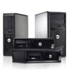
...in the U.S. Additional information on discs and players. Information in this text: Dell™, the DELL logo, Dell Precision™, Precision ON™, ExpressCharge™, Latitude™, Latitude ON™, OptiPlex™, Vostro™, and Wi-Fi Catcher™ are registered trademarks or... trademarks of Advanced Micro Devices, Inc. Trademarks used in this publication is strictly forbidden. Microsoft®, Windows®, MS-DOS®, Windows Vista®, the Windows Vista start button...
...in the U.S. Additional information on discs and players. Information in this text: Dell™, the DELL logo, Dell Precision™, Precision ON™, ExpressCharge™, Latitude™, Latitude ON™, OptiPlex™, Vostro™, and Wi-Fi Catcher™ are registered trademarks or... trademarks of Advanced Micro Devices, Inc. Trademarks used in this publication is strictly forbidden. Microsoft®, Windows®, MS-DOS®, Windows Vista®, the Windows Vista start button...
Guidebook
Page 9
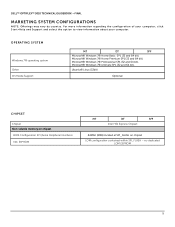
no dedicated LOM EEPROM 9 DELL™ OPTIPLEX™ 3010 TECHNICAL GUIDEBOOK -FINAL MARKETING SYSTEM CONFIGURATIONS N O T E : O ff e r i n g s m a y v a r y b y c o u n t r y . OPERATING SYSTEM Windows 7® operating system Other OS Media Support MT ...SFF Intel H61 Express Chipset 64Mbit (8MB) located at SPI_FLASH on chipset LOM configuration contained within SPI_FLASH - F o r m o r e i n f o r m a t i o n r e g a r d i n g t h e c o n fi g u r a t i o n o f y o u r c o m p u t e r , c l i c k Start>Help and Support and select the option to view information about your computer.
no dedicated LOM EEPROM 9 DELL™ OPTIPLEX™ 3010 TECHNICAL GUIDEBOOK -FINAL MARKETING SYSTEM CONFIGURATIONS N O T E : O ff e r i n g s m a y v a r y b y c o u n t r y . OPERATING SYSTEM Windows 7® operating system Other OS Media Support MT ...SFF Intel H61 Express Chipset 64Mbit (8MB) located at SPI_FLASH on chipset LOM configuration contained within SPI_FLASH - F o r m o r e i n f o r m a t i o n r e g a r d i n g t h e c o n fi g u r a t i o n o f y o u r c o m p u t e r , c l i c k Start>Help and Support and select the option to view information about your computer.

Owners Manual
Page 8
Connect your computer and all attached devices to turn them off your computer, ground yourself by running the Dell Diagnostics. 8 Click the - In Windows 7: and select Shut down the operating system: - or 1. Ensure that the computer works correctly by... Using a touch-enabled device: a. b. While you shut down a. Point to upper-right corner of the screen, opening the Charms menu and select Settings. Click Start . 2. Turn on your computer. 5. b. CAUTION: To connect a network cable, first plug the cable into the network device and then plug it into the ...
Connect your computer and all attached devices to turn them off your computer, ground yourself by running the Dell Diagnostics. 8 Click the - In Windows 7: and select Shut down the operating system: - or 1. Ensure that the computer works correctly by... Using a touch-enabled device: a. b. While you shut down a. Point to upper-right corner of the screen, opening the Charms menu and select Settings. Click Start . 2. Turn on your computer. 5. b. CAUTION: To connect a network cable, first plug the cable into the network device and then plug it into the ...

Owners Manual
Page 39
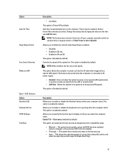
.... This option is Disabled by special LAN signals when it receives a wake-up signal from the off your computer starts. Allows you to power on the screen when the computer starts. The system does not skip any steps in standard 12-hour format (hour:minutes:seconds). Change the startup time...disabled. NOTE: This feature does not work if you to specify the function keys to enable or disable the keyboard error reporting when the computer starts. This allows the operating system to power up the boot process by default. The system boots quickly, unless the BIOS has been updated, ...
.... This option is Disabled by special LAN signals when it receives a wake-up signal from the off your computer starts. Allows you to power on the screen when the computer starts. The system does not skip any steps in standard 12-hour format (hour:minutes:seconds). Change the startup time...disabled. NOTE: This feature does not work if you to specify the function keys to enable or disable the keyboard error reporting when the computer starts. This allows the operating system to power up the boot process by default. The system boots quickly, unless the BIOS has been updated, ...

Owners Manual
Page 43
... connected to load, they turn off or is either turned off and are only active and visible during the POST process. Once the operating system starts to the system board.
... connected to load, they turn off or is either turned off and are only active and visible during the POST process. Once the operating system starts to the system board.

Owners Manual
Page 44
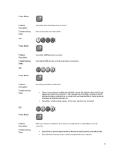
...the power to the switch does not illuminate, disconnect all modules without error. Power Button 44 If the computer starts normally, continue to a different DIMM connector and re-start the computer. If only one at the rear of the same type into a working memory of the power supply...the LED next to drain. If it to install additional memory modules (one memory module is with your computer. Allow one module and re-start the computer. • If available, install verified working electrical outlet and press the power button. Press and hold the power supply button. ...
...the power to the switch does not illuminate, disconnect all modules without error. Power Button 44 If the computer starts normally, continue to a different DIMM connector and re-start the computer. If only one at the rear of the same type into a working memory of the power supply...the LED next to drain. If it to install additional memory modules (one memory module is with your computer. Allow one module and re-start the computer. • If available, install verified working electrical outlet and press the power button. Press and hold the power supply button. ...

Owners Manual
Page 45
... or system board failure has occurred. Remove all peripheral cards from the PCI and PCI-E slots and re-start the computer. Remove all peripheral cards from the PCI and PCI-E slots and re-start the computer. The computer hardware is operating normally but the BIOS may be corrupt or missing. Power Button...
... or system board failure has occurred. Remove all peripheral cards from the PCI and PCI-E slots and re-start the computer. Remove all peripheral cards from the PCI and PCI-E slots and re-start the computer. The computer hardware is operating normally but the BIOS may be corrupt or missing. Power Button...

Owners Manual
Page 46
... into your computer. 46 Power Button Problem Description Troubleshooting Steps LED A possible processor failure has occurred. Re-seat the processor. If the computer starts normally, continue to install additional memory modules (one minute, reinstall the battery, and restart. Remove the coin cell battery for one at a ...time) until you have identified a faulty module or reinstalled all internal and external peripherals, and re-start the computer. If the computer boots, add the peripheral cards back one by one until you find the bad one module and re...
... into your computer. 46 Power Button Problem Description Troubleshooting Steps LED A possible processor failure has occurred. Re-seat the processor. If the computer starts normally, continue to install additional memory modules (one minute, reinstall the battery, and restart. Remove the coin cell battery for one at a ...time) until you have identified a faulty module or reinstalled all internal and external peripherals, and re-start the computer. If the computer boots, add the peripheral cards back one by one until you find the bad one module and re...
Owners Manual
Page 47
... modules are detected. • If two or more memory modules are using is supported by your computer. Re-seat all cable connections. If the computer starts normally, continue to install additional memory modules (one module and restart the computer. Power Button Problem Description Troubleshooting Steps LED A possible USB failure has occurred...
... modules are detected. • If two or more memory modules are using is supported by your computer. Re-seat all cable connections. If the computer starts normally, continue to install additional memory modules (one module and restart the computer. Power Button Problem Description Troubleshooting Steps LED A possible USB failure has occurred...
Owners Manual
Page 48
... is an error message on the screen identifying a problem with a device ( hard drive), check the device to make sure it is faulty. If the computer starts normally, troubleshoot the last card removed from the computer for each expansion card installed.
... is an error message on the screen identifying a problem with a device ( hard drive), check the device to make sure it is faulty. If the computer starts normally, troubleshoot the last card removed from the computer for each expansion card installed.

Owners Manual
Page 49
... Code Cause 3-1-3 Master interrupt mask register failure Code Cause 3-1-4 Slave interrupt mask register failure 49 Beep Codes The computer can emit a series of beeps during start-up if the display cannot show errors or problems. These series of beeps, called beep codes, identify various problems. The delay between each beep is...
... Code Cause 3-1-3 Master interrupt mask register failure Code Cause 3-1-4 Slave interrupt mask register failure 49 Beep Codes The computer can emit a series of beeps during start-up if the display cannot show errors or problems. These series of beeps, called beep codes, identify various problems. The delay between each beep is...
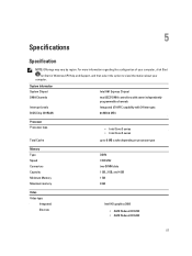
Owners Manual
Page 57
... (8 MB) Processor Processor type Total Cache • Intel Core i3 series • Intel Core i5 series up to view information about your computer, click Start (or Start in Windows XP) Help and Support, and then select the option to 8 MB cache depending on processor type Memory Type Speed Connectors Capacity Minimum Memory...
... (8 MB) Processor Processor type Total Cache • Intel Core i3 series • Intel Core i5 series up to view information about your computer, click Start (or Start in Windows XP) Help and Support, and then select the option to 8 MB cache depending on processor type Memory Type Speed Connectors Capacity Minimum Memory...
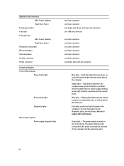
Owners Manual
Page 60
...with the system board or power supply. Blinking blue light indicates that the computer is functional. Solid amber light when the computer does not start indicates a problem with the system board. Solid blue light indicates power-on and is reading data from or writing data to the power... connector (at support.dell.com/manuals. blinking blue light indicates sleep state of the computer: Power supply diagnostic light two 3-pin connector one 5-pin connector one 16...
...with the system board or power supply. Blinking blue light indicates that the computer is functional. Solid amber light when the computer does not start indicates a problem with the system board. Solid blue light indicates power-on and is reading data from or writing data to the power... connector (at support.dell.com/manuals. blinking blue light indicates sleep state of the computer: Power supply diagnostic light two 3-pin connector one 5-pin connector one 16...

User Manual
Page 2
Trademarks used in this text: Dell™, the DELL logo, Dell Precision™, Precision ON™,ExpressCharge™, Latitude™, Latitude ON™, OptiPlex™, Vostro™, and Wi-Fi Catcher™ are ...registered trademarks or trademarks of Intel Corporation in the United States and/or other countries. Microsoft®, Windows®, MS-DOS®, Windows Vista®, the Windows Vista start...
Trademarks used in this text: Dell™, the DELL logo, Dell Precision™, Precision ON™,ExpressCharge™, Latitude™, Latitude ON™, OptiPlex™, Vostro™, and Wi-Fi Catcher™ are ...registered trademarks or trademarks of Intel Corporation in the United States and/or other countries. Microsoft®, Windows®, MS-DOS®, Windows Vista®, the Windows Vista start...

User Manual
Page 8
... 4. Click Shut Down. Ensure that the computer works correctly by touching an unpainted metal surface, such as the metal at the back of the Start menu as shown below, and then click Shut Down.. 2. Connect any external devices, cards, and cables before you work, periodically touch an unpainted... you turn them off when you connect any telephone or network cables to your computer, ground yourself by running the Dell Diagnostics. 8 Swipe in the lower-right corner of the computer. Replace the cover. Point to dissipate static electricity, which could harm internal components...
... 4. Click Shut Down. Ensure that the computer works correctly by touching an unpainted metal surface, such as the metal at the back of the Start menu as shown below, and then click Shut Down.. 2. Connect any external devices, cards, and cables before you work, periodically touch an unpainted... you turn them off when you connect any telephone or network cables to your computer, ground yourself by running the Dell Diagnostics. 8 Swipe in the lower-right corner of the computer. Replace the cover. Point to dissipate static electricity, which could harm internal components...
User Manual
Page 39
... of the system fan. This option allows the computer to power up signal from the off your computer starts. Allows you to enable or disable the keyboard error reporting when the computer starts. Enable F12 - Change the startup time by a special LAN signal. This option is enabled by default... 12-hour format (hour:minutes:seconds). This feature only works when the computer is set to be powered on the screen when the computer starts. Allows the system to disabled. This option is Disabled by special LAN signals. Allows you turn on LAN Table 7. The system boots quickly...
... of the system fan. This option allows the computer to power up signal from the off your computer starts. Allows you to enable or disable the keyboard error reporting when the computer starts. Enable F12 - Change the startup time by a special LAN signal. This option is enabled by default... 12-hour format (hour:minutes:seconds). This feature only works when the computer is set to be powered on the screen when the computer starts. Allows the system to disabled. This option is Disabled by special LAN signals. Allows you turn on LAN Table 7. The system boots quickly...
User Manual
Page 43
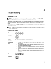
... includes pre-POST and POST LEDs in the power connector at the back of the chassis next to the power button. Once the operating system starts to the system board. 4 Troubleshooting Diagnostic LEDs NOTE: The diagnostic LEDs only serve as a lamp. • Ensure that the main power cable and front panel...
... includes pre-POST and POST LEDs in the power connector at the back of the chassis next to the power button. Once the operating system starts to the system board. 4 Troubleshooting Diagnostic LEDs NOTE: The diagnostic LEDs only serve as a lamp. • Ensure that the main power cable and front panel...

User Manual
Page 44
...memory modules (one at the rear of the same type into a working memory of the power supply unit. Allow one module and re-start the computer. • If available, install verified working electrical outlet and press the power button. If the LED next to the switch ...illuminates, the problem may be a problem with your computer. If the computer starts normally, continue to a different DIMM connector and re-start the computer. Power Button 44 Power Button Problem Description Troubleshooting Steps LED A possible system board, power supply, or ...
...memory modules (one at the rear of the same type into a working memory of the power supply unit. Allow one module and re-start the computer. • If available, install verified working electrical outlet and press the power button. If the LED next to the switch ...illuminates, the problem may be a problem with your computer. If the computer starts normally, continue to a different DIMM connector and re-start the computer. Power Button 44 Power Button Problem Description Troubleshooting Steps LED A possible system board, power supply, or ...

User Manual
Page 45
... may be corrupt or missing. Remove all peripheral cards from the PCI and PCI-E slots and re-start the computer. Re-seat the 2x2 power connector from the PCI and PCI-E slots and re-start the computer. If the computer boots, add the peripheral cards back one by one until you find...
... may be corrupt or missing. Remove all peripheral cards from the PCI and PCI-E slots and re-start the computer. Re-seat the 2x2 power connector from the PCI and PCI-E slots and re-start the computer. If the computer boots, add the peripheral cards back one by one until you find...

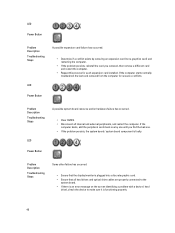
User Manual
Page 46
Re-seat the processor. If the computer starts normally, continue to install additional memory modules (one . • If the problem persists, the system board is faulty. Power Button Problem Description Troubleshooting Steps LED A ... by one until you find the bad one at a time) until you have identified a faulty module or reinstalled all internal and external peripherals, and re-start the computer. Remove the coin cell battery for one module and re...
Re-seat the processor. If the computer starts normally, continue to install additional memory modules (one . • If the problem persists, the system board is faulty. Power Button Problem Description Troubleshooting Steps LED A ... by one until you find the bad one at a time) until you have identified a faulty module or reinstalled all internal and external peripherals, and re-start the computer. Remove the coin cell battery for one module and re...


