
Statement of Volatility
Page 1
... Telephone: 512.338.4400 Telefax: 512.728.3653 Date: June 04, 2012 Subject: Statement of system memory. Dell OptiPlex 3010 To whom it may concern: The Dell OptiPlex 3010 contains both "volatile" and "non-volatile" (NV) components. Non-Volatile EEPROM No memory. 2Kbit (256 bytes) One Device present on DIMM modules and will depend on each DIMM. System...
... Telephone: 512.338.4400 Telefax: 512.728.3653 Date: June 04, 2012 Subject: Statement of system memory. Dell OptiPlex 3010 To whom it may concern: The Dell OptiPlex 3010 contains both "volatile" and "non-volatile" (NV) components. Non-Volatile EEPROM No memory. 2Kbit (256 bytes) One Device present on DIMM modules and will depend on each DIMM. System...
Statement of Volatility
Page 2
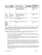
... this state, the dynamic RAM is called "suspend to RAM" state or stand-by the processor. Windows 7, support S4 state. cache or memory. type - Dell systems will lose data once power is the shut off state, coming back to the working state where the dynamic RAM is maintained and is... CDROM/RW/ DVD/ DVD+RW/ Diskette Drives User replaceable Non Volatile optical/magnetic Yes media Low level format / erase All other components on the memory (DDR3, 1600/ 1333MHz). If the system has been commanded to enter S4, the OS will require a complete boot when awakened. The system will...
... this state, the dynamic RAM is called "suspend to RAM" state or stand-by the processor. Windows 7, support S4 state. cache or memory. type - Dell systems will lose data once power is the shut off state, coming back to the working state where the dynamic RAM is maintained and is... CDROM/RW/ DVD/ DVD+RW/ Diskette Drives User replaceable Non Volatile optical/magnetic Yes media Low level format / erase All other components on the memory (DDR3, 1600/ 1333MHz). If the system has been commanded to enter S4, the OS will require a complete boot when awakened. The system will...
Guidebook
Page 2
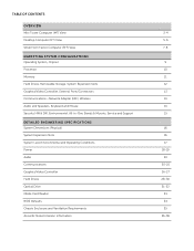
... OF CONTENTS OVERVIEW Mini Tower Computer (MT) View Desktop Computer (DT) View Small Form Factor Computer (SFF) View MARKETING SYSTEM CONFIGURATIONS Operating System, Chipset Processor Memory Hard Drives, Removable Storage, System Expansion Slots Graphics/Video Controller, External Ports/Connectors Communications-Network Adapter (NIC), Wireless Audio and Speakers, Keyboard and Mouse Security...
... OF CONTENTS OVERVIEW Mini Tower Computer (MT) View Desktop Computer (DT) View Small Form Factor Computer (SFF) View MARKETING SYSTEM CONFIGURATIONS Operating System, Chipset Processor Memory Hard Drives, Removable Storage, System Expansion Slots Graphics/Video Controller, External Ports/Connectors Communications-Network Adapter (NIC), Wireless Audio and Speakers, Keyboard and Mouse Security...
Guidebook
Page 4
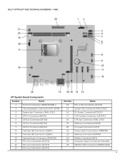
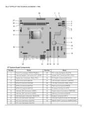
DELL™ OPTIPLEX™ 3010 TECHNICAL GUIDEBOOK -FINAL MT System Board Components Number 1 2 3 4 5 6 7 8 9 10 11 12 13 Name Front IO connector (FRONTPANEL)) Internal Speaker Connector (INT_SPKR) System fan Connector (FAN_SYS1) ... 22 23 24 25 Name PCI-e 16x Connector (SLOT1) System fan Connector (FAN_SYS2) P2 Power Connector(ATX12V) CPU Socket Connector (U27CPU) CPU fan Connector (FAN_CPU) Memory Connector(DIMM1) P1 power Connector (ATX) Power Switch Connector (PWRSW1) Memory Connector(DIMM2) Battery Connector (BT1) Intrusion Switch Connector (Intruder) KB/MS COM Connector (KBMSCOM1) 4
DELL™ OPTIPLEX™ 3010 TECHNICAL GUIDEBOOK -FINAL MT System Board Components Number 1 2 3 4 5 6 7 8 9 10 11 12 13 Name Front IO connector (FRONTPANEL)) Internal Speaker Connector (INT_SPKR) System fan Connector (FAN_SYS1) ... 22 23 24 25 Name PCI-e 16x Connector (SLOT1) System fan Connector (FAN_SYS2) P2 Power Connector(ATX12V) CPU Socket Connector (U27CPU) CPU fan Connector (FAN_CPU) Memory Connector(DIMM1) P1 power Connector (ATX) Power Switch Connector (PWRSW1) Memory Connector(DIMM2) Battery Connector (BT1) Intrusion Switch Connector (Intruder) KB/MS COM Connector (KBMSCOM1) 4
Guidebook
Page 6
DELL™ OPTIPLEX™ 3010 TECHNICAL GUIDEBOOK -FINAL DT System Board Components Number Name 1 Front IO connector (FRONTPANEL)) 2 Internal Speaker Connector (INT_SPKR) 3 System fan Connector (FAN_SYS1) 4 SATA 1 Connector(SATA1) ...25 Name PCI-e 16x Connector (SLOT1) System fan Connector (FAN_SYS2) P2 Power Connector(ATX12V) CPU Socket Connector (U27CPU) CPU fan Connector (FAN_CPU) Memory Connector(DIMM1) P1 power Connector (ATX) Power Switch Connector (PWRSW1) Memory Connector(DIMM2) Battery Connector (BT1) Intrusion Switch Connector (Intruder) KB/MS COM Connector (KBMSCOM1) 6
DELL™ OPTIPLEX™ 3010 TECHNICAL GUIDEBOOK -FINAL DT System Board Components Number Name 1 Front IO connector (FRONTPANEL)) 2 Internal Speaker Connector (INT_SPKR) 3 System fan Connector (FAN_SYS1) 4 SATA 1 Connector(SATA1) ...25 Name PCI-e 16x Connector (SLOT1) System fan Connector (FAN_SYS2) P2 Power Connector(ATX12V) CPU Socket Connector (U27CPU) CPU fan Connector (FAN_CPU) Memory Connector(DIMM1) P1 power Connector (ATX) Power Switch Connector (PWRSW1) Memory Connector(DIMM2) Battery Connector (BT1) Intrusion Switch Connector (Intruder) KB/MS COM Connector (KBMSCOM1) 6
Guidebook
Page 9
...e c o n fi g u r a t i o n o f y o u r c o m p u t e r , c l i c k Start>Help and Support and select the option to view information about your computer. no dedicated LOM EEPROM 9 DELL™ OPTIPLEX™ 3010 TECHNICAL GUIDEBOOK -FINAL MARKETING SYSTEM CONFIGURATIONS N O T E : O ff e r i n g s m a y v a r y b y c o u n t r y . OPERATING SYSTEM Windows 7® operating system Other OS Media Support MT DT SFF Microsoft®...bit), Ubuntu® Linux (32bit) Optional CHIPSET Chipset Non-volatile memory on chipset BIOS Configuration SPI (Serial Peripheral Interface) NIC EEPROM MT...
...e c o n fi g u r a t i o n o f y o u r c o m p u t e r , c l i c k Start>Help and Support and select the option to view information about your computer. no dedicated LOM EEPROM 9 DELL™ OPTIPLEX™ 3010 TECHNICAL GUIDEBOOK -FINAL MARKETING SYSTEM CONFIGURATIONS N O T E : O ff e r i n g s m a y v a r y b y c o u n t r y . OPERATING SYSTEM Windows 7® operating system Other OS Media Support MT DT SFF Microsoft®...bit), Ubuntu® Linux (32bit) Optional CHIPSET Chipset Non-volatile memory on chipset BIOS Configuration SPI (Serial Peripheral Interface) NIC EEPROM MT...
Guidebook
Page 11
... systems. Type: DDR3 Synch DRAM Non-ECC Memory DIMM Slots DIMM Capacities Minimum Memory Maximum System Memory MT 2 Up to 4GB 1GB 8GB1 DT 1333 & 1600MHz 2 2 Up to 4GB 1GB 8GB1 SFF 2 Up to operate, but with a slight reduction in performance. DELL™ OPTIPLEX™ 3010 TECHNICAL GUIDEBOOK -FINAL MEMORY NOTE: Memory modules should be less than 4GB.
... systems. Type: DDR3 Synch DRAM Non-ECC Memory DIMM Slots DIMM Capacities Minimum Memory Maximum System Memory MT 2 Up to 4GB 1GB 8GB1 DT 1333 & 1600MHz 2 2 Up to 4GB 1GB 8GB1 SFF 2 Up to operate, but with a slight reduction in performance. DELL™ OPTIPLEX™ 3010 TECHNICAL GUIDEBOOK -FINAL MEMORY NOTE: Memory modules should be less than 4GB.
Guidebook
Page 20
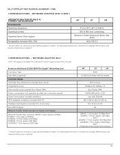
DELL™ OPTIPLEX™ 3010 TECHNICAL GUIDEBOOK -FINAL AUDIO INTEGRATED CONEXANT CX20641 HIGH DEFINITION AUDIO High Definition Stereo support Number of channels Number of Bits / Audio resolution Sampling rate (...peak) / 1Watt (average) INTEGRATED REALTEK® RTL8111E-VL ETHERNET LAN 10/100/1000 External Connector Type Data Rates supported Controller Details Controller bus architecture Integrated memory Data transfer mode (example Bus-Master DMA) Power consumption (full operation per data rate connection speed) Power consumption (standby operation) IEEE standards compliance (example ...
DELL™ OPTIPLEX™ 3010 TECHNICAL GUIDEBOOK -FINAL AUDIO INTEGRATED CONEXANT CX20641 HIGH DEFINITION AUDIO High Definition Stereo support Number of channels Number of Bits / Audio resolution Sampling rate (...peak) / 1Watt (average) INTEGRATED REALTEK® RTL8111E-VL ETHERNET LAN 10/100/1000 External Connector Type Data Rates supported Controller Details Controller bus architecture Integrated memory Data transfer mode (example Bus-Master DMA) Power consumption (full operation per data rate connection speed) Power consumption (standby operation) IEEE standards compliance (example ...
Guidebook
Page 21
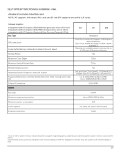
... ADAPTER (NIC) NOTE: MT supports full height (FH) cards and DT and SFF supports low profile (LP) cards. DELL™ OPTIPLEX™ 3010 TECHNICAL GUIDEBOOK -FINAL COMMUNICATIONS - For high speed transmission, connection to 80% (non-condensing) Operating System Driver Support Windows 7.../100/1000 PCIe Gigabit1 Networking Card Connector Type Data Rates supported Controller Details Controller bus architecture (example PCIe 1.0a x1) Integrated memory Data transfer mode (example Bus-Master DMA) Power consumption (full operation per data rate connection speed) Power consumption (standby operation)...
... ADAPTER (NIC) NOTE: MT supports full height (FH) cards and DT and SFF supports low profile (LP) cards. DELL™ OPTIPLEX™ 3010 TECHNICAL GUIDEBOOK -FINAL COMMUNICATIONS - For high speed transmission, connection to 80% (non-condensing) Operating System Driver Support Windows 7.../100/1000 PCIe Gigabit1 Networking Card Connector Type Data Rates supported Controller Details Controller bus architecture (example PCIe 1.0a x1) Integrated memory Data transfer mode (example Bus-Master DMA) Power consumption (full operation per data rate connection speed) Power consumption (standby operation)...
Guidebook
Page 26
...Dual Core and Celeron® CPUs) Bus Type GPU core clock Frame Buffer Memory (onboard and shared) Size and Speed Overlay Planes Maximum Color Depth Maximum Vertical ... native HDMI Output) HDMI 1 Up to 1.7 GB of system memory may be allocated to support integrated graphics, depending on operating system, system memory size and other factors. 2 DVI and VGA can be used concurrently for multi-monitor display in DOS 26 DELL™ OPTIPLEX™ 3010 TECHNICAL GUIDEBOOK -FINAL GRAPHICS/VIDEO CONTROLLER N O T E : M T s u p p o r t s f u l l h e i g h t ( F H ) c a r d s a n d D T a n d S F F s u p...
...Dual Core and Celeron® CPUs) Bus Type GPU core clock Frame Buffer Memory (onboard and shared) Size and Speed Overlay Planes Maximum Color Depth Maximum Vertical ... native HDMI Output) HDMI 1 Up to 1.7 GB of system memory may be allocated to support integrated graphics, depending on operating system, system memory size and other factors. 2 DVI and VGA can be used concurrently for multi-monitor display in DOS 26 DELL™ OPTIPLEX™ 3010 TECHNICAL GUIDEBOOK -FINAL GRAPHICS/VIDEO CONTROLLER N O T E : M T s u p p o r t s f u l l h e i g h t ( F H ) c a r d s a n d D T a n d S F F s u p...

Guidebook
Page 27
...RH 0-20,000 ft. 1GB AMD RADEON™ HD7470 Bus Type (example integrated or PCIe x16) GPU core clock Frame Buffer Memory (onboard and shared) Size and Speed Maximum power consumption Overlay Planes Maximum Color Depth Maximum Vertical Refresh Rate Multiple Display Support Supported Resolutions... 75Hz DispalyPort Max: 2560 x 1600/32bpp @ 75Hz Min : 640x480/8bpp @ 60Hz 1 DVI-I and 1 DP Yes (For native DP). DELL™ OPTIPLEX™ 3010 TECHNICAL GUIDEBOOK -FINAL GRAPHICS/VIDEO CONTROLLER (CONT.) 1GB AMD RADEON™ HD7570 Bus Type (example integrated or PCIe x16) GPU core clock Frame ...
...RH 0-20,000 ft. 1GB AMD RADEON™ HD7470 Bus Type (example integrated or PCIe x16) GPU core clock Frame Buffer Memory (onboard and shared) Size and Speed Maximum power consumption Overlay Planes Maximum Color Depth Maximum Vertical Refresh Rate Multiple Display Support Supported Resolutions... 75Hz DispalyPort Max: 2560 x 1600/32bpp @ 75Hz Min : 640x480/8bpp @ 60Hz 1 DVI-I and 1 DP Yes (For native DP). DELL™ OPTIPLEX™ 3010 TECHNICAL GUIDEBOOK -FINAL GRAPHICS/VIDEO CONTROLLER (CONT.) 1GB AMD RADEON™ HD7570 Bus Type (example integrated or PCIe x16) GPU core clock Frame ...
Guidebook
Page 33
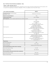
MCR is supported via a F5 to 95% RH 33 DELL™ OPTIPLEX™ 3010 TECHNICAL GUIDEBOOK -FINAL MEDIA CARD READER (MCR) NOTE: Dell 19 in 1 Media Card Reader (MCR) is not available on selectable configuration. W x H) 3.99/(10.13cm)/1.0/(2.54cm) Weight (max) pounds/kilograms ~155g Interface type ...) RS Multi Media Card plus (RS-MMC plus) Multi Media Card Micro(MMC Micro) (with adapter) Memory Stick (MS) Memory Stick Pro(MS Pro) Memory Stick Pro Duo (MS Pro Duo) Memory Stick Duo (MS-Duo) Memory Stick Micro(MS Micro)(M2) (with adapter) Smart Media (SM) xD Compact Flash type I/II Version ...
MCR is supported via a F5 to 95% RH 33 DELL™ OPTIPLEX™ 3010 TECHNICAL GUIDEBOOK -FINAL MEDIA CARD READER (MCR) NOTE: Dell 19 in 1 Media Card Reader (MCR) is not available on selectable configuration. W x H) 3.99/(10.13cm)/1.0/(2.54cm) Weight (max) pounds/kilograms ~155g Interface type ...) RS Multi Media Card plus (RS-MMC plus) Multi Media Card Micro(MMC Micro) (with adapter) Memory Stick (MS) Memory Stick Pro(MS Pro) Memory Stick Pro Duo (MS Pro Duo) Memory Stick Duo (MS-Duo) Memory Stick Micro(MS Micro)(M2) (with adapter) Smart Media (SM) xD Compact Flash type I/II Version ...
Guidebook
Page 36
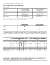
...7.6.2, and C.15.2 and declared in ISO 7779, but was measured using the same microphone distances and measurement techniques defined for the Dell OptiPlex 3010 MT is as follows: (all values LWAd expressed in bels; 1 bel=10 decibels, re 10-12 Watts) Operating Mode Idle...other reported operating modes. 2 Declared Sound Power rounded to ISO 9296 except 90% CPU. DELL™ OPTIPLEX™ 3010 TECHNICAL GUIDEBOOK -FINAL ACOUSTIC NOISE EMISSION INFORMATION OPTIPLEX 3010 MT Component CPU Memory HDD (#, capacity) RMSD Graphics Adapter Typical Configuration Intel i5,3.1GHZ,4c SNB 95W 4GB DDR3...
...7.6.2, and C.15.2 and declared in ISO 7779, but was measured using the same microphone distances and measurement techniques defined for the Dell OptiPlex 3010 MT is as follows: (all values LWAd expressed in bels; 1 bel=10 decibels, re 10-12 Watts) Operating Mode Idle...other reported operating modes. 2 Declared Sound Power rounded to ISO 9296 except 90% CPU. DELL™ OPTIPLEX™ 3010 TECHNICAL GUIDEBOOK -FINAL ACOUSTIC NOISE EMISSION INFORMATION OPTIPLEX 3010 MT Component CPU Memory HDD (#, capacity) RMSD Graphics Adapter Typical Configuration Intel i5,3.1GHZ,4c SNB 95W 4GB DDR3...
Guidebook
Page 37
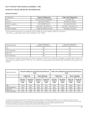
... reported operating modes. 2 Declared Sound Power rounded to ISO 9296 except 90% CPU. DELL™ OPTIPLEX™ 3010 TECHNICAL GUIDEBOOK -FINAL ACOUSTIC NOISE EMISSION INFORMATION OPTIPLEX 3010 DT Component CPU Memory HDD (#, capacity) RMSD Graphics Adapter Typical Configuration Intel i5,3.1GHZ,4c SNB 95W 4GB ...9296 for this mode, the system CPU was measured using the same microphone distances and measurement techniques defined for the Dell OptiPlex 3010 DT is as follows1: Operating Mode Idle HDD Operating 90% CPU ODD Operating Typical Configuration Declared Sound Pressure High-...
... reported operating modes. 2 Declared Sound Power rounded to ISO 9296 except 90% CPU. DELL™ OPTIPLEX™ 3010 TECHNICAL GUIDEBOOK -FINAL ACOUSTIC NOISE EMISSION INFORMATION OPTIPLEX 3010 DT Component CPU Memory HDD (#, capacity) RMSD Graphics Adapter Typical Configuration Intel i5,3.1GHZ,4c SNB 95W 4GB ...9296 for this mode, the system CPU was measured using the same microphone distances and measurement techniques defined for the Dell OptiPlex 3010 DT is as follows1: Operating Mode Idle HDD Operating 90% CPU ODD Operating Typical Configuration Declared Sound Pressure High-...

Guidebook
Page 38
... operating modes. 2 Declared Sound Power rounded to ISO 9296 except 90% CPU. DELL™ OPTIPLEX™ 3010 TECHNICAL GUIDEBOOK -FINAL ACOUSTIC NOISE EMISSION INFORMATION OPTIPLEX 3010 SFF Component CPU Typical Configuration Intel i5,3.1GHZ,4c SNB 95W High-end Configuration Intel 95W TDP Memory 4GB DDR3 1333MHz 4GB DDR3 1333MHz HDD (#, capacity) 1TB 7200RPM SATA3 1TB...
... operating modes. 2 Declared Sound Power rounded to ISO 9296 except 90% CPU. DELL™ OPTIPLEX™ 3010 TECHNICAL GUIDEBOOK -FINAL ACOUSTIC NOISE EMISSION INFORMATION OPTIPLEX 3010 SFF Component CPU Typical Configuration Intel i5,3.1GHZ,4c SNB 95W High-end Configuration Intel 95W TDP Memory 4GB DDR3 1333MHz 4GB DDR3 1333MHz HDD (#, capacity) 1TB 7200RPM SATA3 1TB...

Owners Manual
Page 3
... Card...12 Removing the Optical Drive...12 Installing The Optical Drive...13 Removing the Hard Drive...13 Installing The Hard Drive...15 Removing the Memory...15 Installing The Memory...16 Removing the Chassis Intrusion Switch...16 Installing The Chassis Intrusion Switch...17 Removing The Speaker...17 Installing The Speaker...18 Removing The...
... Card...12 Removing the Optical Drive...12 Installing The Optical Drive...13 Removing the Hard Drive...13 Installing The Hard Drive...15 Removing the Memory...15 Installing The Memory...16 Removing the Chassis Intrusion Switch...16 Installing The Chassis Intrusion Switch...17 Removing The Speaker...17 Installing The Speaker...18 Removing The...

Owners Manual
Page 4
... file name ...51 Bad error-correction code (ECC) on disk read 51 Controller has failed...52 Data error ...52 Decreasing available memory ...52 Diskette drive 0 seek failure...52 Diskette read failure...52 Diskette subsystem reset failed...52 Gate A20 failure...52 General failure ..., please populate DIMM1 53 Keyboard failure...53 Memory address line failure at address, read value expecting value 53 Memory allocation error...53 Memory data line failure at checkpoint [nnnn]. Previous attempts at booting this checkpoint and contact Dell Technical Support 51 Alert! For help in resolving this...
... file name ...51 Bad error-correction code (ECC) on disk read 51 Controller has failed...52 Data error ...52 Decreasing available memory ...52 Diskette drive 0 seek failure...52 Diskette read failure...52 Diskette subsystem reset failed...52 Gate A20 failure...52 General failure ..., please populate DIMM1 53 Keyboard failure...53 Memory address line failure at address, read value expecting value 53 Memory allocation error...53 Memory data line failure at checkpoint [nnnn]. Previous attempts at booting this checkpoint and contact Dell Technical Support 51 Alert! For help in resolving this...

Owners Manual
Page 5
... logic failure at address, read value expecting value 54 Memory odd/even logic failure at address, read value expecting value 54 Memory write/read failure at address, read value expecting value 54 Memory size in CMOS invalid...54 Memory tests terminated by calling your hard drive by keystroke...54 ... not set-please run the System Setup program 55 Timer chip counter 2 failed ...56 Unexpected interrupt in protected mode...56 WARNING: Dell's Disk Monitoring System has detected that drive [0/1] on selected drive...56 X:\ is not ready 56 5 Specifications...57 Specification...57 6 Contacting...
... logic failure at address, read value expecting value 54 Memory odd/even logic failure at address, read value expecting value 54 Memory write/read failure at address, read value expecting value 54 Memory size in CMOS invalid...54 Memory tests terminated by calling your hard drive by keystroke...54 ... not set-please run the System Setup program 55 Timer chip counter 2 failed ...56 Unexpected interrupt in protected mode...56 WARNING: Dell's Disk Monitoring System has detected that drive [0/1] on selected drive...56 X:\ is not ready 56 5 Specifications...57 Specification...57 6 Contacting...

Owners Manual
Page 15
... Drive Installing The Hard Drive 1. Tighten the screws to secure the 2.5 inch hard drive(s) to the back of the hard drive(s). 5. Release the memory-retention clips on each side of the hard drive bracket. Press the hard-drive bracket latch towards the hard drive and insert it into the... bracket. 3. Related Links Removing The Hard Drive Removing the Memory 1. Release the screws that secure the 2.5 inch hard drive to the underside of the memory modules. 15 Remove the cover. 3. Flex the hard-drive bracket and then insert the single 3.5 inch ...
... Drive Installing The Hard Drive 1. Tighten the screws to secure the 2.5 inch hard drive(s) to the back of the hard drive(s). 5. Release the memory-retention clips on each side of the hard drive bracket. Press the hard-drive bracket latch towards the hard drive and insert it into the... bracket. 3. Related Links Removing The Hard Drive Removing the Memory 1. Release the screws that secure the 2.5 inch hard drive to the underside of the memory modules. 15 Remove the cover. 3. Flex the hard-drive bracket and then insert the single 3.5 inch ...

Owners Manual
Page 16
...back to secure them in the order of the connectors on the system board. Related Links Removing The Memory Removing the Chassis Intrusion Switch 1. Install the memory module in place. 3. Follow the procedures in Before Working Inside Your Computer. 2. Disconnect the intrusion-switch... cable from the system board. 16 Install the cover. 4. Insert the memory modules into the connectors on the system board. Remove the cover. 3. Follow the procedures in After Working Inside Your Computer. Related Links...
...back to secure them in the order of the connectors on the system board. Related Links Removing The Memory Removing the Chassis Intrusion Switch 1. Install the memory module in place. 3. Follow the procedures in Before Working Inside Your Computer. 2. Disconnect the intrusion-switch... cable from the system board. 16 Install the cover. 4. Insert the memory modules into the connectors on the system board. Remove the cover. 3. Follow the procedures in After Working Inside Your Computer. Related Links...


