User Manual
Page 1
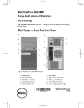
Mini-Tower - optical-drive eject button 8. power-supply diagnostic light Regulatory Model: D04S, D07D, D12M Regulatory Type: D04S001, D07D001, D12M001 2012 - 05 optical drive bay 3. headphone connector 4. power button 2. USB 2.0 connectors (2) 9. Front And Back View Figure 1. hard-drive activity light 10. diagnostic lights (4) 6. microphone connector 5. Front And Back View Of Mini-Tower 1. optical drive 7. Dell OptiPlex 390/3010 Setup And Features Information About Warnings WARNING: A WARNING indicates a potential for property damage, personal injury, or death.
Mini-Tower - optical-drive eject button 8. power-supply diagnostic light Regulatory Model: D04S, D07D, D12M Regulatory Type: D04S001, D07D001, D12M001 2012 - 05 optical drive bay 3. headphone connector 4. power button 2. USB 2.0 connectors (2) 9. Front And Back View Figure 1. hard-drive activity light 10. diagnostic lights (4) 6. microphone connector 5. Front And Back View Of Mini-Tower 1. optical drive 7. Dell OptiPlex 390/3010 Setup And Features Information About Warnings WARNING: A WARNING indicates a potential for property damage, personal injury, or death.
User Manual
Page 2
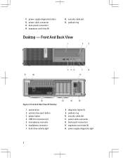
... 14. security cable slot 16. power button 4. hard-drive activity light 8. power cable connector 12. optical drive 2. security cable slot 11. back panel connectors 13. power-supply diagnostic light 2 headphone connector 7. Front And Back View Of Desktop 1. padlock... ring Desktop - expansion card slots (4) 14. power cable connector 13. expansion card slots (4) 15. microphone connector 6. diagnostic lights (4) 9. 11. power-supply diagnostic button 12. Front ...
... 14. security cable slot 16. power button 4. hard-drive activity light 8. power cable connector 12. optical drive 2. security cable slot 11. back panel connectors 13. power-supply diagnostic light 2 headphone connector 7. Front And Back View Of Desktop 1. padlock... ring Desktop - expansion card slots (4) 14. power cable connector 13. expansion card slots (4) 15. microphone connector 6. diagnostic lights (4) 9. 11. power-supply diagnostic button 12. Front ...
User Manual
Page 3
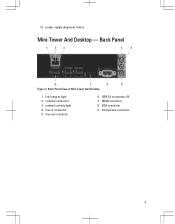
link integrity light 2. VGA connector 9. network connector 3. line-out connector 6. microphone connector 3 power-supply diagnostic button Mini-Tower And Desktop - HDMI connector 8. Back Panel View of Mini-Tower And Desktop 1. network activity light 4. line-in connector 5. USB 2.0 connectors (6) 7. 15. Back Panel Figure 3.
link integrity light 2. VGA connector 9. network connector 3. line-out connector 6. microphone connector 3 power-supply diagnostic button Mini-Tower And Desktop - HDMI connector 8. Back Panel View of Mini-Tower And Desktop 1. network activity light 4. line-in connector 5. USB 2.0 connectors (6) 7. 15. Back Panel Figure 3.

User Manual
Page 4
Front And Back View Figure 4. Front And Back View Of Small Form Factor 1. power button 4. hard-drive activity light 9. security cable slot 11. Small Form Factor - optical-drive eject button 3. power cable connector 12. expansion card slots (2) 4 optical drive 2. headphone connector 7. padlock ring 10. power-supply diagnostic light 14. microphone connector 6. back panel connectors 15. USB 2.0 connectors (2) 5. diagnostic lights (4) 8. power-supply diagnostic button 13.
Front And Back View Figure 4. Front And Back View Of Small Form Factor 1. power button 4. hard-drive activity light 9. security cable slot 11. Small Form Factor - optical-drive eject button 3. power cable connector 12. expansion card slots (2) 4 optical drive 2. headphone connector 7. padlock ring 10. power-supply diagnostic light 14. microphone connector 6. back panel connectors 15. USB 2.0 connectors (2) 5. diagnostic lights (4) 8. power-supply diagnostic button 13.
Guidebook
Page 3
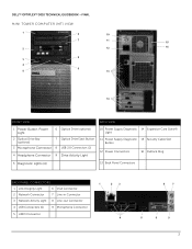
DELL™ OPTIPLEX™ 3010 TECHNICAL GUIDEBOOK -FINAL MINI TOWER COMPUTER (MT) VIEW 1 6 10 7 11 15 2 12 16 8 3 4 9 5 13 14 FRONT VIEW BACK VIEW 1 Power Button, Power Light 6 Optical Drive (optional) 2 Optical Drive Bay (optional) 7 Optical Drive Eject Button 3 Microphone Connector 8 USB 2.0 Connectors (2) 4 Headphone Connector 9 Drive Activity Light 10 Power Supply Diagnostic 14 Expansion Card Slots(4) Light 11...
DELL™ OPTIPLEX™ 3010 TECHNICAL GUIDEBOOK -FINAL MINI TOWER COMPUTER (MT) VIEW 1 6 10 7 11 15 2 12 16 8 3 4 9 5 13 14 FRONT VIEW BACK VIEW 1 Power Button, Power Light 6 Optical Drive (optional) 2 Optical Drive Bay (optional) 7 Optical Drive Eject Button 3 Microphone Connector 8 USB 2.0 Connectors (2) 4 Headphone Connector 9 Drive Activity Light 10 Power Supply Diagnostic 14 Expansion Card Slots(4) Light 11...
Guidebook
Page 5
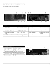
DELL™ OPTIPLEX™ 3010 TECHNICAL GUIDEBOOK -FINAL DESKTOP COMPUTER (DT) VIEW 1 2 3 9 10 11 4 56 7 8 12 13 14 15 FRONT VIEW 1 Optical Drive BACK VIEW 5 Microphone Connector 9 Padlock Ring 13 Expansion Card Slots(4) 2 Optical Drive Eject Button 6 Headphone Connector 10 Security Cable Slot 3 Power Button, Power Light 4 USB Connectors (2) 7 Drive Activity Light 8 Diagnostic Lights (4) 11 Power Connectors 12...
DELL™ OPTIPLEX™ 3010 TECHNICAL GUIDEBOOK -FINAL DESKTOP COMPUTER (DT) VIEW 1 2 3 9 10 11 4 56 7 8 12 13 14 15 FRONT VIEW 1 Optical Drive BACK VIEW 5 Microphone Connector 9 Padlock Ring 13 Expansion Card Slots(4) 2 Optical Drive Eject Button 6 Headphone Connector 10 Security Cable Slot 3 Power Button, Power Light 4 USB Connectors (2) 7 Drive Activity Light 8 Diagnostic Lights (4) 11 Power Connectors 12...
Guidebook
Page 7
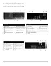
DELL™ OPTIPLEX™ 3010 TECHNICAL GUIDEBOOK -FINAL SMALL FORM FACTOR COMPUTER (SFF) VIEW 1 2 3 9 10 11 12 13 4 56 7 8 14 15 FRONT VIEW 1 Optical Drive 5 Microphone Connector 2 Optical Drive Eject Button 6 Headphone Connector 3 Power Button, Power Light 4 USB 2.0 Connectors (2) 7 Diagnostic Lights (4) 8 Drive Activity Light BACK VIEW 9 Padlock Ring 10 Security Cable Slot 11 Power Connectors 13 Power Supply...
DELL™ OPTIPLEX™ 3010 TECHNICAL GUIDEBOOK -FINAL SMALL FORM FACTOR COMPUTER (SFF) VIEW 1 2 3 9 10 11 12 13 4 56 7 8 14 15 FRONT VIEW 1 Optical Drive 5 Microphone Connector 2 Optical Drive Eject Button 6 Headphone Connector 3 Power Button, Power Light 4 USB 2.0 Connectors (2) 7 Diagnostic Lights (4) 8 Drive Activity Light BACK VIEW 9 Padlock Ring 10 Security Cable Slot 11 Power Connectors 13 Power Supply...

Owners Manual
Page 4
... and Text Error Messages...34 Navigation...34 System Setup Options...35 4 Troubleshooting...43 Diagnostic LEDs...43 Diagnostic Light Patterns...43 Beep Codes...49 Error Messages...51 Address mark not found...51 Alert! Previous attempts at booting this checkpoint and contact Dell Technical Support 51 Alert! For help in resolving this problem, please note this...
... and Text Error Messages...34 Navigation...34 System Setup Options...35 4 Troubleshooting...43 Diagnostic LEDs...43 Diagnostic Light Patterns...43 Beep Codes...49 Error Messages...51 Address mark not found...51 Alert! Previous attempts at booting this checkpoint and contact Dell Technical Support 51 Alert! For help in resolving this problem, please note this...

Owners Manual
Page 43
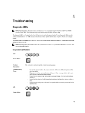
...next to the power button. Power Button 43 These LEDs do not indicate the problem that caused the POST routine to stop. Diagnostic Light Patterns LED Power Button Problem Description Troubleshooting Steps LED The computer is either turned off or is amber or off and are ... the Power-on Self-Test (POST) process. These diagnostic LEDs are only active and visible during the POST process. NOTE: The diagnostic lights will not blink when it with the system easier and more accurate. 4 Troubleshooting Diagnostic LEDs NOTE: The diagnostic LEDs only serve as a lamp. • Ensure ...
...next to the power button. Power Button 43 These LEDs do not indicate the problem that caused the POST routine to stop. Diagnostic Light Patterns LED Power Button Problem Description Troubleshooting Steps LED The computer is either turned off or is amber or off and are ... the Power-on Self-Test (POST) process. These diagnostic LEDs are only active and visible during the POST process. NOTE: The diagnostic lights will not blink when it with the system easier and more accurate. 4 Troubleshooting Diagnostic LEDs NOTE: The diagnostic LEDs only serve as a lamp. • Ensure ...
Owners Manual
Page 60
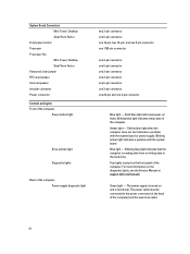
... jumper Internal speaker Intruder connector Power connector Controls and Lights Front of the computer: Power button light Drive activity light Diagnostic lights Back of the computer. Blinking blue light indicates that the computer is functional. Blue light - Green light - Solid amber light when the computer does not start indicates a problem ...connector one 3-pin connector one 5-pin connector one 3-pin connector one 24-pin and one 4-pin connector Blue light - Four lights located on and is reading data from or writing data to the power connector (at support.dell.com/manuals.
... jumper Internal speaker Intruder connector Power connector Controls and Lights Front of the computer: Power button light Drive activity light Diagnostic lights Back of the computer. Blinking blue light indicates that the computer is functional. Blue light - Green light - Solid amber light when the computer does not start indicates a problem ...connector one 3-pin connector one 5-pin connector one 3-pin connector one 24-pin and one 4-pin connector Blue light - Four lights located on and is reading data from or writing data to the power connector (at support.dell.com/manuals.
User Manual
Page 4
... contact Dell Technical Support 51 Alert! Removing the Fan Shelter...31 Installing The Fan Shelter...32 3 System Setup...33 System Setup...33 Boot Menu...33 Boot Menu Enhancements...33 Timing Key Sequences...34 Beep Codes and Text Error Messages...34 Navigation...34 System Setup Options...35 4 Troubleshooting...43 Diagnostic LEDs...43 Diagnostic Light Patterns...
... contact Dell Technical Support 51 Alert! Removing the Fan Shelter...31 Installing The Fan Shelter...32 3 System Setup...33 System Setup...33 Boot Menu...33 Boot Menu Enhancements...33 Timing Key Sequences...34 Beep Codes and Text Error Messages...34 Navigation...34 System Setup Options...35 4 Troubleshooting...43 Diagnostic LEDs...43 Diagnostic Light Patterns...
User Manual
Page 43
... system starts to load, they turn off or is not receiving power. • Re-seat the power cable in an attempt to stop. NOTE: The diagnostic lights will blink when the power button is amber or off, and will not blink when it is working by testing it with the system easier... and more accurate. Diagnostic Light Patterns LED Power Button Problem Description Troubleshooting Steps LED The computer is either turned off and are no other power protection devices to verify that...
... system starts to load, they turn off or is not receiving power. • Re-seat the power cable in an attempt to stop. NOTE: The diagnostic lights will blink when the power button is amber or off, and will not blink when it is working by testing it with the system easier... and more accurate. Diagnostic Light Patterns LED Power Button Problem Description Troubleshooting Steps LED The computer is either turned off and are no other power protection devices to verify that...

User Manual
Page 60
... indicates a problem with the system board. Blinking blue light indicates that the computer is reading data from or writing data to the power connector (at support.dell.com/manuals. For more information on and is turned on the diagnostic lights, see the Service Manual at the back of the computer.... The power supply is functional. Four lights located on state; The power cable must be connected...
... indicates a problem with the system board. Blinking blue light indicates that the computer is reading data from or writing data to the power connector (at support.dell.com/manuals. For more information on and is turned on the diagnostic lights, see the Service Manual at the back of the computer.... The power supply is functional. Four lights located on state; The power cable must be connected...


