Owners Manual
Page 9
... 110 Restoring Your Operating System 110 Using Microsoft Windows System Restore . . . . 111 Using Dell PC Restore by Symantec 111 Using the Operating System Media 114 13 Adding and Replacing Parts 117 Before You Begin 117 Recommended Tools 117 Turning Off Your Computer 117 Before Working Inside Your ...Computer 118 Hard Drive 119 Removing the Hard Drive 120 Replacing the Hard Drive 121 Returning a Hard Drive to Dell 121 Hinge Covers and ...
... 110 Restoring Your Operating System 110 Using Microsoft Windows System Restore . . . . 111 Using Dell PC Restore by Symantec 111 Using the Operating System Media 114 13 Adding and Replacing Parts 117 Before You Begin 117 Recommended Tools 117 Turning Off Your Computer 117 Before Working Inside Your ...Computer 118 Hard Drive 119 Removing the Hard Drive 120 Replacing the Hard Drive 121 Returning a Hard Drive to Dell 121 Hinge Covers and ...
Owners Manual
Page 35
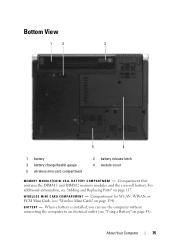
W I R E L E S S M I N I N - About Your Computer 35 For additional information, see "Adding and Replacing Parts" on page 134). Bottom View 1 2 3 5 4 1 battery 3 battery charge/health gauge 5 wireless mini card compartment 2 battery release latch 4 module cover M E M O R Y M O D U L E / C O I C A R D C O M P A R T M E N T - Compartment for WLAN, WWAN, or FCM ...
W I R E L E S S M I N I N - About Your Computer 35 For additional information, see "Adding and Replacing Parts" on page 134). Bottom View 1 2 3 5 4 1 battery 3 battery charge/health gauge 5 wireless mini card compartment 2 battery release latch 4 module cover M E M O R Y M O D U L E / C O I C A R D C O M P A R T M E N T - Compartment for WLAN, WWAN, or FCM ...
Owners Manual
Page 82
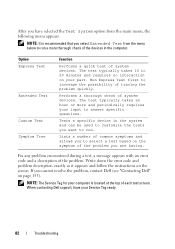
...your computer is recommended that you select Extended Test from the main menu, the following menu appears. If you cannot resolve the problem, contact Dell (see "Contacting Dell" on the symptom of common symptoms and allows you to select a test based on page 155). Performs a thorough check of each test... below to answer specific questions. Write down the error code and problem description exactly as it appears and follow the instructions on your part. The test typically takes 10 to increase the possibility of the devices in the system and can be used to customize the tests ...
...your computer is recommended that you select Extended Test from the main menu, the following menu appears. If you cannot resolve the problem, contact Dell (see "Contacting Dell" on the symptom of common symptoms and allows you to select a test based on page 155). Performs a thorough check of each test... below to answer specific questions. Write down the error code and problem description exactly as it appears and follow the instructions on your part. The test typically takes 10 to increase the possibility of the devices in the system and can be used to customize the tests ...
Owners Manual
Page 106
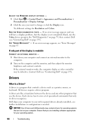
If only part of specialized commands that are installing software appropriate for operating systems that only its driver recognizes. A driver is a program that use the device. NOTICE: Your Drivers and Utilities media may be defective. Contact Dell (see "Error Messages" on page 87...other programs that controls a device such as a printer, mouse, or keyboard. If an error message appears, see "Contacting Dell" on page 155). Dell ships your operating system. 106 Troubleshooting ADJUST THE WINDOWS DISPLAY SETTINGS - 1 Click Start → Control Panel→ Appearance...
If only part of specialized commands that are installing software appropriate for operating systems that only its driver recognizes. A driver is a program that use the device. NOTICE: Your Drivers and Utilities media may be defective. Contact Dell (see "Error Messages" on page 87...other programs that controls a device such as a printer, mouse, or keyboard. If an error message appears, see "Contacting Dell" on page 155). Dell ships your operating system. 106 Troubleshooting ADJUST THE WINDOWS DISPLAY SETTINGS - 1 Click Start → Control Panel→ Appearance...
Owners Manual
Page 117
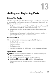
...any open programs. 2 Click Start , click the arrow , and then click Shut Down. The computer turns off your computer. Adding and Replacing Parts 117 Unless otherwise noted, each procedure assumes that the following tools: • Small flat-blade screwdriver • Phillips screwdriver • Small plastic ... website at support.dell.com) Turning Off Your Computer NOTICE: To avoid losing data, save and close any open files and exit any open programs before you turn off after the operating system shutdown process finishes. Adding and Replacing Parts Before You Begin This chapter ...
...any open programs. 2 Click Start , click the arrow , and then click Shut Down. The computer turns off your computer. Adding and Replacing Parts 117 Unless otherwise noted, each procedure assumes that the following tools: • Small flat-blade screwdriver • Phillips screwdriver • Small plastic ... website at support.dell.com) Turning Off Your Computer NOTICE: To avoid losing data, save and close any open files and exit any open programs before you turn off after the operating system shutdown process finishes. Adding and Replacing Parts Before You Begin This chapter ...
Owners Manual
Page 118
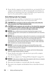
... of cable, press in the Product Information Guide. if you shut down your computer. Hold a card by its edges or by Dell is flat and clean to the computer, perform the following safety guidelines to help protect your computer from potential damage and to help ...prevent damage to prevent the computer cover from their electrical outlets. 118 Adding and Replacing Parts NOTICE: To avoid electrostatic discharge, ground yourself by using a wrist grounding strap or by periodically touching an unpainted metal surface (such as...
... of cable, press in the Product Information Guide. if you shut down your computer. Hold a card by its edges or by Dell is flat and clean to the computer, perform the following safety guidelines to help protect your computer from potential damage and to help ...prevent damage to prevent the computer cover from their electrical outlets. 118 Adding and Replacing Parts NOTICE: To avoid electrostatic discharge, ground yourself by using a wrist grounding strap or by periodically touching an unpainted metal surface (such as...
Owners Manual
Page 119
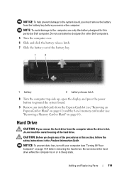
... computer, use batteries designed for this section, follow the safety instructions in the Product Information Guide. Do not use only the battery designed for other Dell computers. 5 Turn the computer over. 6 Slide and click the battery release latch. 7 Slide the battery out of the procedures in Sleep state.... Adding and Replacing Parts 119 Do not remove the hard drive while the computer is on page 117) before you remove the hard drive from the computer when the ...
... computer, use batteries designed for this section, follow the safety instructions in the Product Information Guide. Do not use only the battery designed for other Dell computers. 5 Turn the computer over. 6 Slide and click the battery release latch. 7 Slide the battery out of the procedures in Sleep state.... Adding and Replacing Parts 119 Do not remove the hard drive while the computer is on page 117) before you remove the hard drive from the computer when the ...
Owners Manual
Page 120
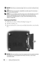
... Discharge" in the Product Information Guide). 120 Adding and Replacing Parts NOTE: If you are extremely fragile. Removing the Hard Drive 1 Follow the procedures in "Before You Begin" on page 107). NOTICE: Hard drives are installing a hard drive from a source other than Dell, you need to install an operating system, drivers, and...
... Discharge" in the Product Information Guide). 120 Adding and Replacing Parts NOTE: If you are extremely fragile. Removing the Hard Drive 1 Follow the procedures in "Before You Begin" on page 107). NOTICE: Hard drives are installing a hard drive from a source other than Dell, you need to install an operating system, drivers, and...
Owners Manual
Page 121
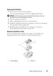
... your computer, as needed (see "Restoring Your Operating System" on page 107). NOTICE: Use firm and even pressure to Dell in transit. 2 1 1 foam packaging 2 hard drive Adding and Replacing Parts 121 Replacing the Hard Drive 1 Remove the new drive from its original, or comparable, foam packaging. Save the original packaging for your...
... your computer, as needed (see "Restoring Your Operating System" on page 107). NOTICE: Use firm and even pressure to Dell in transit. 2 1 1 foam packaging 2 hard drive Adding and Replacing Parts 121 Replacing the Hard Drive 1 Remove the new drive from its original, or comparable, foam packaging. Save the original packaging for your...
Owners Manual
Page 122
... any of the procedures in this section, follow the safety instructions in "Before You Begin" on the back of the computer. 122 Adding and Replacing Parts NOTICE: To avoid electrostatic discharge, ground yourself by using a wrist grounding strap or by periodically touching an unpainted metal surface (such as it will open...
... any of the procedures in this section, follow the safety instructions in "Before You Begin" on the back of the computer. 122 Adding and Replacing Parts NOTICE: To avoid electrostatic discharge, ground yourself by using a wrist grounding strap or by periodically touching an unpainted metal surface (such as it will open...
Owners Manual
Page 123
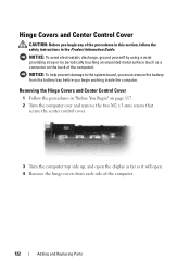
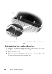
1 2 1 center control cover 2 hinge cover (2) 5 Ease the center control cover up, and remove the cable that attaches it to the system board. Adding and Replacing Parts 123
1 2 1 center control cover 2 hinge cover (2) 5 Ease the center control cover up, and remove the cable that attaches it to the system board. Adding and Replacing Parts 123
Owners Manual
Page 124
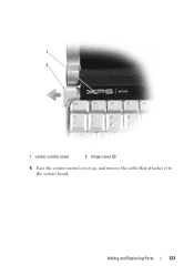
1 2 3 1 center control cover 2 center control cover 2 securing lever cable Replacing the Hinge Covers and Center Control Cover 1 Reconnect the cable that attaches the center control cover to the system board, and snap the center control cover in place. 2 Replace the hinge covers. 3 Turn the computer over and replace the two M2 x 3-mm screws that secure the center control cover to the computer base. 124 Adding and Replacing Parts
1 2 3 1 center control cover 2 center control cover 2 securing lever cable Replacing the Hinge Covers and Center Control Cover 1 Reconnect the cable that attaches the center control cover to the system board, and snap the center control cover in place. 2 Replace the hinge covers. 3 Turn the computer over and replace the two M2 x 3-mm screws that secure the center control cover to the computer base. 124 Adding and Replacing Parts
Owners Manual
Page 125
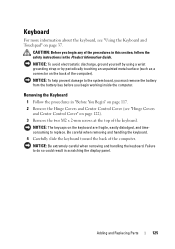
Removing the Keyboard 1 Follow the procedures in the Product Information Guide. Adding and Replacing Parts 125 NOTICE: The keycaps on the keyboard are fragile, easily dislodged, and timeconsuming to do so could result in scratching the display panel. NOTICE: Be ...
Removing the Keyboard 1 Follow the procedures in the Product Information Guide. Adding and Replacing Parts 125 NOTICE: The keycaps on the keyboard are fragile, easily dislodged, and timeconsuming to do so could result in scratching the display panel. NOTICE: Be ...
Owners Manual
Page 126
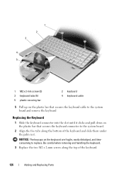
Be careful when removing and handling the keyboard. 3 Replace the two M2 x 2-mm screws along the bottom of the keyboard. 126 Adding and Replacing Parts NOTICE: The keycaps on the plastic bar that secures the keyboard cable to the system board and remove the keyboard Replacing the Keyboard 1 Slide the ...
Be careful when removing and handling the keyboard. 3 Replace the two M2 x 2-mm screws along the bottom of the keyboard. 126 Adding and Replacing Parts NOTICE: The keycaps on the plastic bar that secures the keyboard cable to the system board and remove the keyboard Replacing the Keyboard 1 Slide the ...

Owners Manual
Page 127
... and loosen the three captive screws along with the M2.5 x 5-mm screw. Adding and Replacing Parts 127 NOTICE: If there is a memory module in the connector labeled "DIMM2." Failure to removing the memory module from Dell are intended for information on the system board. Your computer has two user-accessible SODIMM sockets...
... and loosen the three captive screws along with the M2.5 x 5-mm screw. Adding and Replacing Parts 127 NOTICE: If there is a memory module in the connector labeled "DIMM2." Failure to removing the memory module from Dell are intended for information on the system board. Your computer has two user-accessible SODIMM sockets...
Owners Manual
Page 128
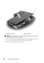
1 2 1 M2.5 x 5-mm screw 2 captive screws (3) NOTICE: To prevent damage to the memory module connector, do not use tools to spread the memory module securing clips. 3 Use your fingertips to carefully spread apart the securing clips on each end of the memory module connector until the module pops up. 4 Remove the module from the connector. 128 Adding and Replacing Parts
1 2 1 M2.5 x 5-mm screw 2 captive screws (3) NOTICE: To prevent damage to the memory module connector, do not use tools to spread the memory module securing clips. 3 Use your fingertips to carefully spread apart the securing clips on each end of the memory module connector until the module pops up. 4 Remove the module from the connector. 128 Adding and Replacing Parts
Owners Manual
Page 129
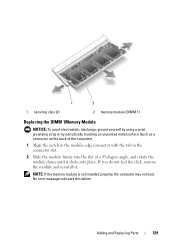
NOTE: If the memory module is not installed properly, the computer may not boot. No error message indicates this failure. Adding and Replacing Parts 129 If you do not feel the click, remove the module and reinstall it clicks into place. 1 2 1 securing clips (2) 2 memory module (DIMM 1) Replacing the DIMM ...
NOTE: If the memory module is not installed properly, the computer may not boot. No error message indicates this failure. Adding and Replacing Parts 129 If you do not feel the click, remove the module and reinstall it clicks into place. 1 2 1 securing clips (2) 2 memory module (DIMM 1) Replacing the DIMM ...
Owners Manual
Page 130
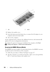
Remove the module cover. 130 Adding and Replacing Parts Removing the DIMM 2 Memory Module The DIMM 2 memory module is located directly above the DIMM 1 memory module located on the bottom of memory installed in "... You Begin" on the computer. To confirm the amount of the computer. 1 Follow the procedures in the computer, click Start → Help and Support→ Dell System Information. As the computer boots, it detects the additional memory and automatically updates the system configuration information. 1 2 1 tab 2 notch 3 Replace the module cover. 4 Insert...
Remove the module cover. 130 Adding and Replacing Parts Removing the DIMM 2 Memory Module The DIMM 2 memory module is located directly above the DIMM 1 memory module located on the bottom of memory installed in "... You Begin" on the computer. To confirm the amount of the computer. 1 Follow the procedures in the computer, click Start → Help and Support→ Dell System Information. As the computer boots, it detects the additional memory and automatically updates the system configuration information. 1 2 1 tab 2 notch 3 Replace the module cover. 4 Insert...
Owners Manual
Page 131
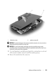
NOTICE: To avoid electrostatic discharge, ground yourself by using a wrist grounding strap or by periodically touching an unpainted metal surface (such as a connector on the back of the computer). 3 Use your fingertips to spread the memory module securing clips. Adding and Replacing Parts 131 1 2 1 2.5x5-mm screw 2 captive screws (3) NOTICE: To prevent damage to the memory module connector, do not use tools to carefully spread apart the securing clips on each end of the memory module connector until the module pops up. 4 Remove the module from the connector.
NOTICE: To avoid electrostatic discharge, ground yourself by using a wrist grounding strap or by periodically touching an unpainted metal surface (such as a connector on the back of the computer). 3 Use your fingertips to spread the memory module securing clips. Adding and Replacing Parts 131 1 2 1 2.5x5-mm screw 2 captive screws (3) NOTICE: To prevent damage to the memory module connector, do not use tools to carefully spread apart the securing clips on each end of the memory module connector until the module pops up. 4 Remove the module from the connector.
Owners Manual
Page 132
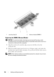
No error message indicates this failure. 132 Adding and Replacing Parts NOTE: If the memory module is not installed properly, the computer may not boot. If you do not feel the click, remove the module and ...
No error message indicates this failure. 132 Adding and Replacing Parts NOTE: If the memory module is not installed properly, the computer may not boot. If you do not feel the click, remove the module and ...


