Fan Removal and Replacement
Page 3
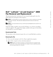
... display assembly with respect to replace the fan, look for a white dot in the Dell Latitude LS and Inspiron 2000 computers. Removing the Fan 1 Save any work in this procedure. Dell Latitude LS and Inspiron 2000 Fan Removal and Replacement 1 This white dot indicates that the fan does... not need to the bottom case should never exceed 180 degrees. www.dell.com | support.dell.com Dell™ Latitude™ LS and Inspiron™ 2000 Fan Removal...
... display assembly with respect to replace the fan, look for a white dot in the Dell Latitude LS and Inspiron 2000 computers. Removing the Fan 1 Save any work in this procedure. Dell Latitude LS and Inspiron 2000 Fan Removal and Replacement 1 This white dot indicates that the fan does... not need to the bottom case should never exceed 180 degrees. www.dell.com | support.dell.com Dell™ Latitude™ LS and Inspiron™ 2000 Fan Removal...

Fan Removal and Replacement
Page 4
www.dell.com | support.dell.com 3 If the computer is clean to prevent scratching the computer cover. Slide the battery bay latch toward the right side of the computer to ... battery assembly from their electrical outlets to push the back side of the battery up and out of the battery bay (see the following figure). 2 Dell Latitude LS and Inspiron 2000 Fan Removal and Replacement NOTICE: Make sure that the work surface is docked, undock the computer. 4 Disconnect the computer and any installed...
www.dell.com | support.dell.com 3 If the computer is clean to prevent scratching the computer cover. Slide the battery bay latch toward the right side of the computer to ... battery assembly from their electrical outlets to push the back side of the battery up and out of the battery bay (see the following figure). 2 Dell Latitude LS and Inspiron 2000 Fan Removal and Replacement NOTICE: Make sure that the work surface is docked, undock the computer. 4 Disconnect the computer and any installed...
Fan Removal and Replacement
Page 5
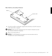
NOTICE: To avoid damaging the microphone, do not put any static electricity that might harm components. 10 Remove the keyboard bezel. NOTICE: While you work, periodically touch the I /O connector on the back of the computer. Dell Latitude LS and Inspiron 2000 Fan Removal and Replacement 3 Main Battery Assembly Removal battery battery latch 9 Ground yourself by touching the unpainted metal surface of an I /O panel to dissipate any objects into the microphone hole (see the following figure).
NOTICE: To avoid damaging the microphone, do not put any static electricity that might harm components. 10 Remove the keyboard bezel. NOTICE: While you work, periodically touch the I /O connector on the back of the computer. Dell Latitude LS and Inspiron 2000 Fan Removal and Replacement 3 Main Battery Assembly Removal battery battery latch 9 Ground yourself by touching the unpainted metal surface of an I /O panel to dissipate any objects into the microphone hole (see the following figure).
Fan Removal and Replacement
Page 6
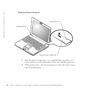
b While pushing down . Lift the keyboard bezel. 4 Dell Latitude LS and Inspiron 2000 Fan Removal and Replacement www.dell.com | support.dell.com Keyboard Bezel Removal keyboard bezel microphone hole keyboard bezel release hole a Place the point of a paper clip, a very small flat-blade screwdriver, or a tool of similar size in the keyboard bezel hole and carefully push down , slide the keyboard bezel to the left until it releases.
b While pushing down . Lift the keyboard bezel. 4 Dell Latitude LS and Inspiron 2000 Fan Removal and Replacement www.dell.com | support.dell.com Keyboard Bezel Removal keyboard bezel microphone hole keyboard bezel release hole a Place the point of a paper clip, a very small flat-blade screwdriver, or a tool of similar size in the keyboard bezel hole and carefully push down , slide the keyboard bezel to the left until it releases.
Fan Removal and Replacement
Page 7
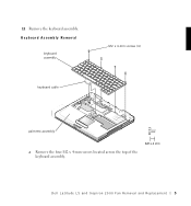
Dell Latitude LS and Inspiron 2000 Fan Removal and Replacement 5 11 Remove the keyboard assembly. Keyboard Assembly Removal keyboard assembly keyboard cable M2 x 4-mm screws (4) palmrest assembly a Remove the four M2 x 4-mm screws located across the top of the keyboard assembly.
Dell Latitude LS and Inspiron 2000 Fan Removal and Replacement 5 11 Remove the keyboard assembly. Keyboard Assembly Removal keyboard assembly keyboard cable M2 x 4-mm screws (4) palmrest assembly a Remove the four M2 x 4-mm screws located across the top of the keyboard assembly.
Fan Removal and Replacement
Page 8
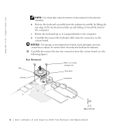
... toward the back of the keyboard in the palmrest assembly. Fan Removal fan M2 x 3.5-mm screws (2) fan wire arrow connector 6 Dell Latitude LS and Inspiron 2000 Fan Removal and Replacement www.dell.com | support.dell.com NOTE: Five metal tabs retain the bottom of the computer. c Rotate the keyboard up and sliding it is perpendicular...
... toward the back of the keyboard in the palmrest assembly. Fan Removal fan M2 x 3.5-mm screws (2) fan wire arrow connector 6 Dell Latitude LS and Inspiron 2000 Fan Removal and Replacement www.dell.com | support.dell.com NOTE: Five metal tabs retain the bottom of the computer. c Rotate the keyboard up and sliding it is perpendicular...
Fan Removal and Replacement
Page 9
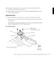
... the computer. The male connector on the system board assembly. Fan Replacement fan M2 x 8-mm screws and washers (2) fan wire arrow connector thermal cooling solution Dell Latitude LS and Inspiron 2000 Fan Removal and Replacement 7
... the computer. The male connector on the system board assembly. Fan Replacement fan M2 x 8-mm screws and washers (2) fan wire arrow connector thermal cooling solution Dell Latitude LS and Inspiron 2000 Fan Removal and Replacement 7
Fan Removal and Replacement
Page 10
... of the keyboard assembly are aligned properly into the palmrest assembly. a Connect the keyboard cable to the bottom assembly. 5 Reinstall the keyboard bezel. www.dell.com | support.dell.com 2 Place the fan in the screw slots on the palmrest assembly. c Ensure that the top screw-hole tabs rest correctly in the bottom.... 3 Reinstall the new M2 x 8-mm screws and washers to secure the fan to the outer edge of the keyboard into the slotted holes in reverse. 8 Dell Latitude LS and Inspiron 2000 Fan Removal and Replacement
... of the keyboard assembly are aligned properly into the palmrest assembly. a Connect the keyboard cable to the bottom assembly. 5 Reinstall the keyboard bezel. www.dell.com | support.dell.com 2 Place the fan in the screw slots on the palmrest assembly. c Ensure that the top screw-hole tabs rest correctly in the bottom.... 3 Reinstall the new M2 x 8-mm screws and washers to secure the fan to the outer edge of the keyboard into the slotted holes in reverse. 8 Dell Latitude LS and Inspiron 2000 Fan Removal and Replacement
Service Manual
Page 9
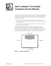
Dell™ Latitude™ LS Portable Computers Service Manual This manual provides instructions for removing and replacing field-replaceable components, assemblies, and subassemblies in reverse order unless otherwise noted. ...of computer left side right side front of the computer. • A part can be replaced by performing the removal procedure in your Dell Latitude portable computer. Computer Orientation support.dell.com Dell Latitude LS Portable Computers Service Manual 1 When the display assembly is open nearly 180 degrees, use a book or something similar to the bottom ...
Dell™ Latitude™ LS Portable Computers Service Manual This manual provides instructions for removing and replacing field-replaceable components, assemblies, and subassemblies in reverse order unless otherwise noted. ...of computer left side right side front of the computer. • A part can be replaced by performing the removal procedure in your Dell Latitude portable computer. Computer Orientation support.dell.com Dell Latitude LS Portable Computers Service Manual 1 When the display assembly is open nearly 180 degrees, use a book or something similar to the bottom ...
Service Manual
Page 10
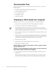
... sure that the computer is turned off the computer and any installed PC Cards. NOTE: Make sure that the work surface is docked in the LS Advanced Port Replicator (APR), undock the computer. 4. Remove the power cable. 6. Disconnect the computer and any work on the computer, perform the following steps: 1. NOTICE... from the computer. 7. Recommended Tools Most of the procedures in this manual require the use of one or more of the battery bay (see Figure 2). 2 Dell Latitude LS Portable Computers Service Manual
... sure that the computer is turned off the computer and any installed PC Cards. NOTE: Make sure that the work surface is docked in the LS Advanced Port Replicator (APR), undock the computer. 4. Remove the power cable. 6. Disconnect the computer and any work on the computer, perform the following steps: 1. NOTICE... from the computer. 7. Recommended Tools Most of the procedures in this manual require the use of one or more of the battery bay (see Figure 2). 2 Dell Latitude LS Portable Computers Service Manual

Service Manual
Page 11
NOTICE: While you work, periodically touch the I /O connector on the back of the correct length. Otherwise, you must use a screw of the computer. support.dell.com Dell Latitude LS Portable Computers Service Manual 3 Screw Identification NOTICE: When reinstalling a screw, you could damage the hardware. battery battery latch Figure 2. Figure 3. Main Battery Assembly Removal 9. Figure 3 ...
NOTICE: While you work, periodically touch the I /O connector on the back of the correct length. Otherwise, you must use a screw of the computer. support.dell.com Dell Latitude LS Portable Computers Service Manual 3 Screw Identification NOTICE: When reinstalling a screw, you could damage the hardware. battery battery latch Figure 2. Figure 3. Main Battery Assembly Removal 9. Figure 3 ...
Service Manual
Page 12
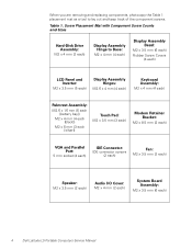
Screw Placement Mat with Component Screw Counts and Sizes Hard-Disk Drive Assembly: M2 x 4 mm (2 each ) 4 Dell Latitude LS Portable Computers Service Manual When you are removing and replacing components, photocopy the Table 1 placement mat as a tool to Base: M2 x 4 mm (4 each) Display Assembly ...
Screw Placement Mat with Component Screw Counts and Sizes Hard-Disk Drive Assembly: M2 x 4 mm (2 each ) 4 Dell Latitude LS Portable Computers Service Manual When you are removing and replacing components, photocopy the Table 1 placement mat as a tool to Base: M2 x 4 mm (4 each) Display Assembly ...
Service Manual
Page 13
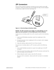
... from them (see Figure 4). While holding the cable in place, close the ZIF connector. Pull gently upward on the movable part of the connector. support.dell.com Dell Latitude LS Portable Computers Service Manual 5 Use a small flat-blade screwdriver to disconnect a cable from a ZIF connector, perform the following steps: 1. To avoid damage, do not...
... from them (see Figure 4). While holding the cable in place, close the ZIF connector. Pull gently upward on the movable part of the connector. support.dell.com Dell Latitude LS Portable Computers Service Manual 5 Use a small flat-blade screwdriver to disconnect a cable from a ZIF connector, perform the following steps: 1. To avoid damage, do not...
Service Manual
Page 14
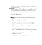
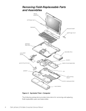
Exploded View-Computer The following subsections provide instructions for removing and replacing field-replaceable parts and assemblies. 6 Dell Latitude LS Portable Computers Service Manual Removing Field-Replaceable Parts and Assemblies display assembly left hinge cover keyboard keyboard bezel right hinge cover palmrest assembly audio EMI shield audio I/O port cover hard-disk drive modem system board assembly speaker fan APR docking doors bottom case assembly main battery Figure 5.
Exploded View-Computer The following subsections provide instructions for removing and replacing field-replaceable parts and assemblies. 6 Dell Latitude LS Portable Computers Service Manual Removing Field-Replaceable Parts and Assemblies display assembly left hinge cover keyboard keyboard bezel right hinge cover palmrest assembly audio EMI shield audio I/O port cover hard-disk drive modem system board assembly speaker fan APR docking doors bottom case assembly main battery Figure 5.
Service Manual
Page 15
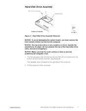
NOTICE: Make sure that the work surface is located on the right side of the computer. 2. support.dell.com Dell Latitude LS Portable Computers Service Manual 7 Turn the computer over, and remove the two M2 x 4-mm screws from the bottom of computer Figure 6. Hard-Disk Drive Assembly ...
NOTICE: Make sure that the work surface is located on the right side of the computer. 2. support.dell.com Dell Latitude LS Portable Computers Service Manual 7 Turn the computer over, and remove the two M2 x 4-mm screws from the bottom of computer Figure 6. Hard-Disk Drive Assembly ...

Service Manual
Page 16
... you service the computer. NOTICE: To avoid damaging the microphone, do not put any objects into the microphone hole (see Figure 7). 2. Lift the keyboard bezel. 8 Dell Latitude LS Portable Computers Service Manual While pushing down (see Figure 7). 1. Keyboard Bezel keyboard bezel microphone hole keyboard bezel release hole Figure 7.
... you service the computer. NOTICE: To avoid damaging the microphone, do not put any objects into the microphone hole (see Figure 7). 2. Lift the keyboard bezel. 8 Dell Latitude LS Portable Computers Service Manual While pushing down (see Figure 7). 1. Keyboard Bezel keyboard bezel microphone hole keyboard bezel release hole Figure 7.
Service Manual
Page 17
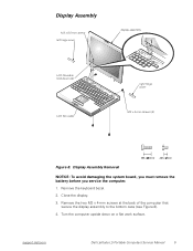
... at the back of the computer that secure the display assembly to the bottom case (see Figure 8). 4. Remove the keyboard bezel. 2. Close the display. 3. support.dell.com Dell Latitude LS Portable Computers Service Manual 9
... at the back of the computer that secure the display assembly to the bottom case (see Figure 8). 4. Remove the keyboard bezel. 2. Close the display. 3. support.dell.com Dell Latitude LS Portable Computers Service Manual 9

Service Manual
Page 18
.... 10. Remove the M2 x 8.5-mm screw that secures the LCD flex-cable hold-down clip and the LCD flex-cable connector to close completely. 10 Dell Latitude LS Portable Computers Service Manual Insert the left and right hinge posts into the holes at the left hinge cover and an R is stamped on the...
.... 10. Remove the M2 x 8.5-mm screw that secures the LCD flex-cable hold-down clip and the LCD flex-cable connector to close completely. 10 Dell Latitude LS Portable Computers Service Manual Insert the left and right hinge posts into the holes at the left hinge cover and an R is stamped on the...

Service Manual
Page 19
... two screws that secure the display assembly to squeeze the display assembly and the bottom assembly together, so the screw holes align in step 6. 9. support.dell.com Dell Latitude LS Portable Computers Service Manual 11 6. Reinstall the two M2 x 4-mm screws that you installed in the base assembly and the hinge posts.
... two screws that secure the display assembly to squeeze the display assembly and the bottom assembly together, so the screw holes align in step 6. 9. support.dell.com Dell Latitude LS Portable Computers Service Manual 11 6. Reinstall the two M2 x 4-mm screws that you installed in the base assembly and the hinge posts.
Service Manual
Page 20
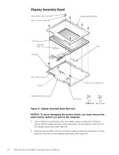
... out of the six screw holes located along the top and bottom of the bezel on the front of the display assembly (see Figure 9). 12 Dell Latitude LS Portable Computers Service Manual Display Assembly Bezel Removal NOTICE: To avoid damaging the system board, you must remove the main battery before you service the...
... out of the six screw holes located along the top and bottom of the bezel on the front of the display assembly (see Figure 9). 12 Dell Latitude LS Portable Computers Service Manual Display Assembly Bezel Removal NOTICE: To avoid damaging the system board, you must remove the main battery before you service the...


