
Service Manual
Page 3
Contents Chapter 1 System Overview 1-1 System Features 1-1 Physical Description 1-2 Status Display 1-3 Keyboard Indicators 1-3 CD-ROM/Hard-Disk Drive Indicator 1-3 Diskette-Drive Access Indicator 1-4 PC Card Indicator 1-4 AC Power Indicator 1-4 Battery Activity Indicator 1-4 Battery Status Indicator 1-4 Battery Charge Gauge 1-5 Password 1-5 ...
Contents Chapter 1 System Overview 1-1 System Features 1-1 Physical Description 1-2 Status Display 1-3 Keyboard Indicators 1-3 CD-ROM/Hard-Disk Drive Indicator 1-3 Diskette-Drive Access Indicator 1-4 PC Card Indicator 1-4 AC Power Indicator 1-4 Battery Activity Indicator 1-4 Battery Status Indicator 1-4 Battery Charge Gauge 1-5 Password 1-5 ...
Service Manual
Page 12
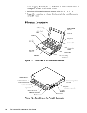
...the Portable Computer infrared port serial port connector parallel port connector monitor connector I /O panel. However, the CD-ROM must be in the computer before or during boot in order for the drivers to load. • Built-in serial infrared transmitter/receiver, effective to 1 .../speakers connector external microphone connector AC adapter connector PC Card slots Figure 1-2. Front View of the Portable Computer 1-2 Dell Latitude LM Systems Service Manual warm swapping. Physical Description LCD assembly status display panel keyboard hard-disk drive bay power/suspend indicator...
...the Portable Computer infrared port serial port connector parallel port connector monitor connector I /O panel. However, the CD-ROM must be in the computer before or during boot in order for the drivers to load. • Built-in serial infrared transmitter/receiver, effective to 1 .../speakers connector external microphone connector AC adapter connector PC Card slots Figure 1-2. Front View of the Portable Computer 1-2 Dell Latitude LM Systems Service Manual warm swapping. Physical Description LCD assembly status display panel keyboard hard-disk drive bay power/suspend indicator...

Service Manual
Page 40
... over and remove screws HD1 and HD2. Remove the hard-disk drive assembly. This feature is sometimes called hot swapping. However, the CD-ROM must be inserted or removed while the computer is in order for the drivers to replace the lithium ion battery or diskette drive without... are 10 mm) 10mm 6. Options Bay Lock and Latch 4-4 Dell Latitude LM Systems Service Manual With the computer facing you, slide the hard-disk drive cover to the lock groove). The CD-ROM can be in the computer before or during boot in suspend mode. handle cover HD1 HD2 Figure 4-4. This feature...
... over and remove screws HD1 and HD2. Remove the hard-disk drive assembly. This feature is sometimes called hot swapping. However, the CD-ROM must be inserted or removed while the computer is in order for the drivers to replace the lithium ion battery or diskette drive without... are 10 mm) 10mm 6. Options Bay Lock and Latch 4-4 Dell Latitude LM Systems Service Manual With the computer facing you, slide the hard-disk drive cover to the lock groove). The CD-ROM can be in the computer before or during boot in suspend mode. handle cover HD1 HD2 Figure 4-4. This feature...

Service Manual
Page 83
..., 3-1 list of, 3-2 board assembly illustrated, 4-43 removal, 4-43 boot routine observing when troubleshooting, 2-3 bottom assembly, 4-39 C cache board removal, 4-45 Caps Lock indicator, 1-3 CD-ROM disassembly, 4-21 CD-ROM/Hard-Disk Drive indicator, 1-3 computer features, 1-1 illustrated, 1-2 power conservation modes, 1-6 technical specifications, 1-8 computer power, 1-6 D Dell diagnostics, 3-6 dimming the display, 1-6 diskette drive bay, 1-2 diskette drive disassembly...
..., 3-1 list of, 3-2 board assembly illustrated, 4-43 removal, 4-43 boot routine observing when troubleshooting, 2-3 bottom assembly, 4-39 C cache board removal, 4-45 Caps Lock indicator, 1-3 CD-ROM disassembly, 4-21 CD-ROM/Hard-Disk Drive indicator, 1-3 computer features, 1-1 illustrated, 1-2 power conservation modes, 1-6 technical specifications, 1-8 computer power, 1-6 D Dell diagnostics, 3-6 dimming the display, 1-6 diskette drive bay, 1-2 diskette drive disassembly...

Reference and Troubleshooting Guide
Page 11
Contents Chapter 1 Introduction 1-1 Hardware Features 1-2 Software Features 1-3 Accessing Online Documentation 1-4 Available Options 1-4 Getting Help 1-4 Chapter 2 Customizing System Features 2-1 System Utilities 2-1 Setup Program 2-2 Accessing the Setup Program 2-2 Main Menu Options 2-2 Date 2-3 Time 2-3 Hard-Disk Drive 0 2-3 Boot Sequence 2-3 Diskette A 2-4 Total Memory 2-4 Video Memory 2-4 Peripherals Menu Options 2-4 Integrated Peripherals 2-4 Serial Port 2-4 Infrared 2-5 Parallel Mode 2-6 Diskette Mode 2-6 Video Mode 2-6 Touch Pad 2-6 CD-ROM Drive Speed 2-6 xiii
Contents Chapter 1 Introduction 1-1 Hardware Features 1-2 Software Features 1-3 Accessing Online Documentation 1-4 Available Options 1-4 Getting Help 1-4 Chapter 2 Customizing System Features 2-1 System Utilities 2-1 Setup Program 2-2 Accessing the Setup Program 2-2 Main Menu Options 2-2 Date 2-3 Time 2-3 Hard-Disk Drive 0 2-3 Boot Sequence 2-3 Diskette A 2-4 Total Memory 2-4 Video Memory 2-4 Peripherals Menu Options 2-4 Integrated Peripherals 2-4 Serial Port 2-4 Infrared 2-5 Parallel Mode 2-6 Diskette Mode 2-6 Video Mode 2-6 Touch Pad 2-6 CD-ROM Drive Speed 2-6 xiii

Reference and Troubleshooting Guide
Page 37
...When you can hear the hard-disk drive spin up, and the computer tries to access the boot files from Dell. The CD-ROM/hard-disk drive access indicator The CD-ROM/hard-disk drive access indicator should appear in the status display when data is important in ...Keyboard Test Group in this chapter. Listen for instructions, see Chapter 4, "Running the Dell Diagnostics." Call Dell for technical assistance. (See Chapter 5, "Getting Help," for the indications described in this chapter. If the CD-ROM/hard-disk drive access indicator does not appear, see the next subsection, "...
...When you can hear the hard-disk drive spin up, and the computer tries to access the boot files from Dell. The CD-ROM/hard-disk drive access indicator The CD-ROM/hard-disk drive access indicator should appear in the status display when data is important in ...Keyboard Test Group in this chapter. Listen for instructions, see Chapter 4, "Running the Dell Diagnostics." Call Dell for technical assistance. (See Chapter 5, "Getting Help," for the indications described in this chapter. If the CD-ROM/hard-disk drive access indicator does not appear, see the next subsection, "...

Reference and Troubleshooting Guide
Page 49
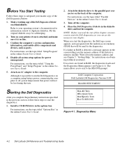
... an explanation of the Diagnostics Checklist found in the status display panel during the boot routine? Insert a bootable diskette into drive A, and reboot the computer. Install the CD-ROM drive in the Settings folder). Go to experience trouble, call Dell for technical assistance. (See Chapter 5, "Getting Help," for instructions.) No. Type d: and press...
... an explanation of the Diagnostics Checklist found in the status display panel during the boot routine? Insert a bootable diskette into drive A, and reboot the computer. Install the CD-ROM drive in the Settings folder). Go to experience trouble, call Dell for technical assistance. (See Chapter 5, "Getting Help," for instructions.) No. Type d: and press...
Reference and Troubleshooting Guide
Page 58
...CD-ROM drive in RAM, the diagnostics loads and the Diagnostics Menu appears (see Figure 4-1). For instructions, see the menus on your operating system's documentation for instructions on your master copy of the Dell...the back of the defective memory module. Dell Computer Corporation Dell Latitude LM Diagnostics Version X.XX DIAGNOSTICS MENU Starting the Dell Diagnostics After you complete the preliminary instructions ...instructions, see the topic titled "Setup Program" in the diskette drive, and boot the computer. For instructions, see Chapter 5, "Getting Help," for information on...
...CD-ROM drive in RAM, the diagnostics loads and the Diagnostics Menu appears (see Figure 4-1). For instructions, see the menus on your operating system's documentation for instructions on your master copy of the Dell...the back of the defective memory module. Dell Computer Corporation Dell Latitude LM Diagnostics Version X.XX DIAGNOSTICS MENU Starting the Dell Diagnostics After you complete the preliminary instructions ...instructions, see the topic titled "Setup Program" in the diskette drive, and boot the computer. For instructions, see Chapter 5, "Getting Help," for information on...

Reference and Troubleshooting Guide
Page 60
... area does not list the names of all the components or devices you know are part of the Dell Diagnostics Confirming the System Configuration Information When you boot the computer from your diagnostics diskette, the diagnostics checks your printer is attached to look for incoming information...809MB, 1571 Cyl, 16 Hd, 63 Sec 1 NONE 2 NONE 3 NONE Test Limits About Key-Help Quit Press Q to Quit * On the Dell Latitude LM, a CD-ROM drive installed in the System Configuration area on the main screen. Main Screen of the computer. Instead, the printer is recognized as a parallel port...
... area does not list the names of all the components or devices you know are part of the Dell Diagnostics Confirming the System Configuration Information When you boot the computer from your diagnostics diskette, the diagnostics checks your printer is attached to look for incoming information...809MB, 1571 Cyl, 16 Hd, 63 Sec 1 NONE 2 NONE 3 NONE Test Limits About Key-Help Quit Press Q to Quit * On the Dell Latitude LM, a CD-ROM drive installed in the System Configuration area on the main screen. Main Screen of the computer. Instead, the printer is recognized as a parallel port...

Reference and Troubleshooting Guide
Page 123
... or credit, 5-4 audio functions troubleshooting, 3-22 Audio Test Group Dell diagnostics, 4-20 AutoTech service, 5-3 B basic input/output system. See PC Cards cautions, x CD-ROM drive about , 3-6 BIOS, 1-3 boot routine indications, 3-3 bulletin board service. See video tests, Text..., v connectors location, 1-2 troubleshooting, 3-2 Index 1 See TechConnect BBS C cables shielded cables, C-1 troubleshooting, 3-2 cache memory, 1-3 calling Dell, 5-7 card. See video tests, Text Mode Character Test character set test. See video tests, Text Mode Character Test color attributes test. See...
... or credit, 5-4 audio functions troubleshooting, 3-22 Audio Test Group Dell diagnostics, 4-20 AutoTech service, 5-3 B basic input/output system. See PC Cards cautions, x CD-ROM drive about , 3-6 BIOS, 1-3 boot routine indications, 3-3 bulletin board service. See video tests, Text..., v connectors location, 1-2 troubleshooting, 3-2 Index 1 See TechConnect BBS C cables shielded cables, C-1 troubleshooting, 3-2 cache memory, 1-3 calling Dell, 5-7 card. See video tests, Text Mode Character Test character set test. See video tests, Text Mode Character Test color attributes test. See...


