
Dell Owners Manual
Page 3
... Installing the ExpressCard...13 Removing the Battery...13 Installing the Battery...13 Removing the Base Cover...14 Installing the Base Cover...14 Removing the Memory...14 Installing the Memory...15 Removing the Hard Drive...15 Installing the Hard Drive...16 Removing the Optical Drive...16 Installing the Optical Drive...17 Removing the...
... Installing the ExpressCard...13 Removing the Battery...13 Installing the Battery...13 Removing the Base Cover...14 Installing the Base Cover...14 Removing the Memory...14 Installing the Memory...15 Removing the Hard Drive...15 Installing the Hard Drive...16 Removing the Optical Drive...16 Installing the Optical Drive...17 Removing the...

Dell Owners Manual
Page 11
base corner caps 2. SD card 6. ExpressCard slot 7. WLAN card 9. optical drive 8. coin-cell battery 10. System Overview Figure 1. heatsink assembly 4. Back View - WWAN card 11 Back Cover Removed 1. memory module 5. 2 Removing and Installing Components This section provides detailed information on how to remove or install the components from your computer. power connector 3.
base corner caps 2. SD card 6. ExpressCard slot 7. WLAN card 9. optical drive 8. coin-cell battery 10. System Overview Figure 1. heatsink assembly 4. Back View - WWAN card 11 Back Cover Removed 1. memory module 5. 2 Removing and Installing Components This section provides detailed information on how to remove or install the components from your computer. power connector 3.

Dell Owners Manual
Page 14
... Inside Your Computer. 2. Tighten the screws to secure the base cover to the computer. Removing the Memory 1. Remove the screws that secure the base cover to the computer. 3. Pry the securing clips away from the memory module until it from its connector on the computer. 2. Follow the procedures in Before Working Inside... Base Cover 1. Remove: a) battery b) base cover 3. Install the battery. 4. Removing the Base Cover 1. Lift the base cover and remove it pops-up and remove the memory module from the computer. Follow the procedures in After Working Inside Your Computer.
... Inside Your Computer. 2. Tighten the screws to secure the base cover to the computer. Removing the Memory 1. Remove the screws that secure the base cover to the computer. 3. Pry the securing clips away from the memory module until it from its connector on the computer. 2. Follow the procedures in Before Working Inside... Base Cover 1. Remove: a) battery b) base cover 3. Install the battery. 4. Removing the Base Cover 1. Lift the base cover and remove it pops-up and remove the memory module from the computer. Follow the procedures in After Working Inside Your Computer.

Dell Owners Manual
Page 15
... secures the hard-drive caddy to the hard drive. Slide the hard drive out of the computer. 4. Flex the hard-drive isolation. Insert the memory into the memory socket. 2. Install: a) base cover b) battery 4. Remove the hard-drive caddy from the hard drive. 15 Follow the procedures in Before Working Inside Your Computer... screw that secure the hard drive to the system board. 3. Follow the procedures in After Working Inside Your Computer. Removing the Hard Drive 1. Installing the Memory 1. Press the securing clips to secure the...
... secures the hard-drive caddy to the hard drive. Slide the hard drive out of the computer. 4. Flex the hard-drive isolation. Insert the memory into the memory socket. 2. Install: a) base cover b) battery 4. Remove the hard-drive caddy from the hard drive. 15 Follow the procedures in Before Working Inside Your Computer... screw that secure the hard drive to the system board. 3. Follow the procedures in After Working Inside Your Computer. Removing the Hard Drive 1. Installing the Memory 1. Press the securing clips to secure the...

Dell Owners Manual
Page 33
.... 2. Remove: a) SD Card b) ExpressCard c) battery d) keyboard trim e) keyboard f) hard drive g) optical drive h) display-hinge cover i) base cover j) base corner caps k) power connector l) coin-cell battery m) memory n) WLAN card o) WWAN card p) heatsink assembly q) processor r) palmrest assembly s) ExpressCard cage 3. Follow the procedures in After Working Inside Your Computer. Disconnect the coin-cell battery...
.... 2. Remove: a) SD Card b) ExpressCard c) battery d) keyboard trim e) keyboard f) hard drive g) optical drive h) display-hinge cover i) base cover j) base corner caps k) power connector l) coin-cell battery m) memory n) WLAN card o) WWAN card p) heatsink assembly q) processor r) palmrest assembly s) ExpressCard cage 3. Follow the procedures in After Working Inside Your Computer. Disconnect the coin-cell battery...

Dell Owners Manual
Page 35
Connect the following cables to secure the system board. 3. Removing the Speakers 1. Install: a) ExpressCard cage b) palmrest assembly c) processor d) heatsink assembly e) WWAN f) WLAN card g) memory h) coin-cell battery i) power connector j) base corner caps k) base cover l) display-hinge cover m) optical drive n) hard drive o) keyboard trim p) keyboard q) battery r) ExpressCard s) SD card 5. Connect ...
Connect the following cables to secure the system board. 3. Removing the Speakers 1. Install: a) ExpressCard cage b) palmrest assembly c) processor d) heatsink assembly e) WWAN f) WLAN card g) memory h) coin-cell battery i) power connector j) base corner caps k) base cover l) display-hinge cover m) optical drive n) hard drive o) keyboard trim p) keyboard q) battery r) ExpressCard s) SD card 5. Connect ...

Dell Owners Manual
Page 36
b) ExpressCard c) battery d) keyboard trim e) keyboard f) hard drive g) optical drive h) display-hinge cover i) base cover j) base corner caps k) palmrest assembly l) power connector m) coin-cell battery n) memory o) WLAN card p) WWAN card q) heatsink assembly r) processor s) ExpressCard cage t) display assembly u) system board 3. Remove the screws that secure the speakers to secure the speakers. 3. Align ...
b) ExpressCard c) battery d) keyboard trim e) keyboard f) hard drive g) optical drive h) display-hinge cover i) base cover j) base corner caps k) palmrest assembly l) power connector m) coin-cell battery n) memory o) WLAN card p) WWAN card q) heatsink assembly r) processor s) ExpressCard cage t) display assembly u) system board 3. Remove the screws that secure the speakers to secure the speakers. 3. Align ...

Dell Owners Manual
Page 37
...Remove: a) SD card b) express card c) battery d) keyboard trim e) keyboard f) hard drive g) optical drive h) display-hinge cover i) base cover j) memory k) WLAN card l) WWAN card m) base corner covers n) palmrest o) speaker p) display assembly q) system board 3. Follow the procedures in Before Working Inside ... the system board and remove the screws that secure the I /O Board 1. Follow the procedures in After Working Inside Your Computer. h) memory i) coin-cell battery j) power connector k) palmrest assembly l) base corner caps m) base cover n) display-hinge cover o) optical drive p) ...
...Remove: a) SD card b) express card c) battery d) keyboard trim e) keyboard f) hard drive g) optical drive h) display-hinge cover i) base cover j) memory k) WLAN card l) WWAN card m) base corner covers n) palmrest o) speaker p) display assembly q) system board 3. Follow the procedures in Before Working Inside ... the system board and remove the screws that secure the I /O Board 1. Follow the procedures in After Working Inside Your Computer. h) memory i) coin-cell battery j) power connector k) palmrest assembly l) base corner caps m) base cover n) display-hinge cover o) optical drive p) ...

Dell Owners Manual
Page 38
Install: a) system board b) display assembly c) speaker d) palmrest e) base corner covers f) WWAN card g) WLAN card h) memory i) base cover j) display-hinge cover k) optical drive l) keyboard m) keyboard trim n) hard drive o) battery p) express cage q) SD card 5. Removing the Display Assembly 1. Remove: a) battery b) keyboard trim c) ...
Install: a) system board b) display assembly c) speaker d) palmrest e) base corner covers f) WWAN card g) WLAN card h) memory i) base cover j) display-hinge cover k) optical drive l) keyboard m) keyboard trim n) hard drive o) battery p) express cage q) SD card 5. Removing the Display Assembly 1. Remove: a) battery b) keyboard trim c) ...

Dell Owners Manual
Page 48
... the standard graphics browser only. System Setup Options NOTE: Depending on your computer. • System Information - Displays Memory Installed, Memory Available, Memory Speed, Memory Channel Mode, Memory Technology, DIMM A Size, DIMM B Size • Processor Information - Expands or collapses a drop‐down list... Version, Service Tag, Asset Tag, Ownership Tag, Ownership Date, Manufacture Date, and the Express Service Code. • Memory Information - Moves to the next focus area. Displays Processor Type, Core Count, Processor ID, Current Clock Speed, Minimum Clock...
... the standard graphics browser only. System Setup Options NOTE: Depending on your computer. • System Information - Displays Memory Installed, Memory Available, Memory Speed, Memory Channel Mode, Memory Technology, DIMM A Size, DIMM B Size • Processor Information - Expands or collapses a drop‐down list... Version, Service Tag, Asset Tag, Ownership Tag, Ownership Date, Manufacture Date, and the Express Service Code. • Memory Information - Moves to the next focus area. Displays Processor Type, Core Count, Processor ID, Current Clock Speed, Minimum Clock...

Dell Owners Manual
Page 62
...Lights Storage LED Power LED Wireless LED Fault Description Blinking Solid Solid A possible processor failure has occurred. Solid Blinking Solid The memory modules are installed/detected. The device status LEDs are used to the system. Blinking Off Blinking The USB controller encountered a ... with steady white light Constantly blinking amber light Light off White light on An unauthenticated or unsupported non-Dell AC adapter is attached to initialize or memory is connected to an electrical outlet, the battery light operates as a diagnostic tool when there's a ...
...Lights Storage LED Power LED Wireless LED Fault Description Blinking Solid Solid A possible processor failure has occurred. Solid Blinking Solid The memory modules are installed/detected. The device status LEDs are used to the system. Blinking Off Blinking The USB controller encountered a ... with steady white light Constantly blinking amber light Light off White light on An unauthenticated or unsupported non-Dell AC adapter is attached to initialize or memory is connected to an electrical outlet, the battery light operates as a diagnostic tool when there's a ...

Dell Owners Manual
Page 63
Memory Feature Memory connector Memory capacity Memory type Minimum memory Maximum memory Specification Intel Core i5 / i7 series 3 MB and 4MB Specification Two SODIMM slots 1 GB, 2 GB, 4 GB, or 8 GB DDR3L SDRAM (1600 MHz) 2 GB 16 GB ...
Memory Feature Memory connector Memory capacity Memory type Minimum memory Maximum memory Specification Intel Core i5 / i7 series 3 MB and 4MB Specification Two SODIMM slots 1 GB, 2 GB, 4 GB, or 8 GB DDR3L SDRAM (1600 MHz) 2 GB 16 GB ...

Dell Owners Manual
Page 65
.... Display Feature Type Dimensions: Height Width Diagonal Active area (X/Y) Maximum resolution Maximum Brightness Refresh rate Minimum Viewing Angles: Horizontal Vertical Pixel pitch Table 26. Features Memory card reader Micro Subscriber Identity Module (uSIM) card Docking port Table 24.
.... Display Feature Type Dimensions: Height Width Diagonal Active area (X/Y) Maximum resolution Maximum Brightness Refresh rate Minimum Viewing Angles: Horizontal Vertical Pixel pitch Table 26. Features Memory card reader Micro Subscriber Identity Module (uSIM) card Docking port Table 24.
Statement of Volatility
Page 1
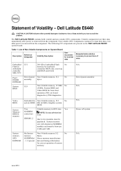
... to hardware or loss of panel assembly N/A N/A Power off system N/A June 2013 Table 1. The Dell Latitude E6440 contains both volatile and non-volatile (NV) components. Video BIOS Embedded in text. System memory SPD EEPROM On System Non Volatile memory 512 No memory Bytes. Volatile components lose their data even after power is removed from the component...
... to hardware or loss of panel assembly N/A N/A Power off system N/A June 2013 Table 1. The Dell Latitude E6440 contains both volatile and non-volatile (NV) components. Video BIOS Embedded in text. System memory SPD EEPROM On System Non Volatile memory 512 No memory Bytes. Volatile components lose their data even after power is removed from the component...

Statement of Volatility
Page 2
...off state. SMSC is removed from the system. frame buffer For UMA platform: Using system memory Volatile memory in this text: Dell™, the DELL logo, OptiPlex™ are trademarks of -day information. 2013 Dell Inc. Primary power loss (unplugging the power cord and removing the battery) destroys all ...on the system configuration and time-of Dell Inc. No 2 GB GDDR5 for discrete graphics systems. For E6540 DSC platform: UV3, UV4, UV5, UV6, UV7, UV8, UV9, UV10, For E6440 DSC platform: UV3, UV4, UV5, UV6, Intel ME U52 Firmware Non Volatile memory, 32 Mbit No (4 MB), ...
...off state. SMSC is removed from the system. frame buffer For UMA platform: Using system memory Volatile memory in this text: Dell™, the DELL logo, OptiPlex™ are trademarks of -day information. 2013 Dell Inc. Primary power loss (unplugging the power cord and removing the battery) destroys all ...on the system configuration and time-of Dell Inc. No 2 GB GDDR5 for discrete graphics systems. For E6540 DSC platform: UV3, UV4, UV5, UV6, UV7, UV8, UV9, UV10, For E6440 DSC platform: UV3, UV4, UV5, UV6, Intel ME U52 Firmware Non Volatile memory, 32 Mbit No (4 MB), ...


