E-Family Re-Image Guide
Page 12
... POST so that it can be used by the Operating System • Deactivate (Default) = The TPM will be deactivated • Activate = The TPM will not turn on the TPM during POST. E-Family Reimage "How-To" Guide TPM Security: These options enable and configure the Trusted Platform Module (TPM). The TPM will... information stored in the BIOS Setup program o Security TPM Security • TPM Security: • Disabled (Default): The BIOS will be enabled in the TPM Dell Confidential
... POST so that it can be used by the Operating System • Deactivate (Default) = The TPM will be deactivated • Activate = The TPM will not turn on the TPM during POST. E-Family Reimage "How-To" Guide TPM Security: These options enable and configure the Trusted Platform Module (TPM). The TPM will... information stored in the BIOS Setup program o Security TPM Security • TPM Security: • Disabled (Default): The BIOS will be enabled in the TPM Dell Confidential
Setup Features and Information Techsheet
Page 3
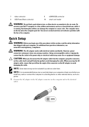
... or the computer. NOTE: Some devices may cause fire or equipment damage. Fan noise is running. For additional best practices information, see www.dell.com/regulatory_compliance. Do not store your computer at least once before you disconnect the AC adapter cable from the computer, grasp the connector, not...damage the computer or cause a fire. CAUTION: When you install any of the connector on and shut down your Dell™ computer in the air vents. The computer turns on the computer and to the power strip or electrical outlet may not be included if you begin any cards ...
... or the computer. NOTE: Some devices may cause fire or equipment damage. Fan noise is running. For additional best practices information, see www.dell.com/regulatory_compliance. Do not store your computer at least once before you disconnect the AC adapter cable from the computer, grasp the connector, not...damage the computer or cause a fire. CAUTION: When you install any of the connector on and shut down your Dell™ computer in the air vents. The computer turns on the computer and to the power strip or electrical outlet may not be included if you begin any cards ...

Setup Features and Information Techsheet
Page 5
... may vary by region. Video NOTE: Your Dell™ computer has both integrated and discrete video options. Video type: integrated and discrete on the computer. For more information regarding the configuration of your computer. 5 Open the computer display and press the power button to turn on system board, hardware accelerated Data bus...
... may vary by region. Video NOTE: Your Dell™ computer has both integrated and discrete video options. Video type: integrated and discrete on the computer. For more information regarding the configuration of your computer. 5 Open the computer display and press the power button to turn on system board, hardware accelerated Data bus...
Replacing the System Board
Page 2
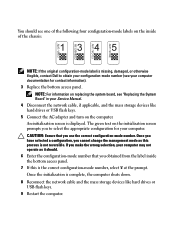
... 8 Reconnect the network cable and the mass storage devices like hard drives or USB flash keys. 5 Connect the AC adapter and turn on the computer. Once you have selected a configuration, you cannot change the management mode as it should see your computer documentation for ...-mode number (see one of the chassis: NOTE: If the original configuration-mode label is missing, damaged, or otherwise illegible, contact Dell to select the appropriate configuration for contact information). 3 Replace the bottom access panel. Once the initialization is displayed. CAUTION: Ensure that ...
... 8 Reconnect the network cable and the mass storage devices like hard drives or USB flash keys. 5 Connect the AC adapter and turn on the computer. Once you have selected a configuration, you cannot change the management mode as it should see your computer documentation for ...-mode number (see one of the chassis: NOTE: If the original configuration-mode label is missing, damaged, or otherwise illegible, contact Dell to select the appropriate configuration for contact information). 3 Replace the bottom access panel. Once the initialization is displayed. CAUTION: Ensure that ...

Replacing the System Board
Page 3
NOTE: The battery light on . NOTE: Latitude and Dell Precision E-Series Workstation computers configured with iAMT® receive this error. Programming the Service Tag After replacing the system board for Latitude E5400, E5500, and Dell Precision M6400 Mobile Workstations, you need to enter the system setup ...program. 2 Enter the correct Service Tag. 3 Perform one of the following message is not connected, turn the computer off, connect the ...
NOTE: The battery light on . NOTE: Latitude and Dell Precision E-Series Workstation computers configured with iAMT® receive this error. Programming the Service Tag After replacing the system board for Latitude E5400, E5500, and Dell Precision M6400 Mobile Workstations, you need to enter the system setup ...program. 2 Enter the correct Service Tag. 3 Perform one of the following message is not connected, turn the computer off, connect the ...
Service Manual
Page 4
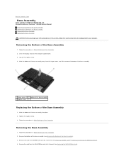
Close the display and turn the computer upside down. 3. Slide the bottom of the base assembly away from the WLAN/WiMax card slot, if present (see Removing the WLAN/WiMax Card). Remove the card from the hinge covers, and lift to Contents Page Base Assembly Dell™ Latitude™ E6400 and E6400 ATG and Mobile Workstation...
Close the display and turn the computer upside down. 3. Slide the bottom of the base assembly away from the WLAN/WiMax card slot, if present (see Removing the WLAN/WiMax Card). Remove the card from the hinge covers, and lift to Contents Page Base Assembly Dell™ Latitude™ E6400 and E6400 ATG and Mobile Workstation...
Service Manual
Page 10
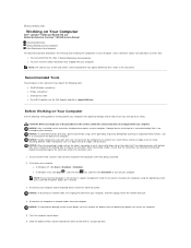
...connector and/or the connector's pins. 1. NOTICE: To avoid electrostatic discharge, ground yourself by its strain-relief loop, not on a card. Turn the computer upside down the computer using a wrist grounding strap or by periodically touching an unpainted metal surface, such as a processor by its edges... flat and clean to prevent the computer cover from the computer. Back to Contents Page Working on Your Computer Dell™ Latitude™ E6400 and E6400 ATG and Mobile Workstation Precision™ M2400 Service Manual Recommended Tools Before Working on Your Computer After Working on ...
...connector and/or the connector's pins. 1. NOTICE: To avoid electrostatic discharge, ground yourself by its strain-relief loop, not on a card. Turn the computer upside down the computer using a wrist grounding strap or by periodically touching an unpainted metal surface, such as a processor by its edges... flat and clean to prevent the computer cover from the computer. Back to Contents Page Working on Your Computer Dell™ Latitude™ E6400 and E6400 ATG and Mobile Workstation Precision™ M2400 Service Manual Recommended Tools Before Working on Your Computer After Working on ...
Service Manual
Page 11
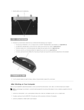
...damage to ground the system board. Do not use only the battery designed for other Dell computers. 1. before working on your battery slice or on support.dell.com. l To remove a port cover from the E6400 ATG, lift up , open the display, and press the power button to the ...computer, use batteries designed for this particular Dell computer. 7. Disconnect any external devices and remove any installed cards, such as an ExpressCard. 2. Turn the computer topside up and ease the...
...damage to ground the system board. Do not use only the battery designed for other Dell computers. 1. before working on your battery slice or on support.dell.com. l To remove a port cover from the E6400 ATG, lift up , open the display, and press the power button to the ...computer, use batteries designed for this particular Dell computer. 7. Disconnect any external devices and remove any installed cards, such as an ExpressCard. 2. Turn the computer topside up and ease the...

Service Manual
Page 12
Turn on your computer and all attached devices to Contents Page Slide the battery into the battery bay until it clicks into place. 5. Back to their electrical outlets. 6. 4. Connect your computer. Replace the battery.
Turn on your computer and all attached devices to Contents Page Slide the battery into the battery bay until it clicks into place. 5. Back to their electrical outlets. 6. 4. Connect your computer. Replace the battery.
Service Manual
Page 13
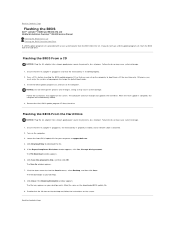
... Double-click the file icon on the desktop and follow the instructions on the computer. 3. Back to Contents Page Flashing the BIOS Dell™ Latitude™ E6400 and E6400 ATG and Mobile Workstation Precision™ M2400 Service Manual Flashing the BIOS From a CD Flashing the BIOS From the Hard Drive If ... for your desktop and is attached. 2. Back to Contents Page Failure to prevent a loss of power. Doing so may cause system damage. 1. Turn on the screen. If you must enter the system setup program to your desktop. 8. Flashing the BIOS From a CD NOTICE: Plug the AC ...
... Double-click the file icon on the desktop and follow the instructions on the computer. 3. Back to Contents Page Flashing the BIOS Dell™ Latitude™ E6400 and E6400 ATG and Mobile Workstation Precision™ M2400 Service Manual Flashing the BIOS From a CD Flashing the BIOS From the Hard Drive If ... for your desktop and is attached. 2. Back to Contents Page Failure to prevent a loss of power. Doing so may cause system damage. 1. Turn on the screen. If you must enter the system setup program to your desktop. 8. Flashing the BIOS From a CD NOTICE: Plug the AC ...
Service Manual
Page 19
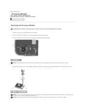
...processor module NOTICE: To avoid damage to the processor, hold the screwdriver so that it comes to Contents Page Processor Module Dell™ Latitude™ E6400 and E6400 ATG and Mobile Workstation Precision™ M2400 Service Manual Removing the Processor Module Replacing the Processor Module Removing the Processor Module... straight up. Remove the processor heatsink assembly (see Removing the Bottom of the thermal pads. Be careful not to the processor when turning the cam screw. 4. To loosen the ZIF socket, use a small, flat-blade screwdriver and rotate the ZIF-socket cam screw ...
...processor module NOTICE: To avoid damage to the processor, hold the screwdriver so that it comes to Contents Page Processor Module Dell™ Latitude™ E6400 and E6400 ATG and Mobile Workstation Precision™ M2400 Service Manual Removing the Processor Module Replacing the Processor Module Removing the Processor Module... straight up. Remove the processor heatsink assembly (see Removing the Bottom of the thermal pads. Be careful not to the processor when turning the cam screw. 4. To loosen the ZIF socket, use a small, flat-blade screwdriver and rotate the ZIF-socket cam screw ...

Service Manual
Page 20
...affixed thermal pad, or you begin the following procedure, follow the safety instructions that shipped with a tech sheet to the processor when turning the cam screw. 2. Follow the procedures in an intermittent connection or permanent damage to Contents Page Replacing the Processor Module CAUTION: ... installation. 1. Align the pin-1 corner of the processor module with the triangle on Your Computer. Tighten the ZIF socket by turning the cam screw clockwise to secure the processor module to prevent intermittent contact between the cam screw and processor. Lift the processor ...
...affixed thermal pad, or you begin the following procedure, follow the safety instructions that shipped with a tech sheet to the processor when turning the cam screw. 2. Follow the procedures in an intermittent connection or permanent damage to Contents Page Replacing the Processor Module CAUTION: ... installation. 1. Align the pin-1 corner of the processor module with the triangle on Your Computer. Tighten the ZIF socket by turning the cam screw clockwise to secure the processor module to prevent intermittent contact between the cam screw and processor. Lift the processor ...
Service Manual
Page 26
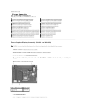
... Dell™ Latitude™ E6400 and E6400 ATG and Mobile Workstation Precision™ M2400 Service Manual Removing the Display Assembly (E6400 and M2400) Replacing the Display Assembly (E6400 and M2400) Removing the Display Assembly (E6400 ATG) Replacing the Display Assembly (E6400 ATG) Removing the Display Bezel (E6400 ...Latch Hook Assembly Replacing the Latch Hook Assembly Removing the Display Cover Replacing the Display Cover Removing the Display Assembly (E6400 and M2400) CAUTION: Before you begin the following procedure, follow the safety instructions that shipped with your computer. ...
... Dell™ Latitude™ E6400 and E6400 ATG and Mobile Workstation Precision™ M2400 Service Manual Removing the Display Assembly (E6400 and M2400) Replacing the Display Assembly (E6400 and M2400) Removing the Display Assembly (E6400 ATG) Replacing the Display Assembly (E6400 ATG) Removing the Display Bezel (E6400 ...Latch Hook Assembly Replacing the Latch Hook Assembly Removing the Display Cover Replacing the Display Cover Removing the Display Assembly (E6400 and M2400) CAUTION: Before you begin the following procedure, follow the safety instructions that shipped with your computer. ...
Service Manual
Page 27
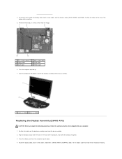
...see Removing the Bottom of the base assembly. 5. Remove the hinge covers (see Replacing the Hinge Covers). 9. Close the display and turn the computer upside down. 4. For WPAN, see Replacing the WLAN/WiMax Card. Follow the instructions in After Working on Your Computer. ...M2.5 x 5-mm screws on the display assembly away from the base assembly. 2. 1 display assembly 2 base assembly Replacing the Display Assembly (E6400 and M2400) CAUTION: Before you begin the following procedure, follow the safety instructions that shipped with your computer. 1. Align the display hinges with ...
...see Removing the Bottom of the base assembly. 5. Remove the hinge covers (see Replacing the Hinge Covers). 9. Close the display and turn the computer upside down. 4. For WPAN, see Replacing the WLAN/WiMax Card. Follow the instructions in After Working on Your Computer. ...M2.5 x 5-mm screws on the display assembly away from the base assembly. 2. 1 display assembly 2 base assembly Replacing the Display Assembly (E6400 and M2400) CAUTION: Before you begin the following procedure, follow the safety instructions that shipped with your computer. 1. Align the display hinges with ...
Service Manual
Page 28
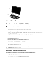
...to 90 degrees and lift the display assembly off the base assembly. 1 display assembly 2 base assembly Replacing the Display Assembly (E6400 ATG) CAUTION: Before you begin the following procedure, follow the safety instructions that shipped with the holes in their respective routing Open... the display to the rear of the computer, and lower the display into place. 3. Turn the computer topside up. 7. 4. Align the display hinges with your computer. 1. Position the cables on the display assembly away from the hinges....
...to 90 degrees and lift the display assembly off the base assembly. 1 display assembly 2 base assembly Replacing the Display Assembly (E6400 ATG) CAUTION: Before you begin the following procedure, follow the safety instructions that shipped with the holes in their respective routing Open... the display to the rear of the computer, and lower the display into place. 3. Turn the computer topside up. 7. 4. Align the display hinges with your computer. 1. Position the cables on the display assembly away from the hinges....
Service Manual
Page 51
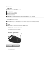
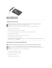
... computer is hot. Close the display and turn off your computer. Remove the M3 x 3-mm screw on Your Computer. 2. NOTICE: Hard drives are extremely fragile. Back to Contents Page Hard Drive Dell™ Latitude™ E6400 and E6400 ATG and Mobile Workstation Precision™ M2400 ...Service Manual Removing the Hard Drive Replacing the Hard Drive Removing the 1.8" Hard Drive (E6400 ATG) Replacing the 1.8" Hard Drive (E6400 ATG) Removing the Modular Hard Drive...
... computer is hot. Close the display and turn off your computer. Remove the M3 x 3-mm screw on Your Computer. 2. NOTICE: Hard drives are extremely fragile. Back to Contents Page Hard Drive Dell™ Latitude™ E6400 and E6400 ATG and Mobile Workstation Precision™ M2400 ...Service Manual Removing the Hard Drive Replacing the Hard Drive Removing the 1.8" Hard Drive (E6400 ATG) Replacing the 1.8" Hard Drive (E6400 ATG) Removing the Modular Hard Drive...
Service Manual
Page 52
...of the procedures in this section, follow the safety instructions that shipped with your computer or at support.dell.com. 1 hard drive bezel 2 pin on bezel bracket 3 hard drive 4 M3 x 3-mm ... hard drive. 1. Remove the two M3 x 3-mm screws. 4. NOTICE: To prevent data loss, turn the computer upside down . 2. Do not remove the hard drive while the computer is hot. Place ... on Your Computer. 2. Exercise care when handling the hard drive. Removing the 1.8" Hard Drive (E6400 ATG) CAUTION: Before you remove the hard drive from the computer while the drive is on one...
...of the procedures in this section, follow the safety instructions that shipped with your computer or at support.dell.com. 1 hard drive bezel 2 pin on bezel bracket 3 hard drive 4 M3 x 3-mm ... hard drive. 1. Remove the two M3 x 3-mm screws. 4. NOTICE: To prevent data loss, turn the computer upside down . 2. Do not remove the hard drive while the computer is hot. Place ... on Your Computer. 2. Exercise care when handling the hard drive. Removing the 1.8" Hard Drive (E6400 ATG) CAUTION: Before you remove the hard drive from the computer while the drive is on one...
Service Manual
Page 56
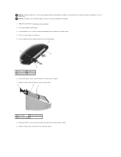
... or in place. 7. Remove the M2.5 x 5-mm screw that holds the carrier for the modular drive, remove the security screw. 4. NOTICE: To prevent data loss, turn off your computer has a security screw for the release latch in to slide the drive out of the hard drive carrier. If your computer before.... 2. Exercise care when handling the hard drive. 1. Slide the release latch carrier out of the modular bay. 1 security screw 2 modular bay 3 modular drive 4 release latch 6. Turn your computer upside down. 3.
... or in place. 7. Remove the M2.5 x 5-mm screw that holds the carrier for the modular drive, remove the security screw. 4. NOTICE: To prevent data loss, turn off your computer has a security screw for the release latch in to slide the drive out of the hard drive carrier. If your computer before.... 2. Exercise care when handling the hard drive. 1. Slide the release latch carrier out of the modular bay. 1 security screw 2 modular bay 3 modular drive 4 release latch 6. Turn your computer upside down. 3.
Service Manual
Page 65
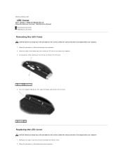
... bay 4. Turn the computer topside up, then open the display and remove the LED cover. 1 LED cover Replacing the LED Cover CAUTION: Before you begin any of the procedures in this section, follow the safety instructions that shipped with your computer. 1. Back to Contents Page LED Cover Dell™ Latitude™ E6400 and E6400 ATG...
... bay 4. Turn the computer topside up, then open the display and remove the LED cover. 1 LED cover Replacing the LED Cover CAUTION: Before you begin any of the procedures in this section, follow the safety instructions that shipped with your computer. 1. Back to Contents Page LED Cover Dell™ Latitude™ E6400 and E6400 ATG...
Service Manual
Page 71
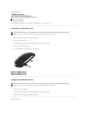
...Back to release it. 5. Push the release latch in this section, follow the safety instructions that shipped with your computer upside down. 3. Turn your computer. Use the release latch to slide the drive out of the modular bay. 1 security screw 2 modular bay 3 modular drive ...your computer has a security screw for the modular drive, replace the security screw. 3. Back to Contents Page Modular Drive Dell™ Latitude™ E6400 and E6400 ATG and Mobile Workstation Precision™ M2400 Service Manual Removing the Modular Drive Replacing the Modular Drive The modular drive supports...
...Back to release it. 5. Push the release latch in this section, follow the safety instructions that shipped with your computer upside down. 3. Turn your computer. Use the release latch to slide the drive out of the modular bay. 1 security screw 2 modular bay 3 modular drive ...your computer has a security screw for the modular drive, replace the security screw. 3. Back to Contents Page Modular Drive Dell™ Latitude™ E6400 and E6400 ATG and Mobile Workstation Precision™ M2400 Service Manual Removing the Modular Drive Replacing the Modular Drive The modular drive supports...


