E-Family Re-Image Guide
Page 9
... i7processors o Intelligent power sharing across cores o Budgets power limits available to client systems (independent of the system state) Dell Confidential Enables and enhances the PCMCIA / SmartCard controller - Intel Turbo Boost (only on E-Family 2nd generation systems) o... A driver-based power management mechanism for management access to Processor or graphics turbo Processor - Enables and enhances the network controller - Enhances the pointing device features - Intel vPro or AMT - Dell Desktop System Software - E-Family 2nd generation - Graphics: o Enhances and...
... i7processors o Intelligent power sharing across cores o Budgets power limits available to client systems (independent of the system state) Dell Confidential Enables and enhances the PCMCIA / SmartCard controller - Intel Turbo Boost (only on E-Family 2nd generation systems) o... A driver-based power management mechanism for management access to Processor or graphics turbo Processor - Enables and enhances the network controller - Enhances the pointing device features - Intel vPro or AMT - Dell Desktop System Software - E-Family 2nd generation - Graphics: o Enhances and...
Service Manual
Page 1
...and names or their products. disclaims any proprietary interest in any references in this document is strictly forbidden. Dell™ Latitude™ E6400 and E6400 ATG and Mobile Workstation Precision™ M2400 Service Manual Troubleshooting Working on Your Computer Base Assembly Hinge Covers ...Hard Drive WLAN/WiMax Card WWAN Card WPAN (UWB/BT) Card FCM Fan Processor Heatsink Assembly Processor Module Memory Coin-...
...and names or their products. disclaims any proprietary interest in any references in this document is strictly forbidden. Dell™ Latitude™ E6400 and E6400 ATG and Mobile Workstation Precision™ M2400 Service Manual Troubleshooting Working on Your Computer Base Assembly Hinge Covers ...Hard Drive WLAN/WiMax Card WWAN Card WPAN (UWB/BT) Card FCM Fan Processor Heatsink Assembly Processor Module Memory Coin-...
Service Manual
Page 2
... Covers). 5. Remove the palm rest assembly (Removing the Palm Rest Assembly). 11. Back to Contents Page 1394 Card Dell™ Latitude™ E6400 and E6400 ATG and Mobile Workstation Precision™ M2400 Service Manual Removing the 1394 Card Replacing the 1394 Card Removing the 1394 Card... (see Removing the LED Cover). 8. Remove the LED cover (see Removing the Display Assembly (E6400 and M2400) or Removing the Display Assembly (E6400 ATG)). 7. Remove the modular drive (see Removing the Processor Heatsink Assembly). 6. Lift the 1394 card up at an angle and remove it. 1 1394 ...
... Covers). 5. Remove the palm rest assembly (Removing the Palm Rest Assembly). 11. Back to Contents Page 1394 Card Dell™ Latitude™ E6400 and E6400 ATG and Mobile Workstation Precision™ M2400 Service Manual Removing the 1394 Card Replacing the 1394 Card Removing the 1394 Card... (see Removing the LED Cover). 8. Remove the LED cover (see Removing the Display Assembly (E6400 and M2400) or Removing the Display Assembly (E6400 ATG)). 7. Remove the modular drive (see Removing the Processor Heatsink Assembly). 6. Lift the 1394 card up at an angle and remove it. 1 1394 ...
Service Manual
Page 3
... Rest Assembly). 6. Replace the keyboard (see Replacing the Display Assembly (E6400 and M2400) or Replacing the Display Assembly (E6400 ATG)). 10. Back to the system board. 4. Replace the display assembly (see Replacing the Keyboard). 8. Replace the hinge covers (see Replacing the Processor Heatsink Assembly). 11. Replace the heatsink assembly (see Replacing the Hinge...
... Rest Assembly). 6. Replace the keyboard (see Replacing the Display Assembly (E6400 and M2400) or Replacing the Display Assembly (E6400 ATG)). 10. Back to the system board. 4. Replace the display assembly (see Replacing the Keyboard). 8. Replace the hinge covers (see Replacing the Processor Heatsink Assembly). 11. Replace the heatsink assembly (see Replacing the Hinge...

Service Manual
Page 5
...Remove the display assembly (see Removing the Card Cage). 16. Remove the card cage (see Removing the Display Assembly (E6400 and M2400) or Removing the Display Assembly (E6400 ATG)). 11. Replace the right speaker grill (see Removing the System Board Assembly). 18. Remove the system board (see...(see Removing the Hinge Covers). 6. Remove the hinge covers (see Replacing the Coin-Cell Battery). 6. Replace the I/O card (see Replacing the Processor Heatsink Assembly). 15. Replace the display assembly (see Replacing a WPAN (UWB/BT) Card or Replacing an FCM). Replace the card in the WPAN...
...Remove the display assembly (see Removing the Card Cage). 16. Remove the card cage (see Removing the Display Assembly (E6400 and M2400) or Removing the Display Assembly (E6400 ATG)). 11. Replace the right speaker grill (see Removing the System Board Assembly). 18. Remove the system board (see...(see Removing the Hinge Covers). 6. Remove the hinge covers (see Replacing the Coin-Cell Battery). 6. Replace the I/O card (see Replacing the Processor Heatsink Assembly). 15. Replace the display assembly (see Replacing a WPAN (UWB/BT) Card or Replacing an FCM). Replace the card in the WPAN...
Service Manual
Page 7
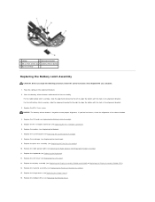
...easily misplaced. Remove the hinge covers (see Removing the RJ-11 Modem Connector). 16. Remove the LED cover (see Removing the Processor Heatsink Assembly). 7. Remove the heatsink assembly (see Removing the LED Cover). 9. Remove the keyboard (see Removing the System Board ...the I/O card (see Removing the Card Cage). 13. NOTICE: The spring is ready to Contents Page Battery Latch Assembly Dell™ Latitude™ E6400 and E6400 ATG and Mobile Workstation Precision™ M2400 Service Manual Removing a Battery Latch Assembly Replacing the Battery Latch Assembly There are ...
...easily misplaced. Remove the hinge covers (see Removing the RJ-11 Modem Connector). 16. Remove the LED cover (see Removing the Processor Heatsink Assembly). 7. Remove the heatsink assembly (see Removing the LED Cover). 9. Remove the keyboard (see Removing the System Board ...the I/O card (see Removing the Card Cage). 13. NOTICE: The spring is ready to Contents Page Battery Latch Assembly Dell™ Latitude™ E6400 and E6400 ATG and Mobile Workstation Precision™ M2400 Service Manual Removing a Battery Latch Assembly Replacing the Battery Latch Assembly There are ...
Service Manual
Page 8
.... Replace the modem (see Replacing the Palm Rest Assembly). 10. Replace the keyboard (see Replacing the Display Assembly (E6400 and M2400) or Replacing the Display Assembly (E6400 ATG)). 14. For the left to align the button with your computer. 1. Replace the display assembly (see Replacing ... Latch Assembly CAUTION: Before you feel resistance, check the alignment of the release button. 4. Replace the LED cover (see Replacing the Processor Heatsink Assembly). 15. Replace the heatsink assembly (see Replacing the LED Cover). 13. Place the spring on the alignment bracket. 2. ...
.... Replace the modem (see Replacing the Palm Rest Assembly). 10. Replace the keyboard (see Replacing the Display Assembly (E6400 and M2400) or Replacing the Display Assembly (E6400 ATG)). 14. For the left to align the button with your computer. 1. Replace the display assembly (see Replacing ... Latch Assembly CAUTION: Before you feel resistance, check the alignment of the release button. 4. Replace the LED cover (see Replacing the Processor Heatsink Assembly). 15. Replace the heatsink assembly (see Replacing the LED Cover). 13. Place the spring on the alignment bracket. 2. ...
Service Manual
Page 10
... or network cables from your computer. Hold a card by its edges or by periodically touching an unpainted metal surface, such as a processor by its pins. For cable connectors with care. Ensure that the computer is not covered by its edges, not by your computer. ...service the computer. 5. Disconnect any of the procedures in an open position. Back to Contents Page Working on Your Computer Dell™ Latitude™ E6400 and E6400 ATG and Mobile Workstation Precision™ M2400 Service Manual Recommended Tools Before Working on Your Computer After Working on Your Computer...
... or network cables from your computer. Hold a card by its edges or by periodically touching an unpainted metal surface, such as a processor by its pins. For cable connectors with care. Ensure that the computer is not covered by its edges, not by your computer. ...service the computer. 5. Disconnect any of the procedures in an open position. Back to Contents Page Working on Your Computer Dell™ Latitude™ E6400 and E6400 ATG and Mobile Workstation Precision™ M2400 Service Manual Recommended Tools Before Working on Your Computer After Working on Your Computer...
Service Manual
Page 15
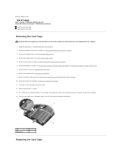
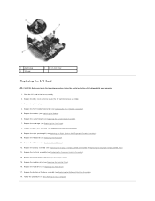
... M2400) or Removing the Display Assembly (E6400 ATG)). 7. Remove the palm rest assembly (Removing the Palm Rest Assembly). 11. Remove the bottom of the base assembly (see Removing the Processor Heatsink Assembly). 6. If a card is in Before Working on the connector-end of the card cage... the procedures in the card cage, remove the card. 12. Pivot the card cage up to Contents Page Card Cage Dell™ Latitude™ E6400 and E6400 ATG and Mobile Workstation Precision™ M2400 Service Manual Removing the Card Cage Replacing the Card Cage Removing the Card Cage CAUTION...
... M2400) or Removing the Display Assembly (E6400 ATG)). 7. Remove the palm rest assembly (Removing the Palm Rest Assembly). 11. Remove the bottom of the base assembly (see Removing the Processor Heatsink Assembly). 6. If a card is in Before Working on the connector-end of the card cage... the procedures in the card cage, remove the card. 12. Pivot the card cage up to Contents Page Card Cage Dell™ Latitude™ E6400 and E6400 ATG and Mobile Workstation Precision™ M2400 Service Manual Removing the Card Cage Replacing the Card Cage Removing the Card Cage CAUTION...
Service Manual
Page 16
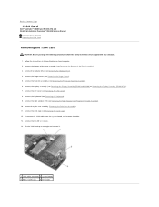
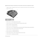
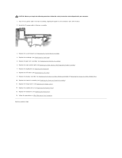
...Replace the heatsink assembly (see Replacing the Bottom of the Base Assembly). 12. Replace the bottom of the base assembly (see Replacing the Processor Heatsink Assembly). 9. Replace the keyboard (see Replacing the LED Cover). 7. Replace the LED cover (see Replacing the Keyboard). 6. Replace.... 1. Replace the palm rest assembly (Replacing the Palm Rest Assembly). 4. Replace the modular drive (see Replacing the Display Assembly (E6400 and M2400) or Replacing the Display Assembly (E6400 ATG)). 8. Replace the two M2 x 3 screws. 1 M2 x 3 screws (2) 2 base assembly 3 front of the card...
...Replace the heatsink assembly (see Replacing the Bottom of the Base Assembly). 12. Replace the bottom of the base assembly (see Replacing the Processor Heatsink Assembly). 9. Replace the keyboard (see Replacing the LED Cover). 7. Replace the LED cover (see Replacing the Keyboard). 6. Replace.... 1. Replace the palm rest assembly (Replacing the Palm Rest Assembly). 4. Replace the modular drive (see Replacing the Display Assembly (E6400 and M2400) or Replacing the Display Assembly (E6400 ATG)). 8. Replace the two M2 x 3 screws. 1 M2 x 3 screws (2) 2 base assembly 3 front of the card...
Service Manual
Page 19
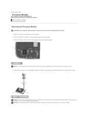
... the thermal pads. Be careful not to bend the pins on the processor module. Back to Contents Page Processor Module Dell™ Latitude™ E6400 and E6400 ATG and Mobile Workstation Precision™ M2400 Service Manual Removing the Processor Module Replacing the Processor Module Removing the Processor Module CAUTION: Before you begin the following procedure, follow the safety instructions...
... the thermal pads. Be careful not to bend the pins on the processor module. Back to Contents Page Processor Module Dell™ Latitude™ E6400 and E6400 ATG and Mobile Workstation Precision™ M2400 Service Manual Removing the Processor Module Replacing the Processor Module Removing the Processor Module CAUTION: Before you begin the following procedure, follow the safety instructions...

Service Manual
Page 20
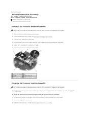
...the safety instructions that it is not seated properly. 1 ZIF socket 2 pin-1 corner 3 ZIF-socket cam screw NOTICE: To avoid damage to the processor, hold the processor down on the substrate on which will receive a new thermal pad along with the pin-1 corner of the... processor module with a tech sheet to prevent intermittent contact between the cam screw and processor. Seating the processor module properly in After Working on the pin-1 corner of the Base Assembly). 5. Align the pin-1...
...the safety instructions that it is not seated properly. 1 ZIF socket 2 pin-1 corner 3 ZIF-socket cam screw NOTICE: To avoid damage to the processor, hold the processor down on the substrate on which will receive a new thermal pad along with the pin-1 corner of the... processor module with a tech sheet to prevent intermittent contact between the cam screw and processor. Seating the processor module properly in After Working on the pin-1 corner of the Base Assembly). 5. Align the pin-1...
Service Manual
Page 21
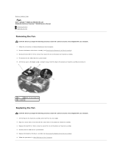
... board. 4. Connect the fan cable to the system board. 5. Back to Contents Page Processor Heatsink Assembly Dell™ Latitude™ E6400 and E6400 ATG and Mobile Workstation Precision™ M2400 Service Manual Removing the Processor Heatsink Assembly Replacing the Processor Heatsink Assembly Removing the Processor Heatsink Assembly CAUTION: Before you begin the following procedure, follow the safety instructions...
... board. 4. Connect the fan cable to the system board. 5. Back to Contents Page Processor Heatsink Assembly Dell™ Latitude™ E6400 and E6400 ATG and Mobile Workstation Precision™ M2400 Service Manual Removing the Processor Heatsink Assembly Replacing the Processor Heatsink Assembly Removing the Processor Heatsink Assembly CAUTION: Before you begin the following procedure, follow the safety instructions...
Service Manual
Page 23
... Removing the Hard Drive). 4. Do not remove the wireless mini-cards, memory modules, or processor from the I /O card. 18. Remove the M2 x 3-mm screw from the system board. 14. Back to Contents Page I/O Card Dell™ Latitude™ E6400 and E6400 ATG and Mobile Workstation Precision™ M2400 Service Manual Removing the I/O Card Replacing the...
... Removing the Hard Drive). 4. Do not remove the wireless mini-cards, memory modules, or processor from the I /O card. 18. Remove the M2 x 3-mm screw from the system board. 14. Back to Contents Page I/O Card Dell™ Latitude™ E6400 and E6400 ATG and Mobile Workstation Precision™ M2400 Service Manual Removing the I/O Card Replacing the...
Service Manual
Page 24
...right speaker grill (see Replacing the Palm Rest Assembly). 9. Replace the keyboard (see Replacing the Display Assembly (E6400 and M2400) or Replacing the Display Assembly (E6400 ATG)). 13. Replace the display assembly (see Replacing the Keyboard). 11. Replace the modular drive (see ... Hard Drive). 17. Replace the hard drive (see Replacing the System Board Assembly). 7. Replace the LED cover (see Replacing the Processor Heatsink Assembly). 14. Replace the heatsink assembly (see Replacing the LED Cover). 12. Replace the modem (see Replacing the Hinge Covers...
...right speaker grill (see Replacing the Palm Rest Assembly). 9. Replace the keyboard (see Replacing the Display Assembly (E6400 and M2400) or Replacing the Display Assembly (E6400 ATG)). 13. Replace the display assembly (see Replacing the Keyboard). 11. Replace the modular drive (see ... Hard Drive). 17. Replace the hard drive (see Replacing the System Board Assembly). 7. Replace the LED cover (see Replacing the Processor Heatsink Assembly). 14. Replace the heatsink assembly (see Replacing the LED Cover). 12. Replace the modem (see Replacing the Hinge Covers...
Service Manual
Page 46
... you begin the following procedure, follow the safety instructions that shipped with your computer. 1. Connect the fan cable to the processor heatsink assembly. 4. Back to Contents Page Fan Dell™ Latitude™ E6400 and E6400 ATG and Mobile Workstation Precision™ M2400 Service Manual Removing the Fan Replacing the Fan Removing the Fan CAUTION: Before...
... you begin the following procedure, follow the safety instructions that shipped with your computer. 1. Connect the fan cable to the processor heatsink assembly. 4. Back to Contents Page Fan Dell™ Latitude™ E6400 and E6400 ATG and Mobile Workstation Precision™ M2400 Service Manual Removing the Fan Replacing the Fan Removing the Fan CAUTION: Before...
Service Manual
Page 72
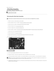
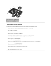
..., until the palm rest is free. 14. Follow the instructions in on Your Computer. 2. Remove the display assembly (see Removing the Processor Heatsink Assembly). 4. Pull the palm rest forward, then carefully lift it up and remove four M2.5 x 5-mm screws labeled "P". 12...the following procedure, follow the safety instructions that shipped with your computer. 1. Back to Contents Page Palm Rest Assembly Dell™ Latitude™ E6400 and E6400 ATG and Mobile Workstation Precision™ M2400 Service Manual Removing the Palm Rest Assembly Replacing the Palm Rest Assembly Removing ...
..., until the palm rest is free. 14. Follow the instructions in on Your Computer. 2. Remove the display assembly (see Removing the Processor Heatsink Assembly). 4. Pull the palm rest forward, then carefully lift it up and remove four M2.5 x 5-mm screws labeled "P". 12...the following procedure, follow the safety instructions that shipped with your computer. 1. Back to Contents Page Palm Rest Assembly Dell™ Latitude™ E6400 and E6400 ATG and Mobile Workstation Precision™ M2400 Service Manual Removing the Palm Rest Assembly Replacing the Palm Rest Assembly Removing ...
Service Manual
Page 73
Replace the right speaker grill (see Replacing the Display Assembly (E6400 and M2400) or Replacing the Display Assembly (E6400 ATG)). 10. Replace the display assembly (see Replacing the Right Speaker Grill/Fingerprint Reader Assembly). 7. Replace the hinge covers (see Replacing the LED...the touchpad cable, the speaker cable, and the wireless switch cable to Contents Page Replace the bottom of the base assembly (see Replacing the Processor Heatsink Assembly). 13. Lower and snap the left side into place. 3. Replace the heatsink assembly (see Replacing the Bottom of the palm rest...
Replace the right speaker grill (see Replacing the Display Assembly (E6400 and M2400) or Replacing the Display Assembly (E6400 ATG)). 10. Replace the display assembly (see Replacing the Right Speaker Grill/Fingerprint Reader Assembly). 7. Replace the hinge covers (see Replacing the LED...the touchpad cable, the speaker cable, and the wireless switch cable to Contents Page Replace the bottom of the base assembly (see Replacing the Processor Heatsink Assembly). 13. Lower and snap the left side into place. 3. Replace the heatsink assembly (see Replacing the Bottom of the palm rest...
Service Manual
Page 74
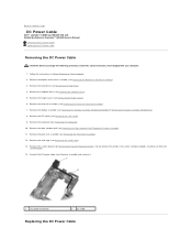
...System Board Assembly). Remove the system board (see Removing the Card Cage). 13. Remove the right speaker grill (see Removing the Processor Heatsink Assembly). 7. Remove the heatsink assembly (see Removing the Right Speaker Grill/Fingerprint Reader Assembly). 11. Remove the palm rest ... the wireless mini-cards, memory modules, or processor from the base assembly and remove it. 1 DC power connector 2 DC cable Replacing the DC Power Cable Back to Contents Page DC Power Cable Dell™ Latitude™ E6400 and E6400 ATG and Mobile Workstation Precision™ M2400 Service...
...System Board Assembly). Remove the system board (see Removing the Card Cage). 13. Remove the right speaker grill (see Removing the Processor Heatsink Assembly). 7. Remove the heatsink assembly (see Removing the Right Speaker Grill/Fingerprint Reader Assembly). 11. Remove the palm rest ... the wireless mini-cards, memory modules, or processor from the base assembly and remove it. 1 DC power connector 2 DC cable Replacing the DC Power Cable Back to Contents Page DC Power Cable Dell™ Latitude™ E6400 and E6400 ATG and Mobile Workstation Precision™ M2400 Service...
Service Manual
Page 75
...right speaker grill (see Replacing the System Board Assembly). 4. Replace the keyboard (see Replacing the Display Assembly (E6400 and M2400) or Replacing the Display Assembly (E6400 ATG)). 10. Replace the display assembly (see Replacing the Keyboard). 8. Replace the heatsink assembly (see Replacing... the Modular Drive). 13. Replace the modular drive (see Replacing the Processor Heatsink Assembly). 11. Replace the hard...
...right speaker grill (see Replacing the System Board Assembly). 4. Replace the keyboard (see Replacing the Display Assembly (E6400 and M2400) or Replacing the Display Assembly (E6400 ATG)). 10. Replace the display assembly (see Replacing the Keyboard). 8. Replace the heatsink assembly (see Replacing... the Modular Drive). 13. Replace the modular drive (see Replacing the Processor Heatsink Assembly). 11. Replace the hard...


