Service Manual
Page 28
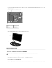
... turn the computer upside down. 4. Route the display cable, touch screen cable, and wireless (WLAN, WWAN, and WPAN) cables. Position all cables to 90 degrees and lift the display assembly off the base assembly. 1 display assembly 2 base assembly Replacing the Display Assembly (E6400 ATG) CAUTION: Before you begin the following procedure, follow the safety... in the base of the laptop after unrouting. 5. 4. Remove the two M2.5 x 5-mm screws from the base assembly. 2. Disconnect and unroute the display cable, touch screen cable, and the wireless cables (WLAN, WWAN, and WPAN).
... turn the computer upside down. 4. Route the display cable, touch screen cable, and wireless (WLAN, WWAN, and WPAN) cables. Position all cables to 90 degrees and lift the display assembly off the base assembly. 1 display assembly 2 base assembly Replacing the Display Assembly (E6400 ATG) CAUTION: Before you begin the following procedure, follow the safety... in the base of the laptop after unrouting. 5. 4. Remove the two M2.5 x 5-mm screws from the base assembly. 2. Disconnect and unroute the display cable, touch screen cable, and the wireless cables (WLAN, WWAN, and WPAN).
Service Manual
Page 36
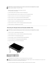
... covers (see Removing the Display Bezel (E6400 ATG)). 6. Remove the display bezel (see Removing the Hinge Covers). 4. Remove the four M2.5 x 5-mm screws from the display panel. 1 M2.5 x 5-mm screws (4) 2 display panel 3 display cover 7. Replace the four M2.5 x 5-mm screws that shipped with your computer. 1. NOTICE: Touch screen display panels include a second cable (touch...
... covers (see Removing the Display Bezel (E6400 ATG)). 6. Remove the display bezel (see Removing the Hinge Covers). 4. Remove the four M2.5 x 5-mm screws from the display panel. 1 M2.5 x 5-mm screws (4) 2 display panel 3 display cover 7. Replace the four M2.5 x 5-mm screws that shipped with your computer. 1. NOTICE: Touch screen display panels include a second cable (touch...
Service Manual
Page 37
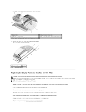
... the display cable to the connector on the left ) and "R" (right). 1. Replace the four M2.5 x 5-mm screws that secure the display panel to align each bracket. 6. Replace the display bezel (see Replacing the Display Bezel (E6400 ATG)). 9. For touch screen display panels, disconnect the touch screen cable. 1 display cable 2 display connector release tabs 3 underside of the display...
... the display cable to the connector on the left ) and "R" (right). 1. Replace the four M2.5 x 5-mm screws that secure the display panel to align each bracket. 6. Replace the display bezel (see Replacing the Display Bezel (E6400 ATG)). 9. For touch screen display panels, disconnect the touch screen cable. 1 display cable 2 display connector release tabs 3 underside of the display...


