
User Manual
Page 2
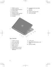
USB 3.0 connector 8. wireless switch 10. fingerprint reader (optional) 12. keyboard 16. network connector 2. device status lights 3. VGA connector 6. Secure Digital (SD) memory-card reader 10. touchpad 14. volume control buttons (3) 17. Back View 1. audio/microphone combo connector 8. cooling vents 9. device status lights Figure 2. security cable slot 4. eSATA/USB 2.0 connector 7. ExpressCard slot 11. contactless smart-card reader (optional) 15. power connector 5. 7. touchpad buttons (2) 13. smart card reader 2 powered USB 3.0 connector 9.
USB 3.0 connector 8. wireless switch 10. fingerprint reader (optional) 12. keyboard 16. network connector 2. device status lights 3. VGA connector 6. Secure Digital (SD) memory-card reader 10. touchpad 14. volume control buttons (3) 17. Back View 1. audio/microphone combo connector 8. cooling vents 9. device status lights Figure 2. security cable slot 4. eSATA/USB 2.0 connector 7. ExpressCard slot 11. contactless smart-card reader (optional) 15. power connector 5. 7. touchpad buttons (2) 13. smart card reader 2 powered USB 3.0 connector 9.
User Manual
Page 4
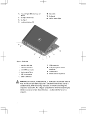
.... device status lights 5. The computer turns on the fan when the computer gets hot. Fan noise is running. touchpad buttons (2) 16. keyboard 20. Do not store your Dell computer in the air vents. 14. touchpad 17. device status lights Figure 4. Back view 1. network connector 3. USB 3.0 connector 6. cooling vents 10. Restricting the airflow can...
.... device status lights 5. The computer turns on the fan when the computer gets hot. Fan noise is running. touchpad buttons (2) 16. keyboard 20. Do not store your Dell computer in the air vents. 14. touchpad 17. device status lights Figure 4. Back view 1. network connector 3. USB 3.0 connector 6. cooling vents 10. Restricting the airflow can...
Owner's Manual
Page 19
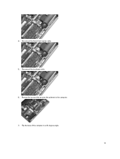
4. Remove the screws that secures the palmrest to a 45-degree angle. 19 Disconnect the Smart Card reader cable. 5. Flip the base of the computer to the computer. 7. Disconnect the touchpad cable. 6.
4. Remove the screws that secures the palmrest to a 45-degree angle. 19 Disconnect the Smart Card reader cable. 5. Flip the base of the computer to the computer. 7. Disconnect the touchpad cable. 6.
Owner's Manual
Page 20
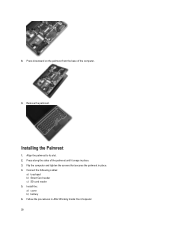
Align the palmrest to its slot. 2. Install the: a) cover b) battery 6. Press along the sides of the computer. 9. Follow the procedures in place. 3. Flip the computer and tighten the screws that secures the palmrest in place. 4. 8. Installing the Palmrest 1. Connect the following cables: a) touchpad b) Smart Card reader c) SD card reader 5. Remove the palmrest. Press downward on the palmrest from the base of the palmrest until it snaps in After Working Inside Your Computer. 20
Align the palmrest to its slot. 2. Install the: a) cover b) battery 6. Press along the sides of the computer. 9. Follow the procedures in place. 3. Flip the computer and tighten the screws that secures the palmrest in place. 4. 8. Installing the Palmrest 1. Connect the following cables: a) touchpad b) Smart Card reader c) SD card reader 5. Remove the palmrest. Press downward on the palmrest from the base of the palmrest until it snaps in After Working Inside Your Computer. 20

Owner's Manual
Page 28
Installing the Speakers 1. Disconnect the hall sensor cable. 28 Disconnect the touchpad cable. 4. Follow the procedures in After Working Inside Your Computer. Tighten the screws to secure both the speakers 3. Install the: a) base cover b) battery c) ExpressCard d) SD ...
Installing the Speakers 1. Disconnect the hall sensor cable. 28 Disconnect the touchpad cable. 4. Follow the procedures in After Working Inside Your Computer. Tighten the screws to secure both the speakers 3. Install the: a) base cover b) battery c) ExpressCard d) SD ...
Owner's Manual
Page 29
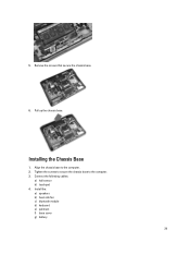
Installing the Chassis Base 1. 5. Align the chassis base to the computer. 3. Connect the following cables: a) hall sensor b) touchpad 4. Tighten the screws to secure the chassis base to the computer. 2. Install the: a) speakers b) heat-sink fan c) bluetooth module d) keyboard e) palmrest f) base cover g) battery 29 Pull up the chassis base. Remove the screws that secure the chassis base. 6.
Installing the Chassis Base 1. 5. Align the chassis base to the computer. 3. Connect the following cables: a) hall sensor b) touchpad 4. Tighten the screws to secure the chassis base to the computer. 2. Install the: a) speakers b) heat-sink fan c) bluetooth module d) keyboard e) palmrest f) base cover g) battery 29 Pull up the chassis base. Remove the screws that secure the chassis base. 6.
Owner's Manual
Page 58
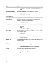
...option is enabled by default. Allows you can be enabled when the computer boots. you to define how the computer handles the mouse and touchpad input. The options are used. This option is enabled by default. • Enable Keyboard Error Detection Specifies whether the sign-on screen... Warnings Allows you to activate the adapter warning messages when certain power adapters are : • Serial Mouse • PS2 Mouse • Touchpad/PS-2 Mouse (Default Setting) Specifies if the NumLock function can set the percentage to match the key feature of PS-2 keyboard with the key...
...option is enabled by default. Allows you can be enabled when the computer boots. you to define how the computer handles the mouse and touchpad input. The options are used. This option is enabled by default. • Enable Keyboard Error Detection Specifies whether the sign-on screen... Warnings Allows you to activate the adapter warning messages when certain power adapters are : • Serial Mouse • PS2 Mouse • Touchpad/PS-2 Mouse (Default Setting) Specifies if the NumLock function can set the percentage to match the key feature of PS-2 keyboard with the key...
Owner's Manual
Page 69
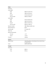
Display Dimensions: Latitude E6230 Height Width Diagonal Active area (X/Y) Latitude E6330 Height Width Diagonal Active area (X/Y) Maximum resolution Maximum Brightness Operating angle Refresh rate Minimum Viewing angles: Horizontal Vertical Pixel pitch Keyboard Number of keys Layout Touchpad Active Area: X-axis Y-axis 300.90 mm (11.84 inches) 180.00 mm (7.08 inches) 317.30 mm...
Display Dimensions: Latitude E6230 Height Width Diagonal Active area (X/Y) Latitude E6330 Height Width Diagonal Active area (X/Y) Maximum resolution Maximum Brightness Operating angle Refresh rate Minimum Viewing angles: Horizontal Vertical Pixel pitch Keyboard Number of keys Layout Touchpad Active Area: X-axis Y-axis 300.90 mm (11.84 inches) 180.00 mm (7.08 inches) 317.30 mm...


