
Dell Latitude E5440/E5540 Setup And Features Information
Page 2
volume-up button Figure 2. USB 2.0 connector 3. wireless switch 5. cooling vents 6. USB 3.0 connector 8. Base View 1. docking connector 2 4. trackstick (optional) 23. SD card slot 9. SIM card slot (optional) 5. mute button 25. network connector 2. 21. battery latch 2. battery bay 3. keyboard 24. ExpressCard or Smart Card slot (optional) Figure 3. Back View 1. trackstick buttons (3) (optional) 22. volume-down button 26. HDMI connector 7. battery latch power connector 4.
volume-up button Figure 2. USB 2.0 connector 3. wireless switch 5. cooling vents 6. USB 3.0 connector 8. Base View 1. docking connector 2 4. trackstick (optional) 23. SD card slot 9. SIM card slot (optional) 5. mute button 25. network connector 2. 21. battery latch 2. battery bay 3. keyboard 24. ExpressCard or Smart Card slot (optional) Figure 3. Back View 1. trackstick buttons (3) (optional) 22. volume-down button 26. HDMI connector 7. battery latch power connector 4.
Dell Latitude E5440/E5540 Setup And Features Information
Page 3
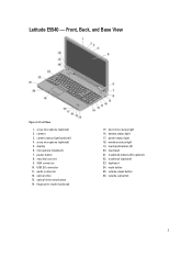
... button 25. Front View 1. camera 3. VGA connector 10. optical drive 13. touchpad buttons (2) 20. keyboard 24. power button 8. optical-drive eject button 14. touchpad 21. volume-down button 26. wireless status light 19. display 6. security lock slot 9. Latitude E5540 - Front, Back, and Base View Figure 4. camera status light (optional) 4. microphone (standard) 7. audio connector...
... button 25. Front View 1. camera 3. VGA connector 10. optical drive 13. touchpad buttons (2) 20. keyboard 24. power button 8. optical-drive eject button 14. touchpad 21. volume-down button 26. wireless status light 19. display 6. security lock slot 9. Latitude E5540 - Front, Back, and Base View Figure 4. camera status light (optional) 4. microphone (standard) 7. audio connector...
Dell Latitude E5440/E5540 Setup And Features Information
Page 5
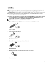
For additional best practices information, see www.dell.com/regulatory_compliance WARNING: The AC adapter works with your computer. Connect the AC adapter to the AC adapter connector on the computer. USB Connector 4. Open ... order them. 1. NOTE: Some devices may cause fire or equipment damage. AC Adapter 2. Connect the network cable (optional). Connect USB devices, such as a mouse or keyboard (optional).
For additional best practices information, see www.dell.com/regulatory_compliance WARNING: The AC adapter works with your computer. Connect the AC adapter to the AC adapter connector on the computer. USB Connector 4. Open ... order them. 1. NOTE: Some devices may cause fire or equipment damage. AC Adapter 2. Connect the network cable (optional). Connect USB devices, such as a mouse or keyboard (optional).

Dell Owners Manual
Page 3
... Removing the Display Panel...13 Installing the Display Panel...14 Removing the Camera...14 Installing the Camera...15 Removing the Keyboard Trim...15 Installing the Keyboard Trim...15 Removing the Keyboard...15 Installing the Keyboard...16 Removing the Base Cover...17 Installing the Base Cover...17 Removing the Memory Module...17 Installing the Memory...
... Removing the Display Panel...13 Installing the Display Panel...14 Removing the Camera...14 Installing the Camera...15 Removing the Keyboard Trim...15 Installing the Keyboard Trim...15 Removing the Keyboard...15 Installing the Keyboard...16 Removing the Base Cover...17 Installing the Base Cover...17 Removing the Memory Module...17 Installing the Memory...

Dell Owners Manual
Page 15
...Remove: a) battery 15 Tighten the screw to its sides and the top edge. b) Pry up the keyboard trim on its place. 2. Press along the sides of the computer to secure the keyboard trim. 4. Follow the procedures in After Working Inside Your Computer. Remove the battery. 3. Follow the procedures... secure the camera and microphone module. 4. Place the camera and microphone module on its place. 2. c) Lift upwards and remove the keyboard trim from the computer. Tighten the screw at the back of the computer. Installing the Camera 1. Follow the procedures in Before Working ...
...Remove: a) battery 15 Tighten the screw to its sides and the top edge. b) Pry up the keyboard trim on its place. 2. Press along the sides of the computer to secure the keyboard trim. 4. Follow the procedures in After Working Inside Your Computer. Remove the battery. 3. Follow the procedures... secure the camera and microphone module. 4. Place the camera and microphone module on its place. 2. c) Lift upwards and remove the keyboard trim from the computer. Tighten the screw at the back of the computer. Installing the Camera 1. Follow the procedures in Before Working ...

Dell Owners Manual
Page 16
... screws at the back of the computer and flip the computer over [1] and [2] b) Disconnect the keyboard cable [1] and [2] and lift the keyboard to the computer. 4. Place the keyboard into its place until all the snaps are fully engaged with the computer. 4. Install the screws to... secure the keyboard to the keyboard. 2. Connect the keyboard cable to the palmrest. 5. Install: a) keyboard trim b) battery 7. Follow the procedures in After Working Inside Your Computer. 16 Installing the Keyboard 1. b) Remove the screws that all the metal tabs...
... screws at the back of the computer and flip the computer over [1] and [2] b) Disconnect the keyboard cable [1] and [2] and lift the keyboard to the computer. 4. Place the keyboard into its place until all the snaps are fully engaged with the computer. 4. Install the screws to... secure the keyboard to the keyboard. 2. Connect the keyboard cable to the palmrest. 5. Install: a) keyboard trim b) battery 7. Follow the procedures in After Working Inside Your Computer. 16 Installing the Keyboard 1. b) Remove the screws that all the metal tabs...

Dell Owners Manual
Page 22
Installing the Coin-Cell Battery 1. Remove: a) battery b) base cover c) keyboard trim d) keyboard 3. b) Lift and remove the display hinge from the adhesive. a) battery b) base cover 3. Follow the procedures in Before Working Inside Your Computer. 2. Perform the following steps: a) ...
Installing the Coin-Cell Battery 1. Remove: a) battery b) base cover c) keyboard trim d) keyboard 3. b) Lift and remove the display hinge from the adhesive. a) battery b) base cover 3. Follow the procedures in Before Working Inside Your Computer. 2. Perform the following steps: a) ...

Dell Owners Manual
Page 23
... and back of the computer and disconnect: a) power-connector cable [1] and [2] b) media-buttons cable [1] and [2] c) touch-pad cable [1] and [2] d) fingerprint-scanner cable [1] and [2] 23 Install: a) keyboard b) keyboard trim c) base cover d) battery 4. Removing the Palmrest 1. Place the display hinge on the computer. 2. Remove: a) SD card b) battery c) base cover...
... and back of the computer and disconnect: a) power-connector cable [1] and [2] b) media-buttons cable [1] and [2] c) touch-pad cable [1] and [2] d) fingerprint-scanner cable [1] and [2] 23 Install: a) keyboard b) keyboard trim c) base cover d) battery 4. Removing the Palmrest 1. Place the display hinge on the computer. 2. Remove: a) SD card b) battery c) base cover...
Dell Owners Manual
Page 24
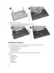
... system board: a) power-button cable b) fingerprint-scanner cable c) touch-pad cable d) media button cable 3. Install: a) display hinge b) hard-drive cage c) hard drive d) optical drive e) memory f) keyboard g) keyboard trim 24 Installing the Palmrest 1. Align the palmrest assembly to secure the palmrest at the front and back of the computer. 4. Tighten the screws to...
... system board: a) power-button cable b) fingerprint-scanner cable c) touch-pad cable d) media button cable 3. Install: a) display hinge b) hard-drive cage c) hard drive d) optical drive e) memory f) keyboard g) keyboard trim 24 Installing the Palmrest 1. Align the palmrest assembly to secure the palmrest at the front and back of the computer. 4. Tighten the screws to...

Dell Owners Manual
Page 25
... computer and snap it into place. 2. Install the screws that secure the ExpressCard cage. Install: a) palmrest b) display hinge c) keyboard d) keyboard trim e) base cover 25 Removing the ExpressCard Cage 1. Remove: a) SD card b) battery c) base cover d) keyboard trim e) keyboard f) display hinge g) palmrest 3. b) Lift and remove the ExpressCard cage from the computer. Installing the ExpressCard Cage 1. Follow...
... computer and snap it into place. 2. Install the screws that secure the ExpressCard cage. Install: a) palmrest b) display hinge c) keyboard d) keyboard trim e) base cover 25 Removing the ExpressCard Cage 1. Remove: a) SD card b) battery c) base cover d) keyboard trim e) keyboard f) display hinge g) palmrest 3. b) Lift and remove the ExpressCard cage from the computer. Installing the ExpressCard Cage 1. Follow...

Dell Owners Manual
Page 26
Remove: a) SD card b) battery c) base cover d) keyboard trim e) keyboard f) memory g) optical drive h) hard drive i) hard-drive cage j) display hinge k) palmrest 3. f) battery g) SD card 4. Follow the procedures in After Working Inside Your Computer. Installing the ...
Remove: a) SD card b) battery c) base cover d) keyboard trim e) keyboard f) memory g) optical drive h) hard drive i) hard-drive cage j) display hinge k) palmrest 3. f) battery g) SD card 4. Follow the procedures in After Working Inside Your Computer. Installing the ...

Dell Owners Manual
Page 27
Removing the System Board 1. Disconnect: a) coin-cell battery cable b) power-connector cable c) speaker cable 27 Follow the procedures in After Working Inside Your Computer. Follow the procedures in Before Working Inside Your Computer. 2. Remove: a) SD card b) battery c) base cover d) keyboard trim e) keyboard f) memory g) optical drive h) hard drive i) hard-drive cage j) WLAN card k) display hinge l) palmrest m) system fan n) ExpressCard cage 3. f) optical drive g) keyboard h) keyboard trim i) base cover j) battery k) SD card 6.
Removing the System Board 1. Disconnect: a) coin-cell battery cable b) power-connector cable c) speaker cable 27 Follow the procedures in After Working Inside Your Computer. Follow the procedures in Before Working Inside Your Computer. 2. Remove: a) SD card b) battery c) base cover d) keyboard trim e) keyboard f) memory g) optical drive h) hard drive i) hard-drive cage j) WLAN card k) display hinge l) palmrest m) system fan n) ExpressCard cage 3. f) optical drive g) keyboard h) keyboard trim i) base cover j) battery k) SD card 6.

Dell Owners Manual
Page 29
Follow the procedures in After Working Inside Your Computer. Remove: a) SD card b) battery c) base cover d) keyboard trim e) keyboard f) memory g) optical drive h) hard drive i) hard-drive cage j) WLAN card k) display hinge l) palmrest m) system fan n) ExpressCard cage o) system board 3. b) Lift to remove the heatsink from ... screws that secure the heatsink in place. Removing the Heatsink 1. b) system fan c) palmrest d) display hinge e) WLAN card f) hard-drive cage g) hard drive h) optical drive i) memory j) keyboard k) keyboard trim l) base cover m) battery n) SD card 6.
Follow the procedures in After Working Inside Your Computer. Remove: a) SD card b) battery c) base cover d) keyboard trim e) keyboard f) memory g) optical drive h) hard drive i) hard-drive cage j) WLAN card k) display hinge l) palmrest m) system fan n) ExpressCard cage o) system board 3. b) Lift to remove the heatsink from ... screws that secure the heatsink in place. Removing the Heatsink 1. b) system fan c) palmrest d) display hinge e) WLAN card f) hard-drive cage g) hard drive h) optical drive i) memory j) keyboard k) keyboard trim l) base cover m) battery n) SD card 6.

Dell Owners Manual
Page 30
Tighten the screws to secure the heatsink to the computer. 3. Removing the I/O Board (Left) 1. Install: a) system board b) ExpressCard cage c) system fan d) palmrest e) display hinge f) WLAN card g) hard-drive cage h) hard drive i) optical drive j) memory k) keyboard l) keyboard trim m) base cover n) battery o) SD card 4. Installing the Heatsink 1. Follow the procedures in After Working Inside Your Computer. Follow the procedures in Before Working Inside Your Computer. 2. Remove: a) SD card b) battery c) base cover 30 Place the heatsink on the system board. 2.
Tighten the screws to secure the heatsink to the computer. 3. Removing the I/O Board (Left) 1. Install: a) system board b) ExpressCard cage c) system fan d) palmrest e) display hinge f) WLAN card g) hard-drive cage h) hard drive i) optical drive j) memory k) keyboard l) keyboard trim m) base cover n) battery o) SD card 4. Installing the Heatsink 1. Follow the procedures in After Working Inside Your Computer. Follow the procedures in Before Working Inside Your Computer. 2. Remove: a) SD card b) battery c) base cover 30 Place the heatsink on the system board. 2.

Dell Owners Manual
Page 31
d) keyboard trim e) keyboard f) memory g) optical drive h) hard drive i) hard-drive cage j) WLAN card k) display hinge l) palmrest m) system fan n) ExpressCard cage o) system board 3. Perform the following steps: a) Remove the ... computer. Place the I /O Board (Left) 1. Install: a) system board b) ExpressCard cage c) system fan d) palmrest e) display hinge f) WLAN card g) hard-drive cage h) hard drive i) optical drive j) memory k) keyboard l) keyboard trim m) base cover n) battery 31
d) keyboard trim e) keyboard f) memory g) optical drive h) hard drive i) hard-drive cage j) WLAN card k) display hinge l) palmrest m) system fan n) ExpressCard cage o) system board 3. Perform the following steps: a) Remove the ... computer. Place the I /O Board (Left) 1. Install: a) system board b) ExpressCard cage c) system fan d) palmrest e) display hinge f) WLAN card g) hard-drive cage h) hard drive i) optical drive j) memory k) keyboard l) keyboard trim m) base cover n) battery 31

Dell Owners Manual
Page 32
Removing the I /O board to secure the I /O Board (Right) 1. Place the I /O board on the computer. 2. Remove: a) SD card b) battery c) base cover d) keyboard trim e) keyboard f) memory g) optical drive h) hard drive i) hard-drive cage j) WLAN card k) display hinge l) palmrest m) system fan n) ExpressCard cage o) system board 3. Tighten the screws to the computer. 3. b) ...
Removing the I /O board to secure the I /O Board (Right) 1. Place the I /O board on the computer. 2. Remove: a) SD card b) battery c) base cover d) keyboard trim e) keyboard f) memory g) optical drive h) hard drive i) hard-drive cage j) WLAN card k) display hinge l) palmrest m) system fan n) ExpressCard cage o) system board 3. Tighten the screws to the computer. 3. b) ...

Dell Owners Manual
Page 33
Remove: a) SD card b) battery c) base cover d) keyboard trim e) keyboard f) memory g) hard drive h) hard-drive cage i) optical drive j) WLAN card k) display hinge l) palmrest m) ExpressCard cage n) system fan o) system board 3. Perform the following steps: a) Remove the ... Your Computer. b) Lift and remove the power connector from the routing channels. d) palmrest e) display hinge f) WLAN card g) hard drive h) hard-drive cage i) optical drive j) memory k) keyboard l) keyboard trim m) base cover n) battery o) SD card 4. Removing the Power Connector 1.
Remove: a) SD card b) battery c) base cover d) keyboard trim e) keyboard f) memory g) hard drive h) hard-drive cage i) optical drive j) WLAN card k) display hinge l) palmrest m) ExpressCard cage n) system fan o) system board 3. Perform the following steps: a) Remove the ... Your Computer. b) Lift and remove the power connector from the routing channels. d) palmrest e) display hinge f) WLAN card g) hard drive h) hard-drive cage i) optical drive j) memory k) keyboard l) keyboard trim m) base cover n) battery o) SD card 4. Removing the Power Connector 1.

Dell Owners Manual
Page 34
...system fan c) ExpressCard cage d) palmrest e) display hinge f) WLAN card g) hard-drive cage h) hard drive i) optical drive j) memory k) keyboard l) keyboard trim m) base cover n) battery o) SD card 4. Installing the Power Connector 1. Follow the procedures in Before Working Inside Your Computer. 2.... a) Remove the speaker cable from the computer. 34 Removing the Speakers 1. Remove: a) SD memory card b) battery c) base cover d) keyboard trim e) keyboard f) memory g) optical drive h) hard drive i) hard-drive cage j) WLAN card k) display hinge l) palmrest m) system fan n) ExpressCard cage...
...system fan c) ExpressCard cage d) palmrest e) display hinge f) WLAN card g) hard-drive cage h) hard drive i) optical drive j) memory k) keyboard l) keyboard trim m) base cover n) battery o) SD card 4. Installing the Power Connector 1. Follow the procedures in Before Working Inside Your Computer. 2.... a) Remove the speaker cable from the computer. 34 Removing the Speakers 1. Remove: a) SD memory card b) battery c) base cover d) keyboard trim e) keyboard f) memory g) optical drive h) hard drive i) hard-drive cage j) WLAN card k) display hinge l) palmrest m) system fan n) ExpressCard cage...

Dell Owners Manual
Page 35
... After Working Inside Your Computer. Install: a) system board b) ExpressCard cage c) system fan d) palmrest e) display hinge f) WLAN card g) hard-drive cage h) hard drive i) optical drive j) memory k) keyboard l) keyboard trim m) base cover n) battery o) SD card 5. Removing the Status-Light Board 1. Secure the speaker cable to the computer. 4. Remove: a) SD card b) battery c) base cover...
... After Working Inside Your Computer. Install: a) system board b) ExpressCard cage c) system fan d) palmrest e) display hinge f) WLAN card g) hard-drive cage h) hard drive i) optical drive j) memory k) keyboard l) keyboard trim m) base cover n) battery o) SD card 5. Removing the Status-Light Board 1. Secure the speaker cable to the computer. 4. Remove: a) SD card b) battery c) base cover...

Dell Owners Manual
Page 37
a) speakers b) system board c) system fan d) ExpressCard cage e) palmrest f) display hinge g) WLAN card h) hard-drive cage i) hard drive j) optical drive k) memory l) keyboard m) keyboard trim n) base cover o) battery p) SD card 6. Follow the procedures in After Working Inside Your Computer. 37
a) speakers b) system board c) system fan d) ExpressCard cage e) palmrest f) display hinge g) WLAN card h) hard-drive cage i) hard drive j) optical drive k) memory l) keyboard m) keyboard trim n) base cover o) battery p) SD card 6. Follow the procedures in After Working Inside Your Computer. 37


