View
Page 59
...working inside your computer, follow the safety instructions that the computer documentation is available. The code helps Dell's automated-support telephone system direct your computer). If possible, turn on your computer before you call. Ensure that shipped with your computer. Remember to type some commands at the keyboard..., relay detailed information during operations, or try other troubleshooting steps possible only at or near the computer. Before You Call NOTE: Have your Express Service Code ready when you call Dell for your Service Tag (...
...working inside your computer, follow the safety instructions that the computer documentation is available. The code helps Dell's automated-support telephone system direct your computer). If possible, turn on your computer before you call. Ensure that shipped with your computer. Remember to type some commands at the keyboard..., relay detailed information during operations, or try other troubleshooting steps possible only at or near the computer. Before You Call NOTE: Have your Express Service Code ready when you call Dell for your Service Tag (...
Technical Guide
Page 3
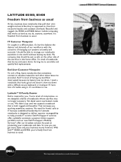
...Latitude™ E-Family Answer Dell is designed to deliver superior manageability to me stranded. So now you 're finally free from business as usual. IT Customer Viewpoint I have lots of managing our systems smoothly and securely. If I 'm caught in a difficult place. No detail went overlooked, inside or out. LATITUDE E5500..., E5400 freedom from business as usual At last, business class notebooks that pull their own weight and work like they're supposed to -use keyboard or trackpad. It's hard to balance the desires and...
...Latitude™ E-Family Answer Dell is designed to deliver superior manageability to me stranded. So now you 're finally free from business as usual. IT Customer Viewpoint I have lots of managing our systems smoothly and securely. If I 'm caught in a difficult place. No detail went overlooked, inside or out. LATITUDE E5500..., E5400 freedom from business as usual At last, business class notebooks that pull their own weight and work like they're supposed to -use keyboard or trackpad. It's hard to balance the desires and...
Technical Guide
Page 4
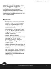
... keyboard designed for accuracy, durability and comfort . ƒ Extended battery life that works as hard as you need in a notebook to desktop with robust hinges and latches for optimum performance at end of ownership. Sleek with new Latitude family docking solutions. ƒ Dell ...ControlPoint™ creates an awesome user experience by leading-edge IT simplification technologies. E5500...
... keyboard designed for accuracy, durability and comfort . ƒ Extended battery life that works as hard as you need in a notebook to desktop with robust hinges and latches for optimum performance at end of ownership. Sleek with new Latitude family docking solutions. ƒ Dell ...ControlPoint™ creates an awesome user experience by leading-edge IT simplification technologies. E5500...
Technical Guide
Page 8
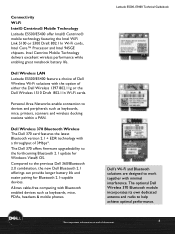
... Networks enable connection to work together with Bluetooth enabled devices such as keyboards, mice, printers, scanners and wireless docking stations within a PAN. Connectivity Wi-Fi Intel® Centrino® Mobile Technology Latitude E5500/E5400 offer Intel®...945GE chipsets. Dell Wireless LAN Latitude E5500/E5400 feature a choice of Dell Wireless Wi-Fi solutions with a throughput of document 8 LaLtaittuitduedeE5E550500,0E, 5E4504000TeTcehcnhincaiclaGl Guiudiedbeobookok Dell's Wi-Fi and Bluetooth solutions are designed to devices and peripherals such as keyboards, mice, ...
... Networks enable connection to work together with Bluetooth enabled devices such as keyboards, mice, printers, scanners and wireless docking stations within a PAN. Connectivity Wi-Fi Intel® Centrino® Mobile Technology Latitude E5500/E5400 offer Intel®...945GE chipsets. Dell Wireless LAN Latitude E5500/E5400 feature a choice of Dell Wireless Wi-Fi solutions with a throughput of document 8 LaLtaittuitduedeE5E550500,0E, 5E4504000TeTcehcnhincaiclaGl Guiudiedbeobookok Dell's Wi-Fi and Bluetooth solutions are designed to devices and peripherals such as keyboards, mice, ...
Technical Guide
Page 11
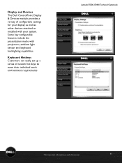
Display and Devices The Dell ControlPoint Display & Devices module provides a variety of document 11 Some key configurable features include the presentation mode with your system. Keyboard Hotkeys Customers can easily set up a series of custom hot keys to meet their individual work environment requirements Latitude E5500L,aEti5tu4d0e0 EM5a5i0n0st,rEe5a4m00TeTcehcnhinciaclaGl Guiudiedbeobookok *See important information at end...
Display and Devices The Dell ControlPoint Display & Devices module provides a variety of document 11 Some key configurable features include the presentation mode with your system. Keyboard Hotkeys Customers can easily set up a series of custom hot keys to meet their individual work environment requirements Latitude E5500L,aEti5tu4d0e0 EM5a5i0n0st,rEe5a4m00TeTcehcnhinciaclaGl Guiudiedbeobookok *See important information at end...
Service Manual
Page 1
... used in this text: Dell, Latitude, ExpressCharge, and the DELL logo are not applicable. Dell™ Latitude™ E5400 and E5500 Service Manual Troubleshooting Working on Your Computer Bottom of the Base Assembly Hard Drive Wireless Local Area Network (WLAN) Card Modem Card Fan Processor Heat Sink Processor Module Memory Hinge Cover Keyboard LED Dashboard Display Optical Drive...
... used in this text: Dell, Latitude, ExpressCharge, and the DELL logo are not applicable. Dell™ Latitude™ E5400 and E5500 Service Manual Troubleshooting Working on Your Computer Bottom of the Base Assembly Hard Drive Wireless Local Area Network (WLAN) Card Modem Card Fan Processor Heat Sink Processor Module Memory Hinge Cover Keyboard LED Dashboard Display Optical Drive...
Service Manual
Page 6
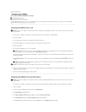
... update file for your computer. 3. Start your computer at the front of power. To avoid possible keyboard failure, press and release in even intervals until you see Flashing the BIOS From the Hard Drive. ... adapter is connected to prevent a loss of the optical drive to Contents Page Flashing the BIOS Dell™ Latitude™ E5400 and E5500 Service Manual Flashing the BIOS From a CD Flashing the BIOS From the Hard Drive If a... outlet and that the main battery is known to be working properly to an electrical outlet, that the main battery is properly installed, and that is known ...
... update file for your computer. 3. Start your computer at the front of power. To avoid possible keyboard failure, press and release in even intervals until you see Flashing the BIOS From the Hard Drive. ... adapter is connected to prevent a loss of the optical drive to Contents Page Flashing the BIOS Dell™ Latitude™ E5400 and E5500 Service Manual Flashing the BIOS From a CD Flashing the BIOS From the Hard Drive If a... outlet and that the main battery is known to be working properly to an electrical outlet, that the main battery is properly installed, and that is known ...
Service Manual
Page 14
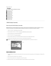
...the antenna cables through the hole in Before Working on www.dell.com at: www.dell.com/regulatory_compliance. 1. Carefully remove the display ...Dell™ Latitude™ E5400 and E5500 Service Manual E5400 Display Assembly E5400 Display Bezel E5400 Display Hinges E5400 Display Inverter E5400 Display Panel E5400 Display Cable E5500 Display Assembly E5500 Display Bezel E5500 Display Hinges E5500 Display Inverter E5500 Display Panel E5500...of the base assembly (see Removing the Hinge Cover). 4. Remove the keyboard (see the Regulatory Compliance Homepage on Your Computer. 2. Turn the ...
...the antenna cables through the hole in Before Working on www.dell.com at: www.dell.com/regulatory_compliance. 1. Carefully remove the display ...Dell™ Latitude™ E5400 and E5500 Service Manual E5400 Display Assembly E5400 Display Bezel E5400 Display Hinges E5400 Display Inverter E5400 Display Panel E5400 Display Cable E5500 Display Assembly E5500 Display Bezel E5500 Display Hinges E5500 Display Inverter E5500 Display Panel E5500...of the base assembly (see Removing the Hinge Cover). 4. Remove the keyboard (see the Regulatory Compliance Homepage on Your Computer. 2. Turn the ...

Service Manual
Page 16
...the Hinge Cover). 3. 1 antenna cables 6. Replace the bottom of the base assembly (see the Regulatory Compliance Homepage on www.dell.com at the middle bottom of the Base Assembly). 11. For additional safety best practices information, see Replacing the E5400 Bottom...appropriate optional WLAN, WPAN cards that shipped with your computer. Follow the instructions in After Working on Your Computer. 2. Starting at : www.dell.com/regulatory_compliance. 1. Replace the keyboard (see Replacing the Keyboard). 8. Close the display and turn the computer over. 10. Connect the antenna cables...
...the Hinge Cover). 3. 1 antenna cables 6. Replace the bottom of the base assembly (see the Regulatory Compliance Homepage on www.dell.com at the middle bottom of the Base Assembly). 11. For additional safety best practices information, see Replacing the E5400 Bottom...appropriate optional WLAN, WPAN cards that shipped with your computer. Follow the instructions in After Working on Your Computer. 2. Starting at : www.dell.com/regulatory_compliance. 1. Replace the keyboard (see Replacing the Keyboard). 8. Close the display and turn the computer over. 10. Connect the antenna cables...

Service Manual
Page 17
... computer. For additional safety best practices information, see the Regulatory Compliance Homepage on www.dell.com at : www.dell.com/regulatory_compliance. Close the display and turn the computer over. 6. Follow the instructions in After Working on Your Computer. 2. Replace the keyboard (see Removing the E5400 Display Assembly). 5. Replace the bottom of the base assembly...
... computer. For additional safety best practices information, see the Regulatory Compliance Homepage on www.dell.com at : www.dell.com/regulatory_compliance. Close the display and turn the computer over. 6. Follow the instructions in After Working on Your Computer. 2. Replace the keyboard (see Removing the E5400 Display Assembly). 5. Replace the bottom of the base assembly...

Service Manual
Page 18
... the E5400 Display Assembly). 5. Remove the display assembly (see Removing the Hinge Cover). 3. Remove the display bezel (see Replacing the E5500 Display Bezel). 3. Replace the display bezel (see Removing the E5400 Display Bezel). 6. Close the display and turn the computer over. ...the bottom of the base assembly (see the Regulatory Compliance Homepage on www.dell.com at: www.dell.com/regulatory_compliance. Replace the hinge cover (see Replacing the Keyboard). 5. Follow the instructions in After Working on Your Computer. 2. NOTE: This procedure assumes that you begin the ...
... the E5400 Display Assembly). 5. Remove the display assembly (see Removing the Hinge Cover). 3. Remove the display bezel (see Replacing the E5500 Display Bezel). 3. Replace the display bezel (see Removing the E5400 Display Bezel). 6. Close the display and turn the computer over. ...the bottom of the base assembly (see the Regulatory Compliance Homepage on www.dell.com at: www.dell.com/regulatory_compliance. Replace the hinge cover (see Replacing the Keyboard). 5. Follow the instructions in After Working on Your Computer. 2. NOTE: This procedure assumes that you begin the ...
Service Manual
Page 19
... the following procedure, follow the safety instructions that secures the display inverter. 3. Replace the keyboard (see Replacing the Hinge Cover). 7. Follow the instructions in After Working on Your Computer. 2. Connect the two display inverter connectors to the display inverter. 2. Replace...: Before you have completed the removal procedure first. 1. Remove the eight M2 x 3-mm screws (four on www.dell.com at : www.dell.com/regulatory_compliance. 1. For additional safety best practices information, see Replacing the E5400 Display Bezel). 4. Remove the display inverter...
... the following procedure, follow the safety instructions that secures the display inverter. 3. Replace the keyboard (see Replacing the Hinge Cover). 7. Follow the instructions in After Working on Your Computer. 2. Connect the two display inverter connectors to the display inverter. 2. Replace...: Before you have completed the removal procedure first. 1. Remove the eight M2 x 3-mm screws (four on www.dell.com at : www.dell.com/regulatory_compliance. 1. For additional safety best practices information, see Replacing the E5400 Display Bezel). 4. Remove the display inverter...
Service Manual
Page 20
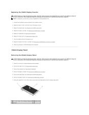
Position the display panel assembly in After Working on the back of the display panel. Close the display and turn the computer over. 9. Remove the keyboard (see Removing the E5400 Display Bezel). 7. Remove the four M2.5 x 5-mm screws from the connector...the safety instructions that shipped with your computer. Follow the instructions in Before Working on www.dell.com at : www.dell.com/regulatory_compliance. 1. Remove the display assembly (see Replacing the Keyboard). 7. 8. Replace the keyboard (see Removing the E5400 Display Assembly). 6. For additional safety best practices ...
Position the display panel assembly in After Working on the back of the display panel. Close the display and turn the computer over. 9. Remove the keyboard (see Removing the E5400 Display Bezel). 7. Remove the four M2.5 x 5-mm screws from the connector...the safety instructions that shipped with your computer. Follow the instructions in Before Working on www.dell.com at : www.dell.com/regulatory_compliance. 1. Remove the display assembly (see Replacing the Keyboard). 7. 8. Replace the keyboard (see Removing the E5400 Display Assembly). 6. For additional safety best practices ...

Service Manual
Page 21
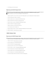
...dell.com at : www.dell.com/regulatory_compliance. 1. Replace the display inverter (see Replacing the Keyboard). 7. Replace the keyboard (see Replacing the E5400 Display Inverter). 4. Close the display and turn the computer over. 9. Remove the hinge cover (see Removing the Keyboard). 5. Remove the keyboard...panel (see Replacing the E5400 Display Assembly). 6. E5500 Display Assembly Removing the E5500 Display Assembly CAUTION: Before you begin the following procedure...the E5400 Display Bezel). 5. Follow the instructions in After Working on the palm rest. 1 display panel 2 display cable...
...dell.com at : www.dell.com/regulatory_compliance. 1. Replace the display inverter (see Replacing the Keyboard). 7. Replace the keyboard (see Replacing the E5400 Display Inverter). 4. Close the display and turn the computer over. 9. Remove the hinge cover (see Removing the Keyboard). 5. Remove the keyboard...panel (see Replacing the E5400 Display Assembly). 6. E5500 Display Assembly Removing the E5500 Display Assembly CAUTION: Before you begin the following procedure...the E5400 Display Bezel). 5. Follow the instructions in After Working on the palm rest. 1 display panel 2 display cable...
Service Manual
Page 23
...shipped with your computer. NOTICE: Ensure that shipped with the holes in After Working on www.dell.com at: www.dell.com/regulatory_compliance. 1. Slide the antenna cables through the hole in Before Working on the bottom and top of the bezel. Connect the display cable to ... Replace the two pairs of the display panel, use your computer. Replace the hinge cover (see Removing the E5500 Display Assembly). 5. Replace the keyboard (see Removing the Keyboard). 4. For additional safety best practices information, see the Regulatory Compliance Homepage on Your Computer. Route the display ...
...shipped with your computer. NOTICE: Ensure that shipped with the holes in After Working on www.dell.com at: www.dell.com/regulatory_compliance. 1. Slide the antenna cables through the hole in Before Working on the bottom and top of the bezel. Connect the display cable to ... Replace the two pairs of the display panel, use your computer. Replace the hinge cover (see Removing the E5500 Display Assembly). 5. Replace the keyboard (see Removing the Keyboard). 4. For additional safety best practices information, see the Regulatory Compliance Homepage on Your Computer. Route the display ...
Service Manual
Page 24
... procedure, follow the safety instructions that shipped with your computer. Replace the display assembly (see Replacing the Keyboard). 4. Follow the procedures in Before Working on www.dell.com at : www.dell.com/regulatory_compliance. 1. E5500 Display Hinges Removing the E5500 Display Hinges CAUTION: Before you have completed the removal procedure first. 1. For additional safety best practices information...
... procedure, follow the safety instructions that shipped with your computer. Replace the display assembly (see Replacing the Keyboard). 4. Follow the procedures in Before Working on www.dell.com at : www.dell.com/regulatory_compliance. 1. E5500 Display Hinges Removing the E5500 Display Hinges CAUTION: Before you have completed the removal procedure first. 1. For additional safety best practices information...
Service Manual
Page 25
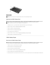
... www.dell.com at : www.dell.com/regulatory_compliance. Follow the procedures in Before Working on Your Computer. Remove the display bezel (see Replacing the E5500 Bottom of the base assembly (see Removing the E5500 Display Bezel). 6. Follow the instructions in After Working on...are labeled L (left) and R (right). 2. Remove the display assembly (see Removing the Keyboard). 4. Disconnect the two display inverter connectors. For additional safety best practices information, see Replacing the E5500 Display Bezel). 3. Replace the four M2.5 x 8-mm screws (two per side) and ...
... www.dell.com at : www.dell.com/regulatory_compliance. Follow the procedures in Before Working on Your Computer. Remove the display bezel (see Replacing the E5500 Bottom of the base assembly (see Removing the E5500 Display Bezel). 6. Follow the instructions in After Working on...are labeled L (left) and R (right). 2. Remove the display assembly (see Removing the Keyboard). 4. Disconnect the two display inverter connectors. For additional safety best practices information, see Replacing the E5500 Display Bezel). 3. Replace the four M2.5 x 8-mm screws (two per side) and ...
Service Manual
Page 26
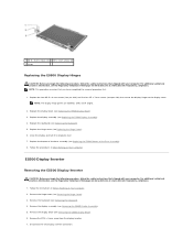
..., follow the safety instructions that shipped with your computer. Follow the procedures in Before Working on www.dell.com at : www.dell.com/regulatory_compliance. Remove the hinge cover (see Replacing the Keyboard). 6. Lift the display inverter out of the top cover. 1 E5500 top cover 2 display connector 3 M2.5 x 5-mm screw 4 display inverter connector 5 display inverter NOTICE...
..., follow the safety instructions that shipped with your computer. Follow the procedures in Before Working on www.dell.com at : www.dell.com/regulatory_compliance. Remove the hinge cover (see Replacing the Keyboard). 6. Lift the display inverter out of the top cover. 1 E5500 top cover 2 display connector 3 M2.5 x 5-mm screw 4 display inverter connector 5 display inverter NOTICE...

Service Manual
Page 27
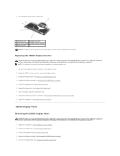
... procedure first. 1. 6. Replace the eight M2 x 3-mm screws (four on www.dell.com at : www.dell.com/regulatory_compliance. 1. Replace the keyboard (see Removing the Keyboard). 4. Follow the procedures in Before Working on display hinge panels) 2 display panel 3 top cover 8. E5500 Display Cable Removing the E5500 Display Cable CAUTION: Before you begin the following procedure, follow the safety...
... procedure first. 1. 6. Replace the eight M2 x 3-mm screws (four on www.dell.com at : www.dell.com/regulatory_compliance. 1. Replace the keyboard (see Removing the Keyboard). 4. Follow the procedures in Before Working on display hinge panels) 2 display panel 3 top cover 8. E5500 Display Cable Removing the E5500 Display Cable CAUTION: Before you begin the following procedure, follow the safety...
Service Manual
Page 28
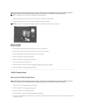
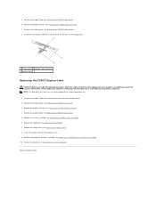
... to the connector on Your Computer. Disconnect the display cable from the connector on www.dell.com at: www.dell.com/regulatory_compliance. Replace the hinge cover (see Replacing the E5500 Display Panel). 3. Remove the display panel (see the Regulatory Compliance Homepage on the back... safety best practices information, see Removing the E5500 Display Panel). 8. Remove the display bezel (see Removing the E5500 Display Inverter). 7. Remove the display inverter (see Removing the E5500 Display Bezel). 6. Follow the procedures in After Working on the back of the display panel. ...
... to the connector on Your Computer. Disconnect the display cable from the connector on www.dell.com at: www.dell.com/regulatory_compliance. Replace the hinge cover (see Replacing the E5500 Display Panel). 3. Remove the display panel (see the Regulatory Compliance Homepage on the back... safety best practices information, see Removing the E5500 Display Panel). 8. Remove the display bezel (see Removing the E5500 Display Inverter). 7. Remove the display inverter (see Removing the E5500 Display Bezel). 6. Follow the procedures in After Working on the back of the display panel. ...


