
Service Manual
Page 12
Hard-Disk Drive: M3 x 5 (1 each) Keyboard Assembly: M2.5 x 10 (7 each) Display Assembly: M2.5 x 4 (3 each) Display Assembly Bezel: Rubber Screw Covers (4 each) Plastic Screw Covers (2 each) Display Assembly Bezel: M2.5 x 4 (6 each) 14.1 ...: M3 x 3 (3 each) Palmrest Assembly: M2.5 x 20 (5 each) System Board: M2.5 x 4 (2 each) Microprocessor Shield: 3 captive and 2 removable screws M2 x 3 (2 each) TCA and Exhaust Fan: M2.5 x 4 (2 each) 4 Dell Latitude CPt V-Series/CPx H-Series Service Manual
Hard-Disk Drive: M3 x 5 (1 each) Keyboard Assembly: M2.5 x 10 (7 each) Display Assembly: M2.5 x 4 (3 each) Display Assembly Bezel: Rubber Screw Covers (4 each) Plastic Screw Covers (2 each) Display Assembly Bezel: M2.5 x 4 (6 each) 14.1 ...: M3 x 3 (3 each) Palmrest Assembly: M2.5 x 20 (5 each) System Board: M2.5 x 4 (2 each) Microprocessor Shield: 3 captive and 2 removable screws M2 x 3 (2 each) TCA and Exhaust Fan: M2.5 x 4 (2 each) 4 Dell Latitude CPt V-Series/CPx H-Series Service Manual
Service Manual
Page 16
... KYBD, 88, NOR, D-PTG Keyboard, Portuguese KYBD,88,PORTUGUESE,D-PTG Keyboard, Russian KYBD, 87, RUS, D-PTG Keyboard, Spanish KYBD, 88, SPN, D-PTG Keyboard, Swedish/Finnish KYBD, 88, SWE, D-PTG Keyboard, Swiss KYBD, 88, SWI, D-PTG Keyboard, Thai KYBD, 87, THAI, D-PTG Keyboard, English (U.K.) KYBD, 88, UK, D-PTG Keyboard, English (U.S.) KYBD, 87, DOM, D-PTG 8 Dell Latitude CPt V-Series/CPx H-Series Service Manual
... KYBD, 88, NOR, D-PTG Keyboard, Portuguese KYBD,88,PORTUGUESE,D-PTG Keyboard, Russian KYBD, 87, RUS, D-PTG Keyboard, Spanish KYBD, 88, SPN, D-PTG Keyboard, Swedish/Finnish KYBD, 88, SWE, D-PTG Keyboard, Swiss KYBD, 88, SWI, D-PTG Keyboard, Thai KYBD, 87, THAI, D-PTG Keyboard, English (U.K.) KYBD, 88, UK, D-PTG Keyboard, English (U.S.) KYBD, 87, DOM, D-PTG 8 Dell Latitude CPt V-Series/CPx H-Series Service Manual
Service Manual
Page 18
..., PLSTC Speaker (2 each) SPKR, 20X40, 1W, 8OHMS Display assembly 14.1-inch LCD panel 12.1-inch LCD panel 12.1-inch LCD inverter LCD hinge LCD bezel Keyboard Hard-disk drive carrier Microprocessor shield/ thermal cooling assembly arm Thermal cooling assembly Palmrest System board assembly SCR, M2.5x4, PHH, LP, ZPS SCR, M2X3..., ZPS SCR, M2.5X20, PHH, LP, ZPS SCR, M2.5X4, PHH, LP, ZPS 13 14 15 15, 17 13 14 9 6 12 23 19 22 10 Dell Latitude CPt V-Series/CPx H-Series Service Manual
..., PLSTC Speaker (2 each) SPKR, 20X40, 1W, 8OHMS Display assembly 14.1-inch LCD panel 12.1-inch LCD panel 12.1-inch LCD inverter LCD hinge LCD bezel Keyboard Hard-disk drive carrier Microprocessor shield/ thermal cooling assembly arm Thermal cooling assembly Palmrest System board assembly SCR, M2.5x4, PHH, LP, ZPS SCR, M2X3..., ZPS SCR, M2.5X20, PHH, LP, ZPS SCR, M2.5X4, PHH, LP, ZPS 13 14 15 15, 17 13 14 9 6 12 23 19 22 10 Dell Latitude CPt V-Series/CPx H-Series Service Manual

Service Manual
Page 20
display assembly keyboard palmrest assembly hard-disk drive system board main battery bottom case assembly modular bay device The following subsections provide instructions for removing and replacing field-replaceable parts and assemblies. 12 Dell Latitude CPt V-Series/CPx H-Series Service Manual
display assembly keyboard palmrest assembly hard-disk drive system board main battery bottom case assembly modular bay device The following subsections provide instructions for removing and replacing field-replaceable parts and assemblies. 12 Dell Latitude CPt V-Series/CPx H-Series Service Manual
Service Manual
Page 23
...'s edge connector with the slot in the socket. To release a memory module from the socket (it . NOTE: 192-MB memory modules are not interchangeable. support.dell.com Dell Latitude CPt V-Series/CPx H-Series Service Manual 15 To remove the keyboard assembly, perform the following steps. 1.
...'s edge connector with the slot in the socket. To release a memory module from the socket (it . NOTE: 192-MB memory modules are not interchangeable. support.dell.com Dell Latitude CPt V-Series/CPx H-Series Service Manual 15 To remove the keyboard assembly, perform the following steps. 1.

Service Manual
Page 24
Remove the seven 10-mm screws, labeled with a "circle K," that secure the keyboard to the computer (see Figure 10), and lift the right edge of the blank key (see Figure 9). 3. Release the keyboard from the palmrest assembly by inserting a small flat-blade screwdriver under the edge of the keyboard. 16 Dell Latitude CPt V-Series/CPx H-Series Service Manual 10-mm screws (7) M2.5x10 2. Turn the computer right-side up and open the display. 4.
Remove the seven 10-mm screws, labeled with a "circle K," that secure the keyboard to the computer (see Figure 10), and lift the right edge of the blank key (see Figure 9). 3. Release the keyboard from the palmrest assembly by inserting a small flat-blade screwdriver under the edge of the keyboard. 16 Dell Latitude CPt V-Series/CPx H-Series Service Manual 10-mm screws (7) M2.5x10 2. Turn the computer right-side up and open the display. 4.
Service Manual
Page 25
support.dell.com Dell Latitude CPt V-Series/CPx H-Series Service Manual 17 track stick keyboard scalloped edge of the palmrest. 6. Rest the key face of the computer (see Figure 11). Rotate the keyboard over its left side of the keyboard on the left edge. 7. Lift the keyboard out of blank key palmrest 5.
support.dell.com Dell Latitude CPt V-Series/CPx H-Series Service Manual 17 track stick keyboard scalloped edge of the palmrest. 6. Rest the key face of the computer (see Figure 11). Rotate the keyboard over its left side of the keyboard on the left edge. 7. Lift the keyboard out of blank key palmrest 5.
Service Manual
Page 26
.... Ensure that the contact side of the computer with its key face down when you lower the keyboard into place. Remove the keyboard assembly. Carefully turn the keyboard over and fit the keyboard into the palmrest. 18 Dell Latitude CPt V-Series/CPx H-Series Service Manual Carefully disconnect the track stick cable from the connector on the left...
.... Ensure that the contact side of the computer with its key face down when you lower the keyboard into place. Remove the keyboard assembly. Carefully turn the keyboard over and fit the keyboard into the palmrest. 18 Dell Latitude CPt V-Series/CPx H-Series Service Manual Carefully disconnect the track stick cable from the connector on the left...
Service Manual
Page 27
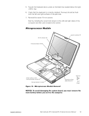
... located below the right key. 6. Check that the keyboard is correctly installed. The keys should be flush with the left and right sides of the palmrest. 7. To push the keyboard down, press on the microprocessor board (2) microprocessor module M2.0x3 thermal cooling assembly arm support.dell.com Dell Latitude CPt V-Series/CPx H-Series Service Manual 19
... located below the right key. 6. Check that the keyboard is correctly installed. The keys should be flush with the left and right sides of the palmrest. 7. To push the keyboard down, press on the microprocessor board (2) microprocessor module M2.0x3 thermal cooling assembly arm support.dell.com Dell Latitude CPt V-Series/CPx H-Series Service Manual 19

Service Manual
Page 28
...module aligned with white marks on the microprocessor shield that secure the thermal cooling assembly to secure the microprocessor module and shield. 20 Dell Latitude CPt V-Series/CPx H-Series Service Manual When you reinstall the microprocessor module in the system board, make sure that you align the ...microprocessor connector on the left side of the shield to the microprocessor module (see Figure 12). Remove the main battery. 2. Remove the keyboard assembly. 3. Tighten the three captive screws on the metal plate that secure the thermal cooling assembly arm and shield to the corner ...
...module aligned with white marks on the microprocessor shield that secure the thermal cooling assembly to secure the microprocessor module and shield. 20 Dell Latitude CPt V-Series/CPx H-Series Service Manual When you reinstall the microprocessor module in the system board, make sure that you align the ...microprocessor connector on the left side of the shield to the microprocessor module (see Figure 12). Remove the main battery. 2. Remove the keyboard assembly. 3. Tighten the three captive screws on the metal plate that secure the thermal cooling assembly arm and shield to the corner ...

Service Manual
Page 29
Disconnect the LCD flex cable from the back of the computer (see Figure 13). 4. support.dell.com Dell Latitude CPt V-Series/CPx H-Series Service Manual 21 Remove the three 4-mm screws, labeled with a "circle D," from the connector on the system board by pulling the connector straight up. Open the display. 5. display assembly hinge cover LCD flex cable snap tab bottom case assembly 4-mm screws (3) snap tab M2.5x4 1. Close the display. 3. Remove the keyboard. 2.
Disconnect the LCD flex cable from the back of the computer (see Figure 13). 4. support.dell.com Dell Latitude CPt V-Series/CPx H-Series Service Manual 21 Remove the three 4-mm screws, labeled with a "circle D," from the connector on the system board by pulling the connector straight up. Open the display. 5. display assembly hinge cover LCD flex cable snap tab bottom case assembly 4-mm screws (3) snap tab M2.5x4 1. Close the display. 3. Remove the keyboard. 2.

Service Manual
Page 31
Separate the bezel from the bottom of the display assembly. 2. Remove the keyboard. 3. Disconnect the ZIF connector and the display-assembly interface cable connector (see Figure 14). 3. support.dell.com Dell Latitude CPt V-Series/CPx H-Series Service Manual 23 Use a scribe to carefully pry the two plastic screw covers out of the two screw holes located...
Separate the bezel from the bottom of the display assembly. 2. Remove the keyboard. 3. Disconnect the ZIF connector and the display-assembly interface cable connector (see Figure 14). 3. support.dell.com Dell Latitude CPt V-Series/CPx H-Series Service Manual 23 Use a scribe to carefully pry the two plastic screw covers out of the two screw holes located...

Service Manual
Page 33
rubber screw covers (4) 4-mm screws (6) plastic screw covers (2) display assembly bezel 5-mm screws (4) LCD panel LCD flex cable display-assembly top cover back-light plug latch inverter ZIF connector 3-mm screws (3) M3.0x3 M2.5x4 M3.0x5 To remove the 12.1-inch display LCD panel, perform the following steps: 1. support.dell.com Dell Latitude CPt V-Series/CPx H-Series Service Manual 25 Remove the display assembly bezel. 5. Remove the four 5-mm screws securing the LCD panel to the top cover. Remove the main battery. 2. Remove the display assembly. 4. Remove the keyboard. 3.
rubber screw covers (4) 4-mm screws (6) plastic screw covers (2) display assembly bezel 5-mm screws (4) LCD panel LCD flex cable display-assembly top cover back-light plug latch inverter ZIF connector 3-mm screws (3) M3.0x3 M2.5x4 M3.0x5 To remove the 12.1-inch display LCD panel, perform the following steps: 1. support.dell.com Dell Latitude CPt V-Series/CPx H-Series Service Manual 25 Remove the display assembly bezel. 5. Remove the four 5-mm screws securing the LCD panel to the top cover. Remove the main battery. 2. Remove the display assembly. 4. Remove the keyboard. 3.

Service Manual
Page 38
Remove the main battery. 2. Remove the five 20-mm screws that secure the palmrest to the computer. Remove the keyboard. 4. These screws, labeled with a "circle P," are located underneath the front edge of the computer (see Figure 18). 7. Turn the computer right-side up on a flat work surface. 30 Dell Latitude CPt V-Series/CPx H-Series Service Manual Remove the display assembly. 5. Turn the computer upside down on the work surface. 6. Remove the device from the modular bay. 3. 20-mm screws (5) M2.5x20 1.
Remove the main battery. 2. Remove the five 20-mm screws that secure the palmrest to the computer. Remove the keyboard. 4. These screws, labeled with a "circle P," are located underneath the front edge of the computer (see Figure 18). 7. Turn the computer right-side up on a flat work surface. 30 Dell Latitude CPt V-Series/CPx H-Series Service Manual Remove the display assembly. 5. Turn the computer upside down on the work surface. 6. Remove the device from the modular bay. 3. 20-mm screws (5) M2.5x20 1.

Service Manual
Page 39
Remove the main battery. 2. Remove the palmrest assembly. Remove the keyboard assembly. 4. Remove the display assembly. 5. Disconnect the palmrest flexible cable from the touch-pad connector on the system board (see Figure 19). 1. Remove the device from the bottom case assembly (see Figure 19). Carefully remove the palmrest assembly from the modular bay. 3. support.dell.com Dell Latitude CPt V-Series/CPx H-Series Service Manual 31 palmrest assembly palmrest flexible cable touch-pad connector bottom case assembly 9. 8.
Remove the main battery. 2. Remove the palmrest assembly. Remove the keyboard assembly. 4. Remove the display assembly. 5. Disconnect the palmrest flexible cable from the touch-pad connector on the system board (see Figure 19). 1. Remove the device from the bottom case assembly (see Figure 19). Carefully remove the palmrest assembly from the modular bay. 3. support.dell.com Dell Latitude CPt V-Series/CPx H-Series Service Manual 31 palmrest assembly palmrest flexible cable touch-pad connector bottom case assembly 9. 8.

Service Manual
Page 41
...with the wear ribs is facing the bottom of the computer. Repeat steps 6 through 8 for the system board assembly includes a support.dell.com Dell Latitude CPt V-Series/CPx H-Series Service Manual 33 Remove the palmrest assembly. 6. Remove the device from the outside of the case. Remove the ... right side. Remove the main battery. 2. Ensure that the newly installed latch moves smoothly and freely when pushed and released. 9. Remove the keyboard assembly. 4. bump side wear ribs (2) The system board's basic input/output system (BIOS) chip contains the system service tag number, which...
...with the wear ribs is facing the bottom of the computer. Repeat steps 6 through 8 for the system board assembly includes a support.dell.com Dell Latitude CPt V-Series/CPx H-Series Service Manual 33 Remove the palmrest assembly. 6. Remove the device from the outside of the case. Remove the ... right side. Remove the main battery. 2. Ensure that the newly installed latch moves smoothly and freely when pushed and released. 9. Remove the keyboard assembly. 4. bump side wear ribs (2) The system board's basic input/output system (BIOS) chip contains the system service tag number, which...

Service Manual
Page 42
Remove the main battery. 2. Remove the keyboard assembly. 4. Remove the microprocessor module. 7. Verify that outline the captive washers. 34 Dell Latitude CPt V-Series/CPx H-Series Service Manual The 4-mm screw with captive washer located on the far left side of the microprocessor module. Remove the display assembly. 5. ...
Remove the main battery. 2. Remove the keyboard assembly. 4. Remove the microprocessor module. 7. Verify that outline the captive washers. 34 Dell Latitude CPt V-Series/CPx H-Series Service Manual The 4-mm screw with captive washer located on the far left side of the microprocessor module. Remove the display assembly. 5. ...

Service Manual
Page 44
Remove the keyboard assembly. 4. Remove the main battery. 2. Remove the system board assembly. 8. Remove the two 4-mm screws securing the thermal cooling assembly and exhaust fan, and then remove the thermal cooling assembly and exhaust fan (see Figure 20). 36 Dell Latitude CPt V-Series/CPx H-Series Service Manual Remove the display assembly. 5. Remove the device...
Remove the keyboard assembly. 4. Remove the main battery. 2. Remove the system board assembly. 8. Remove the two 4-mm screws securing the thermal cooling assembly and exhaust fan, and then remove the thermal cooling assembly and exhaust fan (see Figure 20). 36 Dell Latitude CPt V-Series/CPx H-Series Service Manual Remove the display assembly. 5. Remove the device...

Service Manual
Page 46
hard-disk drive assembly removal, 13 palmrest assembly removal, 29 inverter, 12.1-inch LCD panel removal, 26 replacement, 27 keyboard assembly removal, 16 memory module removal, 14 memory module cover removal, 14 microprocessor module removal, 19 modular bay devices removal, 13 module latch assemblies removal, ... module, 14 SuperDisk LS-120 drive removal, 13 system board assembly removal, 19 thermal cooling assembly removal, 36 tools, 2 travel module removal, 13 ZIF connectors, 5 2 Dell Latitude CPt V-Series/CPx H-Series Service Manual
hard-disk drive assembly removal, 13 palmrest assembly removal, 29 inverter, 12.1-inch LCD panel removal, 26 replacement, 27 keyboard assembly removal, 16 memory module removal, 14 memory module cover removal, 14 microprocessor module removal, 19 modular bay devices removal, 13 module latch assemblies removal, ... module, 14 SuperDisk LS-120 drive removal, 13 system board assembly removal, 19 thermal cooling assembly removal, 36 tools, 2 travel module removal, 13 ZIF connectors, 5 2 Dell Latitude CPt V-Series/CPx H-Series Service Manual


