Get support for Dell Latitude CPt V

Dell Latitude CPt V Support Question

Dell Latitude CPt V Support Question

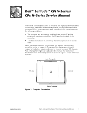
Find answers below for this question about Dell Latitude CPt V.
Need a Dell Latitude CPt V manual? We have 1 online manual for this item!
Question posted by adamseiver on June 16th, 2011

My Laptop Is Running Hot With Loud Fan On All The Time.

Where is the microprocessor located in the D430 latitude laptop?  My device is running hot in the right corner behind the backspace key and the fan is on and loud all the time.   Thanks,   Adam

Current Answers

Answer #1: Posted by kcmjr on June 16th, 2011 12:13 PM
This answer was accepted by the poster of the original question.
kcmjr

Member since:
May 5th, 2011

Points: 4,254,255
1,090
points
Here is a service manual you can look at if you like: http://www.elhvb.com/mobokive/edwin/laptops/Dell/LATITUDE/CPTV/5169T_EN.PDF

It shows where everything is and how to disassemble the entire laptop.

The processor is located on the right side about where the Enter and Backspace keys are located.

Laptops are prone to cooling issues.  This one uses a thermal transfer heat-pipe system to cool the CPU.  In most cases heat-pipes are a great way to transfer heat around.  In this case I would expect the area above and below the CPU to get quite hot just by the nature of the design.  Heat pipes work nest when vertical, this one is horizontal which while not ideal should still work.

Make sure that the vents are not being covered up.  Holdijng the laptop on your lap ironically is one of the worst places to use it.  Your legs tend to block the cooling vents.  Also make sure that the vents are not clogged with dust.

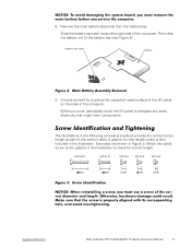
It's possible that the fan is dying.  They should be fairly quiet and when they start making noise it's because the ball bearings are burning out.  A service shop (or you if you're technical) can replace the colling unit as described in the service guide.


Licenses & Certifications: Microsoft, Cisco, VMware, Novell, FCC RF & Amateur Radio licensed.

Related Dell Latitude CPt V Manual Pages

Service Manual - Page 4

... Corporation disclaims any manner whatsoever without notice. © 1999 Dell Computer Corporation. Reproduction in any proprietary interest in this text: Dell, the DELL logo, and Latitude are trademarks of Dell Computer Corporation is subject to either the entities claiming the marks and names or their products. A00 Trademarks used in this...
Service Manual - Page 9

... book or something similar to exceed 180 degrees. Unless otherwise noted, each procedure in this manual, the locations or directions relative to the bottom case should never be replaced by performing the removal procedure in Figure 1... in reverse order. back of computer left side right side front of computer support.dell.com Dell Latitude CPt V-Series/CPx H-Series Service Manual 1
Service Manual - Page 10

... the computer using the computer's operating system, press the power button for personal injury or shock. Disconnect the computer and any installed PC Cards. 2 Dell Latitude CPt V-Series/CPx H-Series Service Manual Disconnect all open application programs. 2. Remove any attached peripherals from their electrical outlets to work in progress and close all...
Service Manual - Page 11

... toward the right side of the battery bay (see Figure 2). Examples are shown in the following removal procedures provide the correct screw length as part of the I /O panel to check for that might harm components. M2.5x20 M2.5x10 M3.0x5 M2.5x4 M2.0x3 support.dell.com Dell Latitude CPt V-Series/CPx...
Service Manual - Page 12

... Latitude CPt V-Series/CPx H-Series Service Manual When you are removing and replacing components, photocopy the Table 1 placement mat as a tool to Top Cover: M3 x 5 (4 each) 12.1-Inch Display Assembly Inverter: M3 x 3 (3 each) Palmrest Assembly: M2.5 x 20 (5 each) System Board: M2.5 x 4 (2 each) Microprocessor Shield: 3 captive and 2 removable screws M2 x 3 (2 each) TCA and Exhaust Fan...
Service Manual - Page 13

... connector. These connectors are zero insertion force (ZIF) connectors. To reconnect an interface cable to a ZIF connector, perform the following steps: 1. support.dell.com Dell Latitude CPt V-Series/CPx H-Series Service Manual 5 Insert a small flat-blade screwdriver behind the movable part of the cable into the connector. 3. Orient the end of the...
Service Manual - Page 14

..., 24X, TSHBA PWA, INTERCONN, CD/DVD, OMAHA ASSY, BTM/BZL, CD, 24X, TSHBA ASSY, HSG, PLSTC, CD/DVD, OMHA LBL, CD, MEDIA BAY, TSHB 6 Dell Latitude CPt V-Series/CPx H-Series Service Manual
Service Manual - Page 15

... 23 (includes fan) Hard-disk drive, subassembly SUBASSY, HD, xxxxx, yyyMM, zzz* 6 Hard-disk drive HD, xxxxx, I, F2, yyMM, zzz* Hard-disk drive interface PWA, INTERCONN, HD, CRNA board * Substitute the drive capacity for xxxxx, the drive height for yy, and the manufacturer for zzz. support.dell.com Dell Latitude CPt V-Series/CPx...
Service Manual - Page 16

... Keyboard, Swiss KYBD, 88, SWI, D-PTG Keyboard, Thai KYBD, 87, THAI, D-PTG Keyboard, English (U.K.) KYBD, 88, UK, D-PTG Keyboard, English (U.S.) KYBD, 87, DOM, D-PTG 8 Dell Latitude CPt V-Series/CPx H-Series Service Manual
Service Manual - Page 17

....1-inch display 14.1-inch display top cover 12.1-inch display top cover 14.1-inch flex cable 12.1-inch flex cable 12.1-inch display bezel Right hinge Left hinge ASSY, CVR, TOP, LCD, CRNA CVR, TOP, LCD, TFT, CRNA ASSY, CVR, TOP, LCD, 12.1,... drive capacity for xxxxx, the drive height for yy, and the manufacturer for zzz. support.dell.com Dell Latitude CPt V-Series/CPx H-Series Service Manual 9
Service Manual - Page 18

... Display assembly 14.1-inch LCD panel 12.1-inch LCD panel 12.1-inch LCD inverter LCD hinge LCD bezel Keyboard Hard-disk drive carrier Microprocessor shield/ thermal cooling assembly arm Thermal cooling assembly Palmrest System board assembly SCR, M2.5x4, PHH, LP, ZPS SCR, M2X3,... M2.5X4, PHH, LP, ZPS 13 14 15 15, 17 13 14 9 6 12 23 19 22 10 Dell Latitude CPt V-Series/CPx H-Series Service Manual
Service Manual - Page 19

..., SVC, PRM, PCA xxx MHz 12 Service Kit Microprocessor shield ASSY, SHLD, EMI, PRC, MET 12 Service Kit, latch, slider, LTCH, BTN, Module Button Foot, Rubber, Black (4 each) Foot, Rbr, Blk Foot, Rubber, Strike Zone, Black Foot, Rbr, Strike Zone, Blk support.dell.com Dell Latitude CPt V-Series/CPx H-Series Service Manual 11
Service Manual - Page 20

display assembly keyboard palmrest assembly hard-disk drive system board main battery bottom case assembly modular bay device The following subsections provide instructions for removing and replacing field-replaceable parts and assemblies. 12 Dell Latitude CPt V-Series/CPx H-Series Service Manual
Service Manual - Page 21

Turn the computer over, and remove the 5-mm screw from the center of the computer. 2. The drive is on the left side of the hard-disk drive door (see Figure 6). latch lock support.dell.com Dell Latitude CPt V-Series/CPx H-Series Service Manual 13 Slide the drive door up and pull the drive out of computer 5-mm screw M3.0x5 hard-disk drive door 1. bottom of the computer.
Service Manual - Page 22

... display and turn the computer upside down on a flat work surface. 2. Keep holding the latch open while pulling the device out of the modular bay with the other hand (see Figure 7). 1. inner tabs (2 per socket) DIMM A DIMM...Release the memory module cover. Remove the memory module cover. 14 Dell Latitude CPt V-Series/CPx H-Series Service Manual Push the module latch toward the unlock icon.
Service Manual - Page 23

...can be firmly seated only one way. Close the display assembly, and turn the computer upside down on the system board are keyed, or designed to disengage from its socket. To release a memory module from the socket (it should pop up slightly) ...the memory module down does not fit properly in the DIMM A socket. support.dell.com Dell Latitude CPt V-Series/CPx H-Series Service Manual 15
Service Manual - Page 24

Release the keyboard from the palmrest assembly by inserting a small flat-blade screwdriver under the edge of the keyboard. 16 Dell Latitude CPt V-Series/CPx H-Series Service Manual Turn the computer right-side up and open the display. 4. 10-mm screws (7) M2.5x10 2. Remove the seven 10-mm screws, labeled with a "circle K," that secure...
Service Manual - Page 25

track stick keyboard scalloped edge of the computer (see Figure 11). Rotate the keyboard over its left side of blank key palmrest 5. support.dell.com Dell Latitude CPt V-Series/CPx H-Series Service Manual 17 Rest the key face of the keyboard on the left edge. 7. Lift the keyboard out of the palmrest. 6.
Service Manual - Page 28

... the module are higher than the others, the module is directly over this corner to secure the microprocessor module and shield. 20 Dell Latitude CPt V-Series/CPx H-Series Service Manual Remove the main battery. 2. Pay attention to the microprocessor module. 1. Replace the two 3-mm screws that secure the thermal cooling assembly arm and shield to...
Service Manual - Page 44

... 4-mm screws securing the thermal cooling assembly and exhaust fan, and then remove the thermal cooling assembly and exhaust fan (see Figure 20). 36 Dell Latitude CPt V-Series/CPx H-Series Service Manual Remove the display assembly. 5. Remove the system board assembly. 8. Remove the microprocessor module. 7. Remove the device from the connector on the system board. 9. 4-mm...

Similar Questions

Ask a New Question
Use the box below to post a new question about this Dell product .
Points & Prizes
  • You can earn points for nearly everything you do on HelpOwl.com
  • You can trade in those points for gift cards at leading retailers such as Amazon.com and Walmart
  • It's that simple!
See How it Works
Create a Free Account

Dell Manuals

Find free Dell Latitude CPt V manuals and user guides available at ManualOwl.com. Try out our unique manual viewer allowing you to interact with manuals from directly within your browser!

Dell Reviews

View thousands of Dell user reviews and customer ratings available at ReviewOwl.com.

Contact Information

Complete Dell customer service contact information including steps to reach representatives, hours of operation, customer support links and more from ContactHelp.com.

Scoreboard Ratings

See detailed Dell customer service rankings, employee comments and much more from our sister site.

Dell Recalls

Find comprehensive Dell recall information updated hourly on RecallOwl.com.