Service Manual
Page 5
Contents 1 Before You Begin Preparing to Work Inside the Computer 8 Recommended Tools 9 Screw Identification 1 0 2 Removing and Replacing Parts System Components 1 4 Hard Drive 1 5 Removing the Hard Drive 1 6 Replacing the Hard Drive 1 6 Fixed Optical Drive 1 6 Removing the Fixed Optical Drive 1 7 Memory Module 1 7 Removing the Memory Module Cover 1 7 Removing the Memory Modules 1 8 Replacing the Memory Modules 1 8 Mini PCI Card Assembly 1 9 Removing the...
Contents 1 Before You Begin Preparing to Work Inside the Computer 8 Recommended Tools 9 Screw Identification 1 0 2 Removing and Replacing Parts System Components 1 4 Hard Drive 1 5 Removing the Hard Drive 1 6 Replacing the Hard Drive 1 6 Fixed Optical Drive 1 6 Removing the Fixed Optical Drive 1 7 Memory Module 1 7 Removing the Memory Module Cover 1 7 Removing the Memory Modules 1 8 Replacing the Memory Modules 1 8 Mini PCI Card Assembly 1 9 Removing the...

Service Manual
Page 13
Screw Placement Map Hard Drive Door Security: M3.0 x 5 mm (1 each) Keyboard to Bottom Case Assembly: M2.5 x 20 mm (9 each) System Board: M2.5 x 4 mm captive washer (3 each) LED Board: M2.0 x 4 mm (2 ...
Screw Placement Map Hard Drive Door Security: M3.0 x 5 mm (1 each) Keyboard to Bottom Case Assembly: M2.5 x 20 mm (9 each) System Board: M2.5 x 4 mm captive washer (3 each) LED Board: M2.0 x 4 mm (2 ...
Service Manual
Page 15
SECTION 2 Removing and Replacing Parts System Components Hard Drive Fixed Optical Drive Memory Module Mini PCI Card Assembly Keyboard Assembly Display and Bezel Assemblies Microprocessor Thermal Cooling Assembly Microprocessor Module Video Graphics Board Palmrest Assembly Reserve Battery System Board Assembly Battery and Modular Bay Latch Assemblies Battery Charger Board LED Board Fan Assembly RJ-11/RJ-45 Board www.dell.com | support.dell.com 2
SECTION 2 Removing and Replacing Parts System Components Hard Drive Fixed Optical Drive Memory Module Mini PCI Card Assembly Keyboard Assembly Display and Bezel Assemblies Microprocessor Thermal Cooling Assembly Microprocessor Module Video Graphics Board Palmrest Assembly Reserve Battery System Board Assembly Battery and Modular Bay Latch Assemblies Battery Charger Board LED Board Fan Assembly RJ-11/RJ-45 Board www.dell.com | support.dell.com 2

Service Manual
Page 16
com System Components Exploded View display assembly keyboard palmrest assembly hinge cover fixed optical drive modular device thermal cooling assembly system board hard drive 14 Rem o vi n g an d Rep l a ci n g Pa rt s bottom case assembly main battery d ell. w w w.d el l.co m | su p po rt.
com System Components Exploded View display assembly keyboard palmrest assembly hinge cover fixed optical drive modular device thermal cooling assembly system board hard drive 14 Rem o vi n g an d Rep l a ci n g Pa rt s bottom case assembly main battery d ell. w w w.d el l.co m | su p po rt.

Service Manual
Page 17
... on the computer. NOTICE: To avoid ESD, ground yourself by using a wrist grounding strap or by its edges (do not squeeze the top of computer hard drive door 5-mm screw Re m ov i n g a nd Re p l ac i n g Pa rt s 15 NOTICE: Unless otherwise noted, each procedure in this manual assumes ...that is not authorized by performing the removal procedure in reverse order. Damage due to servicing that a part can be replaced by Dell is very sensitive to shock. Handle it . Hard Drive bottom of the case), and avoid dropping it by periodically touching unpainted metal on your warranty.
... on the computer. NOTICE: To avoid ESD, ground yourself by using a wrist grounding strap or by its edges (do not squeeze the top of computer hard drive door 5-mm screw Re m ov i n g a nd Re p l ac i n g Pa rt s 15 NOTICE: Unless otherwise noted, each procedure in this manual assumes ...that is not authorized by performing the removal procedure in reverse order. Damage due to servicing that a part can be replaced by Dell is very sensitive to shock. Handle it . Hard Drive bottom of the case), and avoid dropping it by periodically touching unpainted metal on your warranty.

Service Manual
Page 18
...periodically touching unpainted metal on the drive until it snaps into the drive bay until the drive door is flush with the computer case. 2 Push down on the computer. w w w.d el l.co m | su p po rt. Replacing the Hard Drive 1 Gently push the hard drive into place. 3 Replace the... screw in "Preparing to Work Inside the Computer." 2 Remove the drive door screw. 3 Pull the hard drive out. Fixed Optical Drive captive screw 16 Rem o vi n g an d Rep l a ci n g Pa...
...periodically touching unpainted metal on the drive until it snaps into the drive bay until the drive door is flush with the computer case. 2 Push down on the computer. w w w.d el l.co m | su p po rt. Replacing the Hard Drive 1 Gently push the hard drive into place. 3 Replace the... screw in "Preparing to Work Inside the Computer." 2 Remove the drive door screw. 3 Pull the hard drive out. Fixed Optical Drive captive screw 16 Rem o vi n g an d Rep l a ci n g Pa...

Service Manual
Page 43
Palmrest Screws 20-mm screw (9) Re m ov i n g a nd Re p l ac i n g Pa rt s 41 NOTICE: To avoid damaging the palmrest assembly, you must first remove the display assembly. 6 Turn the computer over. 7 Remove the nine 20-mm screws (labeled with a "circle P") that secure the palmrest to Work Inside the Computer." 2 Remove the hard drive and the fixed optical drive. 3 Remove the keyboard. 4 Remove the hinge cover. 5 Remove the display assembly. Removing the Palmrest Assembly 1 Follow the instructions in "Preparing to the computer.
Palmrest Screws 20-mm screw (9) Re m ov i n g a nd Re p l ac i n g Pa rt s 41 NOTICE: To avoid damaging the palmrest assembly, you must first remove the display assembly. 6 Turn the computer over. 7 Remove the nine 20-mm screws (labeled with a "circle P") that secure the palmrest to Work Inside the Computer." 2 Remove the hard drive and the fixed optical drive. 3 Remove the keyboard. 4 Remove the hinge cover. 5 Remove the display assembly. Removing the Palmrest Assembly 1 Follow the instructions in "Preparing to the computer.

Service Manual
Page 48
...Dell Portable Computer BIOS Update Guide. Removing the System Board 1 Follow the instructions in "Preparing to the replacement system board assembly. d ell. com The replacement kit for the system board assembly includes a diskette or CD that provides a utility for transferring the service tag number to Work Inside the Computer." 2 Remove the hard drive... and the fixed optical drive. 3 Remove any installed Mini PCI Cards. 4 If migrating the memory, remove all installed memory ...
...Dell Portable Computer BIOS Update Guide. Removing the System Board 1 Follow the instructions in "Preparing to the replacement system board assembly. d ell. com The replacement kit for the system board assembly includes a diskette or CD that provides a utility for transferring the service tag number to Work Inside the Computer." 2 Remove the hard drive... and the fixed optical drive. 3 Remove any installed Mini PCI Cards. 4 If migrating the memory, remove all installed memory ...

Service Manual
Page 59
... (illustrated), 30 display flex cable, 29, 32 display latch, 33 display panel removing, 31 replacing, 32 F fan assembly, 52 fixed optical drive, 16 flex cable display, 29, 32 palmrest, 43 H hard drive removing, 16 replacing, 16 hinge cover, 27 microprocessor thermal cooling assembly, 34 mini-PCI card assembly removing, 20 replacing, 21 K keyboard...
... (illustrated), 30 display flex cable, 29, 32 display latch, 33 display panel removing, 31 replacing, 32 F fan assembly, 52 fixed optical drive, 16 flex cable display, 29, 32 palmrest, 43 H hard drive removing, 16 replacing, 16 hinge cover, 27 microprocessor thermal cooling assembly, 34 mini-PCI card assembly removing, 20 replacing, 21 K keyboard...

System Information Guide
Page 4
... changes to your hard drive. Always read these options in all regions. • The User's Guide, which is located on your computer's back panel. NOTE: The Getting Started placemat is an HTML document that you ordered your computer. support.dell.com Dell Latitude System Information 1-1... You may also have one or more of the following documents are provided with your computer: • The Getting Started placemat, which are sometimes included with any other Dell documents that are available and...
... changes to your hard drive. Always read these options in all regions. • The User's Guide, which is located on your computer's back panel. NOTE: The Getting Started placemat is an HTML document that you ordered your computer. support.dell.com Dell Latitude System Information 1-1... You may also have one or more of the following documents are provided with your computer: • The Getting Started placemat, which are sometimes included with any other Dell documents that are available and...
System Information Guide
Page 5
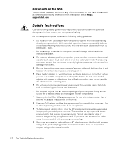
...ampere rating of the products plugged into the extension cable does not exceed the ampere rating of the extension cable. 1-2 Dell Latitude System Information With extended operation, heat can potentially build up in damage from potential damage and to help ensure proper grounding...Latitude portable computer to operate with papers or other container where metal objects (such as car keys) could cause discomfort or, eventually, a burn. • Do not attempt to service the computer yourself. Documents on the Web You can obtain the latest versions of any of the documents on your hard drive...
...ampere rating of the products plugged into the extension cable does not exceed the ampere rating of the extension cable. 1-2 Dell Latitude System Information With extended operation, heat can potentially build up in damage from potential damage and to help ensure proper grounding...Latitude portable computer to operate with papers or other container where metal objects (such as car keys) could cause discomfort or, eventually, a burn. • Do not attempt to service the computer yourself. Documents on the Web You can obtain the latest versions of any of the documents on your hard drive...


