Service Manual
Page 5
... Cover 1 7 Removing the Memory Modules 1 8 Replacing the Memory Modules 1 8 Mini PCI Card Assembly 1 9 Removing the Mini PCI Card Assembly 2 0 Replacing the Mini PCI Card Assembly 2 1 Keyboard Assembly 2 2 Removing the Keyboard Assembly 2 3 Replacing the...
... Cover 1 7 Removing the Memory Modules 1 8 Replacing the Memory Modules 1 8 Mini PCI Card Assembly 1 9 Removing the Mini PCI Card Assembly 2 0 Replacing the Mini PCI Card Assembly 2 1 Keyboard Assembly 2 2 Removing the Keyboard Assembly 2 3 Replacing the...

Service Manual
Page 13
....5 x 4 mm (1 each) Palmrest to Bottom Case Assembly: M2.5 x 20 mm (4 each ) B e fo r e You B e gi n 11 Screw Placement Map Hard Drive Door Security: M3.0 x 5 mm (1 each) Keyboard to Bottom Case Assembly: M2.5 x 20 mm (9 each) System Board: M2.5 x 4 mm captive washer (3 each) LED Board: M2.0 x 4 mm (2 each) Palmrest Bracket: M2.5 x 4 mm (2 each...
....5 x 4 mm (1 each) Palmrest to Bottom Case Assembly: M2.5 x 20 mm (4 each ) B e fo r e You B e gi n 11 Screw Placement Map Hard Drive Door Security: M3.0 x 5 mm (1 each) Keyboard to Bottom Case Assembly: M2.5 x 20 mm (9 each) System Board: M2.5 x 4 mm captive washer (3 each) LED Board: M2.0 x 4 mm (2 each) Palmrest Bracket: M2.5 x 4 mm (2 each...
Service Manual
Page 15
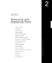
SECTION 2 Removing and Replacing Parts System Components Hard Drive Fixed Optical Drive Memory Module Mini PCI Card Assembly Keyboard Assembly Display and Bezel Assemblies Microprocessor Thermal Cooling Assembly Microprocessor Module Video Graphics Board Palmrest Assembly Reserve Battery System Board Assembly Battery and Modular Bay Latch Assemblies Battery Charger Board LED Board Fan Assembly RJ-11/RJ-45 Board www.dell.com | support.dell.com 2
SECTION 2 Removing and Replacing Parts System Components Hard Drive Fixed Optical Drive Memory Module Mini PCI Card Assembly Keyboard Assembly Display and Bezel Assemblies Microprocessor Thermal Cooling Assembly Microprocessor Module Video Graphics Board Palmrest Assembly Reserve Battery System Board Assembly Battery and Modular Bay Latch Assemblies Battery Charger Board LED Board Fan Assembly RJ-11/RJ-45 Board www.dell.com | support.dell.com 2

Service Manual
Page 16
com System Components Exploded View display assembly keyboard palmrest assembly hinge cover fixed optical drive modular device thermal cooling assembly system board hard drive 14 Rem o vi n g an d Rep l a ci n g Pa rt s bottom case assembly main battery d ell. w w w.d el l.co m | su p po rt.
com System Components Exploded View display assembly keyboard palmrest assembly hinge cover fixed optical drive modular device thermal cooling assembly system board hard drive 14 Rem o vi n g an d Rep l a ci n g Pa rt s bottom case assembly main battery d ell. w w w.d el l.co m | su p po rt.

Service Manual
Page 24
Keyboard Assembly NOTICE: Disconnect the computer and attached devices from electrical outlets and remove any installed batteries. NOTICE: To avoid ESD, ground yourself by using a wrist ...
Keyboard Assembly NOTICE: Disconnect the computer and attached devices from electrical outlets and remove any installed batteries. NOTICE: To avoid ESD, ground yourself by using a wrist ...

Service Manual
Page 25
Keyboard Screws 20-mm screws (4) Removing the Keyboard Assembly 1 Follow the instructions in "Preparing to pry up the keyboard. The keycaps are fragile, easily dislodged, and time-consuming to replace. 4 Use a nonmarring tool under the blank key to Work Inside the Computer." 2 Turn the computer over and remove the four screws labeled with a "circle K." 3 Turn the computer over and open the display. Re m ov i n g a nd Re p l ac i n g Pa rt s 23 NOTICE: Be careful when handling the keyboard.
Keyboard Screws 20-mm screws (4) Removing the Keyboard Assembly 1 Follow the instructions in "Preparing to pry up the keyboard. The keycaps are fragile, easily dislodged, and time-consuming to replace. 4 Use a nonmarring tool under the blank key to Work Inside the Computer." 2 Turn the computer over and remove the four screws labeled with a "circle K." 3 Turn the computer over and open the display. Re m ov i n g a nd Re p l ac i n g Pa rt s 23 NOTICE: Be careful when handling the keyboard.
Service Manual
Page 26
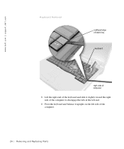
w w w.d el l.co m | su p po rt. d ell. com Keyboard Removal scalloped edge of blank key keyboard right side of computer 5 Lift the right end of the keyboard and slide it slightly toward the right side of the computer to disengage the tabs at the left end. 6 Pivot the keyboard and balance it upright on the left side of the computer. 24 Rem o vi n g an d Rep l a ci n g Pa rt s
w w w.d el l.co m | su p po rt. d ell. com Keyboard Removal scalloped edge of blank key keyboard right side of computer 5 Lift the right end of the keyboard and slide it slightly toward the right side of the computer to disengage the tabs at the left end. 6 Pivot the keyboard and balance it upright on the left side of the computer. 24 Rem o vi n g an d Rep l a ci n g Pa rt s

Service Manual
Page 27
... right surfaces of the bottom case assembly, and fit the keyboard into place. 3 Check that the keyboard is correctly installed. Keyboard Cable keyboard cable 7 Disconnect the keyboard cable and lay the keyboard assembly aside. NOTICE: Position the keyboard/track stick flex cable so it is not pinched when you...2 Insert the metal tabs at the left end, connect the keyboard cable to the interface connector on the system board. Replacing the Keyboard Assembly 1 While bracing the keyboard assembly upright on its left end of the keyboard under the edge of the palmrest. 4 Reinstall the four screws...
... right surfaces of the bottom case assembly, and fit the keyboard into place. 3 Check that the keyboard is correctly installed. Keyboard Cable keyboard cable 7 Disconnect the keyboard cable and lay the keyboard assembly aside. NOTICE: Position the keyboard/track stick flex cable so it is not pinched when you...2 Insert the metal tabs at the left end, connect the keyboard cable to the interface connector on the system board. Replacing the Keyboard Assembly 1 While bracing the keyboard assembly upright on its left end of the keyboard under the edge of the palmrest. 4 Reinstall the four screws...

Service Manual
Page 36
... microprocessor retaining clip microprocessor thermal cooling assembly Removing the Microprocessor Thermal Cooling Assembly 1 Follow the instructions in "Preparing to Work Inside the Computer." 2 Remove the keyboard. 3 Remove the hinge cover. 34 Rem o vi n g an d Rep l a ci n g Pa rt s d ell. w w w.d el l.co m | su p po rt...
... microprocessor retaining clip microprocessor thermal cooling assembly Removing the Microprocessor Thermal Cooling Assembly 1 Follow the instructions in "Preparing to Work Inside the Computer." 2 Remove the keyboard. 3 Remove the hinge cover. 34 Rem o vi n g an d Rep l a ci n g Pa rt s d ell. w w w.d el l.co m | su p po rt...

Service Manual
Page 38
... module straight up. NOTICE: To avoid damage to the microprocessor, hold the screwdriver so that it is perpendicular to Work Inside the Computer." 2 Remove the keyboard. 3 Remove the hinge cover. a Loosen the microprocessor socket cam lock screw. com Microprocessor Module Removing the Microprocessor Module 1 Follow the instructions in your skin reduce...
... module straight up. NOTICE: To avoid damage to the microprocessor, hold the screwdriver so that it is perpendicular to Work Inside the Computer." 2 Remove the keyboard. 3 Remove the hinge cover. a Loosen the microprocessor socket cam lock screw. com Microprocessor Module Removing the Microprocessor Module 1 Follow the instructions in your skin reduce...

Service Manual
Page 41
... rt s 39 NOTICE: To avoid ESD, ground yourself by using a wrist grounding strap or by periodically touching unpainted metal on the word "Dell" to Work Inside the Computer." 2 Remove the keyboard. 3 Remove the hinge cover. 4 Detach the display flex cable from the strain relief and the graphics card. 5 Remove the three 8-mm...
... rt s 39 NOTICE: To avoid ESD, ground yourself by using a wrist grounding strap or by periodically touching unpainted metal on the word "Dell" to Work Inside the Computer." 2 Remove the keyboard. 3 Remove the hinge cover. 4 Detach the display flex cable from the strain relief and the graphics card. 5 Remove the three 8-mm...

Service Manual
Page 43
Removing the Palmrest Assembly 1 Follow the instructions in "Preparing to the computer. NOTICE: To avoid damaging the palmrest assembly, you must first remove the display assembly. 6 Turn the computer over. 7 Remove the nine 20-mm screws (labeled with a "circle P") that secure the palmrest to Work Inside the Computer." 2 Remove the hard drive and the fixed optical drive. 3 Remove the keyboard. 4 Remove the hinge cover. 5 Remove the display assembly. Palmrest Screws 20-mm screw (9) Re m ov i n g a nd Re p l ac i n g Pa rt s 41
Removing the Palmrest Assembly 1 Follow the instructions in "Preparing to the computer. NOTICE: To avoid damaging the palmrest assembly, you must first remove the display assembly. 6 Turn the computer over. 7 Remove the nine 20-mm screws (labeled with a "circle P") that secure the palmrest to Work Inside the Computer." 2 Remove the hard drive and the fixed optical drive. 3 Remove the keyboard. 4 Remove the hinge cover. 5 Remove the display assembly. Palmrest Screws 20-mm screw (9) Re m ov i n g a nd Re p l ac i n g Pa rt s 41

Service Manual
Page 45
... the foam-pad remnants from the metal palmrest bracket. Removing the Reserve Battery 1 Follow the instructions in "Preparing to Work Inside the Computer." 2 Remove the keyboard. 3 Remove the hinge cover. 4 Remove the display assembly. 5 Remove the palmrest assembly. 6 On the underside of the palmrest, disconnect the flex cable from the ZIF...
... the foam-pad remnants from the metal palmrest bracket. Removing the Reserve Battery 1 Follow the instructions in "Preparing to Work Inside the Computer." 2 Remove the keyboard. 3 Remove the hinge cover. 4 Remove the display assembly. 5 Remove the palmrest assembly. 6 On the underside of the palmrest, disconnect the flex cable from the ZIF...

Service Manual
Page 48
... microprocessor, you must update the BIOS after replacing the microprocessor module. For instructions on updating or reflashing the BIOS, see the Dell Portable Computer BIOS Update Guide. com The replacement kit for the system board assembly includes a diskette or CD that provides a ...and the fixed optical drive. 3 Remove any installed Mini PCI Cards. 4 If migrating the memory, remove all installed memory modules. 5 Remove the keyboard. 6 Remove the hinge cover. 7 Remove the display assembly. 8 Remove the palmrest assembly. 9 Remove the video graphics board. 10 Remove the microprocessor...
... microprocessor, you must update the BIOS after replacing the microprocessor module. For instructions on updating or reflashing the BIOS, see the Dell Portable Computer BIOS Update Guide. com The replacement kit for the system board assembly includes a diskette or CD that provides a ...and the fixed optical drive. 3 Remove any installed Mini PCI Cards. 4 If migrating the memory, remove all installed memory modules. 5 Remove the keyboard. 6 Remove the hinge cover. 7 Remove the display assembly. 8 Remove the palmrest assembly. 9 Remove the video graphics board. 10 Remove the microprocessor...

Service Manual
Page 50
w w w.d el l.co m | su p po rt. com Battery and Modular Bay L atch Assemblies wear ribs (2 on underside) bumps slider spring location of snap tabs (2) latch buttons (2) bottom case assembly Removing and Replacing the Battery and Modular Bay Latch Assemblies 1 Follow the instructions in "Preparing to Work Inside the Computer." 2 Remove the keyboard. 3 Remove the hinge cover. 4 Remove the display assembly. 5 Remove the palmrest assembly. 48 Rem o vi n g an d Rep l a ci n g Pa rt s d ell.
w w w.d el l.co m | su p po rt. com Battery and Modular Bay L atch Assemblies wear ribs (2 on underside) bumps slider spring location of snap tabs (2) latch buttons (2) bottom case assembly Removing and Replacing the Battery and Modular Bay Latch Assemblies 1 Follow the instructions in "Preparing to Work Inside the Computer." 2 Remove the keyboard. 3 Remove the hinge cover. 4 Remove the display assembly. 5 Remove the palmrest assembly. 48 Rem o vi n g an d Rep l a ci n g Pa rt s d ell.

Service Manual
Page 52
... l a ci n g Pa rt s d ell. com Battery Charger Board Removing the Battery Charger Board 1 Follow the instructions in "Preparing to Work Inside the Computer." 2 Remove the keyboard. 3 Remove the hinge cover. 4 Remove the display assembly. 5 Remove the palmrest assembly. 6 Remove the video graphics board. 7 Lift the battery charger board out of the...
... l a ci n g Pa rt s d ell. com Battery Charger Board Removing the Battery Charger Board 1 Follow the instructions in "Preparing to Work Inside the Computer." 2 Remove the keyboard. 3 Remove the hinge cover. 4 Remove the display assembly. 5 Remove the palmrest assembly. 6 Remove the video graphics board. 7 Lift the battery charger board out of the...

Service Manual
Page 59
..., 32 palmrest, 43 H hard drive removing, 16 replacing, 16 hinge cover, 27 microprocessor thermal cooling assembly, 34 mini-PCI card assembly removing, 20 replacing, 21 K keyboard assembly removing, 23 replacing, 25 L latch assemblies, battery and modular bay, 47 LED board removing, 51 replacing, 52 M memory module removing modules, 1 8 removing the cover...
..., 32 palmrest, 43 H hard drive removing, 16 replacing, 16 hinge cover, 27 microprocessor thermal cooling assembly, 34 mini-PCI card assembly removing, 20 replacing, 21 K keyboard assembly removing, 23 replacing, 25 L latch assemblies, battery and modular bay, 47 LED board removing, 51 replacing, 52 M memory module removing modules, 1 8 removing the cover...
System Information Guide
Page 11
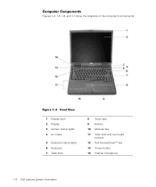
Computer Components Figures 1-4, 1-5, 1-6, and 1-7 show the locations of the computer's components. Front View 1 Display latch 2 Display 3 System status lights 4 Air intake 5 Keyboard status lights 6 Keyboard 7 Track stick 8 Touch pad 9 Battery 10 Modular bay 11 Track stick and touch pad buttons 12 Dell AccessDirect™ key 13 Power button 14 Internal microphone 1-8 Dell Latitude System Information Figure 1-4.
Computer Components Figures 1-4, 1-5, 1-6, and 1-7 show the locations of the computer's components. Front View 1 Display latch 2 Display 3 System status lights 4 Air intake 5 Keyboard status lights 6 Keyboard 7 Track stick 8 Touch pad 9 Battery 10 Modular bay 11 Track stick and touch pad buttons 12 Dell AccessDirect™ key 13 Power button 14 Internal microphone 1-8 Dell Latitude System Information Figure 1-4.
System Information Guide
Page 13
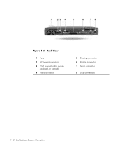
Back View 1 Fans 2 AC power connector 3 PS/2 connector (for mouse, keyboard, or keypad) 4 Video connector 5 Docking connector 6 Parallel connector 7 Serial connector 8 USB connectors 1-10 Dell Latitude System Information Figure 1-6.
Back View 1 Fans 2 AC power connector 3 PS/2 connector (for mouse, keyboard, or keypad) 4 Video connector 5 Docking connector 6 Parallel connector 7 Serial connector 8 USB connectors 1-10 Dell Latitude System Information Figure 1-6.


