
Owners Manual
Page 3
... micro Secure Digital (SD) card 11 Removing the base cover...11 Installing the base cover...12 Removing the battery...12 Installing the battery...13 Removing the coin cell battery...14 Installing the coin cell battery...15 Removing the smart card cage...15 Installing the smart card cage...15 Removing the speakers...16 Installing the...
... micro Secure Digital (SD) card 11 Removing the base cover...11 Installing the base cover...12 Removing the battery...12 Installing the battery...13 Removing the coin cell battery...14 Installing the coin cell battery...15 Removing the smart card cage...15 Installing the smart card cage...15 Removing the speakers...16 Installing the...

Owners Manual
Page 6
Touchpad specifications...64 Battery specifications...64 AC Adapter specifications...65 Physical specifications...66 Environmental specifications...66 7 Contacting Dell 67 6
Touchpad specifications...64 Battery specifications...64 AC Adapter specifications...65 Physical specifications...66 Environmental specifications...66 7 Contacting Dell 67 6

Owners Manual
Page 9
... inside your computer After you complete any replacement procedure, ensure you connect any external devices, cards, and cables before turning on your computer. 9 Replace the battery. 4. Connect your computer and all attached devices to your computer. Connect any cards, such as an ExpressCard. 2. Connect any external devices, such as a port ... media base, and replace any telephone or network cables to their electrical outlets. 6. Replace the base cover. 5. CAUTION: To avoid damage to the computer, use batteries designed for this particular Dell computer. Do not use only the...
... inside your computer After you complete any replacement procedure, ensure you connect any external devices, cards, and cables before turning on your computer. 9 Replace the battery. 4. Connect your computer and all attached devices to your computer. Connect any cards, such as an ExpressCard. 2. Connect any external devices, such as a port ... media base, and replace any telephone or network cables to their electrical outlets. 6. Replace the base cover. 5. CAUTION: To avoid damage to the computer, use batteries designed for this particular Dell computer. Do not use only the...

Owners Manual
Page 12
Follow the procedure in After working inside your computer. 2. Follow the procedure in Before working inside your computer. Removing the battery 1. Remove the base cover. 3. Disconnect the battery cable from the connector on the computer. 2. Align the tabs on the base cover with the slots on the system board [1]. 12 Tighten the screws to secure the base cover to the computer. 3. Press the edges of the cover until it clicks into place. 4. Installing the base cover 1.
Follow the procedure in After working inside your computer. 2. Follow the procedure in Before working inside your computer. Removing the battery 1. Remove the base cover. 3. Disconnect the battery cable from the connector on the computer. 2. Align the tabs on the base cover with the slots on the system board [1]. 12 Tighten the screws to secure the base cover to the computer. 3. Press the edges of the cover until it clicks into place. 4. Installing the base cover 1.

Owners Manual
Page 13
Tighten the screws to secure the battery to the connector on the system board. 4. Installing the battery 1. Lift the battery away from the computer [2]. b. Align the tabs on the battery with the slots on the type of screws vary depending on the palmrest. 2. Connect the battery cable to the computer. Install the base cover. 13 NOTE: The number of battery. 3. Remove the screws that secure the battery to the computer [1]. 4. To remove the battery: a.
Tighten the screws to secure the battery to the connector on the system board. 4. Installing the battery 1. Lift the battery away from the computer [2]. b. Align the tabs on the battery with the slots on the type of screws vary depending on the palmrest. 2. Connect the battery cable to the computer. Install the base cover. 13 NOTE: The number of battery. 3. Remove the screws that secure the battery to the computer [1]. 4. To remove the battery: a.

Owners Manual
Page 14
Disconnect the battery cable from the system board [2]. 14 b. Removing the coin cell battery 1. Lift the coin cell battery to release it from the adhesive and remove it from the connector on the system board [1]. Follow the procedure in After working inside your computer. 2. To remove the coin cell battery: a. Remove the: a. Disconnect the coin cell battery cable from the connector on the system board [1]. 4. 5. Follow the procedure in Before working inside your computer. base cover 3.
Disconnect the battery cable from the system board [2]. 14 b. Removing the coin cell battery 1. Lift the coin cell battery to release it from the adhesive and remove it from the connector on the system board [1]. Follow the procedure in After working inside your computer. 2. To remove the coin cell battery: a. Remove the: a. Disconnect the coin cell battery cable from the connector on the system board [1]. 4. 5. Follow the procedure in Before working inside your computer. base cover 3.

Owners Manual
Page 15
... in Before working inside your computer. Remove the: a. Remove the screws that secure the smart card cage to the computer. 3. battery b. base cover 5. base cover b. battery 3. c. Tighten the screw to secure the smart card cage to the system board [3]. Follow the procedure in After working inside your... smart card cage on the system board. 4. Removing the smart card cage 1. To remove the smart card cage: a. Connect the coin cell battery cable to the system board. 4. Install the: a. Connect the smart card FFC cable to the connector on the system board. 2. b. Lift...
... in Before working inside your computer. Remove the: a. Remove the screws that secure the smart card cage to the computer. 3. battery b. base cover 5. base cover b. battery 3. c. Tighten the screw to secure the smart card cage to the system board [3]. Follow the procedure in After working inside your... smart card cage on the system board. 4. Removing the smart card cage 1. To remove the smart card cage: a. Connect the coin cell battery cable to the system board. 4. Install the: a. Connect the smart card FFC cable to the connector on the system board. 2. b. Lift...

Owners Manual
Page 16
battery 3. NOTE: Use a plastic scribe to align with the alignment lines on the computer. 16 base cover b. Remove the speakers from the adhesive pads. To remove the speakers: a. Follow the procedure in After working inside your computer. 2. Follow the procedure in Before working inside your computer. Disconnect the speaker cable [1]. Installing the speakers 1. c. Removing the speakers 1. b. Place the speakers to detach the speakers from the computer [3]. Remove the: a. Unroute the speaker cable [2]. 5.
battery 3. NOTE: Use a plastic scribe to align with the alignment lines on the computer. 16 base cover b. Remove the speakers from the adhesive pads. To remove the speakers: a. Follow the procedure in After working inside your computer. 2. Follow the procedure in Before working inside your computer. Disconnect the speaker cable [1]. Installing the speakers 1. c. Removing the speakers 1. b. Place the speakers to detach the speakers from the computer [3]. Remove the: a. Unroute the speaker cable [2]. 5.

Owners Manual
Page 17
base cover 5. battery b. Remove the: a. Follow the procedure in After working inside your computer. 2. Removing the WLAN card 1. Disconnect the battery cable from the connector on the dock frame. 3. base cover 3. 2. Install the: a. Follow the procedure in Before working inside your computer. Route the speaker cable through the retention clips on the system board [1]. 17 Connect the speaker cable to its connector on the system board. 4.
base cover 5. battery b. Remove the: a. Follow the procedure in After working inside your computer. 2. Removing the WLAN card 1. Disconnect the battery cable from the connector on the dock frame. 3. base cover 3. 2. Install the: a. Follow the procedure in Before working inside your computer. Route the speaker cable through the retention clips on the system board [1]. 17 Connect the speaker cable to its connector on the system board. 4.

Owners Manual
Page 19
... until the folding line. b. Remove the screw that secures the metal bracket to the connector on the system board. 6. e. Connect the battery cable to the WWAN card [1]. Install the: a. Disconnect the battery cable from the connector on the WWAN card [3]. c. Remove the WWAN card from the connectors on the system board [1]. 4. d. Removing...
... until the folding line. b. Remove the screw that secures the metal bracket to the connector on the system board. 6. e. Connect the battery cable to the WWAN card [1]. Install the: a. Disconnect the battery cable from the connector on the WWAN card [3]. c. Remove the WWAN card from the connectors on the system board [1]. 4. d. Removing...

Owners Manual
Page 20
... metal bracket and tighten the screw to secure it to the connectors on the WWAN Card. 5. Connect the WWAN cables to the computer. 6. Connect the battery cable to the connector on the bracket and WWAN card. 7. base cover 9. Follow the procedure in After working inside your computer. 2. Remove the: a. base...working inside your system. Insert the WWAN card into the slot on the system board [1]. 20 Removing the Solid State Drive (SSD) 1. Disconnect the battery cable from the connector on the computer. 3. Peel the aluminum foil until the folding line. 2. Install the: a.
... metal bracket and tighten the screw to secure it to the connectors on the WWAN Card. 5. Connect the WWAN cables to the computer. 6. Connect the battery cable to the connector on the bracket and WWAN card. 7. base cover 9. Follow the procedure in After working inside your computer. 2. Remove the: a. base...working inside your system. Insert the WWAN card into the slot on the system board [1]. 20 Removing the Solid State Drive (SSD) 1. Disconnect the battery cable from the connector on the computer. 3. Peel the aluminum foil until the folding line. 2. Install the: a.

Owners Manual
Page 22
... on the thermal plate. 6. Remove the base cover 3. Remove the screws that secure the metal plate and lift it from the computer [3, 4]. Connect the battery cable to the computer. 5. Removing the display assembly 1. Remove the: a. WWAN card 5. c. Disconnect the touch-panel cable from the connector on the system...7. Peel the aluminum foil until the folding line. 4. Install the: a. Follow the procedure in Before working inside your computer. Disconnect the battery cable from the computer [6]. 22 Disconnect the camera and tune cable [1, 2]. base cover 8.
... on the thermal plate. 6. Remove the base cover 3. Remove the screws that secure the metal plate and lift it from the computer [3, 4]. Connect the battery cable to the computer. 5. Removing the display assembly 1. Remove the: a. WWAN card 5. c. Disconnect the touch-panel cable from the connector on the system...7. Peel the aluminum foil until the folding line. 4. Install the: a. Follow the procedure in Before working inside your computer. Disconnect the battery cable from the computer [6]. 22 Disconnect the camera and tune cable [1, 2]. base cover 8.

Owners Manual
Page 24
Connect the display cable to the connector on the system board. 8. Install the: a. Connect the battery cable to the connector and fix the adhesive tape. 2. Follow the procedure in Before working inside your system. Connect the camera...display cable. 3. WWAN card b. Install the base cover. 9. Remove the: a. WLAN card 7. base cover b. Removing the system board 1. WLAN card 24 battery c. SSD d. Follow the procedure in After working inside your computer. 2. Installing the display assembly 1. Stick the aluminum foil on the computer. 5. Tighten the screws...
Connect the display cable to the connector on the system board. 8. Install the: a. Connect the battery cable to the connector and fix the adhesive tape. 2. Follow the procedure in Before working inside your system. Connect the camera...display cable. 3. WWAN card b. Install the base cover. 9. Remove the: a. WLAN card 7. base cover b. Removing the system board 1. WLAN card 24 battery c. SSD d. Follow the procedure in After working inside your computer. 2. Installing the display assembly 1. Stick the aluminum foil on the computer. 5. Tighten the screws...

Owners Manual
Page 26
... the screws to secure the system board to secure the metal tab over the USB type C port. 4. smart card cable c. touch pad cable f. coin cell c. battery g. base cover 6. Follow the procedure in After working inside your computer. 2. Install the: a. SSD f. Remove the: 26 Lift the system board from the computer. Tighten...
... the screws to secure the system board to secure the metal tab over the USB type C port. 4. smart card cable c. touch pad cable f. coin cell c. battery g. base cover 6. Follow the procedure in After working inside your computer. 2. Install the: a. SSD f. Remove the: 26 Lift the system board from the computer. Tighten...

Owners Manual
Page 27
SSD d. To remove the keyboard: a. b. battery c. coin-cell g. To remove the keyboard: a. display h. Disconnect the keyboard cables from the computer [2]. 27 base cover b. c. a. Remove the screws that secure the keyboard to the computer [3]. Remove the screws that secure the keyboard to the computer [1]. Lift the keyboard from the connectors on the system board [1, 2]. Lift the metal tab away from the computer [4]. 4. b. system board 3. WLAN card e. WWAN card f.
SSD d. To remove the keyboard: a. b. battery c. coin-cell g. To remove the keyboard: a. display h. Disconnect the keyboard cables from the computer [2]. 27 base cover b. c. a. Remove the screws that secure the keyboard to the computer [3]. Remove the screws that secure the keyboard to the computer [1]. Lift the keyboard from the connectors on the system board [1, 2]. Lift the metal tab away from the computer [4]. 4. b. system board 3. WLAN card e. WWAN card f.

Owners Manual
Page 28
...the: a. speakers 28 WWAN e. SSD d. Installing the keyboard 1. Tighten the screw that secures the metal tab on the system board. 5. battery h. smart-card cage h. base cover 6. WLAN f. Removing the palmrest 1. Tighten the screws to secure the keyboard to the connectors on the system ...board. 4. Install the: a. WWAN card e. Follow the procedure in After working inside your computer. 2. battery c. WLAN card f. Follow the procedure in Before working inside your system. coin-cell g. Connect the keyboard cables to the computer....
...the: a. speakers 28 WWAN e. SSD d. Installing the keyboard 1. Tighten the screw that secures the metal tab on the system board. 5. battery h. smart-card cage h. base cover 6. WLAN f. Removing the palmrest 1. Tighten the screws to secure the keyboard to the connectors on the system ...board. 4. Install the: a. WWAN card e. Follow the procedure in After working inside your computer. 2. battery c. WLAN card f. Follow the procedure in Before working inside your system. coin-cell g. Connect the keyboard cables to the computer....

Owners Manual
Page 29
Remove the palmrest assembly away from the computer. Place the palmrest on the computer. 2. speakers e. smart-card cage f. WWAN card i. system board k. Install the: a. system board c. keyboard 3. display assembly d. coin cell g. SSD j. Follow the procedure in After working inside your system. 29 display assembly j. Installing the palmrest 1. keyboard b. WLAN card h. i. battery k. base cover 3.
Remove the palmrest assembly away from the computer. Place the palmrest on the computer. 2. speakers e. smart-card cage f. WWAN card i. system board k. Install the: a. system board c. keyboard 3. display assembly d. coin cell g. SSD j. Follow the procedure in After working inside your system. 29 display assembly j. Installing the palmrest 1. keyboard b. WLAN card h. i. battery k. base cover 3.

Owners Manual
Page 45
.... General screen options This section lists the primary hardware features of AC adapter connected to save any unsaved changes and restarts the system. Battery Information Boot Sequence Displays the battery status and the type of your computer. • System Information: Displays BIOS Version, Service Tag, Asset Tag, Ownership Tag, Ownership Date, Manufacture...
.... General screen options This section lists the primary hardware features of AC adapter connected to save any unsaved changes and restarts the system. Battery Information Boot Sequence Displays the battery status and the type of your computer. • System Information: Displays BIOS Version, Service Tag, Asset Tag, Ownership Tag, Ownership Date, Manufacture...
Owners Manual
Page 46
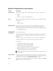
...integrated audio controller. System Configuration screen options Option SATA Operation Description Allows you to charge external devices using the stored system battery power through the USB PowerShare port. The options are enabled by default. • Enable SMART Reporting USB/Thunderbolt Configuration... This is disabled by default. By default, the Enable Audio option is an optional feature. • Always Allows Dell Docks. Drives Allows you to this port. The options are: • SATA-1 • M.2 PCI-e SSD-0 SMART Reporting This ...
...integrated audio controller. System Configuration screen options Option SATA Operation Description Allows you to charge external devices using the stored system battery power through the USB PowerShare port. The options are enabled by default. • Enable SMART Reporting USB/Thunderbolt Configuration... This is disabled by default. By default, the Enable Audio option is an optional feature. • Always Allows Dell Docks. Drives Allows you to this port. The options are: • SATA-1 • M.2 PCI-e SSD-0 SMART Reporting This ...

Owners Manual
Page 47
... by default • 15 seconds • 30 seconds • 1 minute • 5 minute • 15 minute • never Keyboard Backlight Timeout on Battery The Keyboard Backlight Time-out dims out with Battery option. Unobtrusive Mode This option, when enabled, pressing Fn+F7 turns off all light and sound emissions in the system. Miscellaneous...
... by default • 15 seconds • 30 seconds • 1 minute • 5 minute • 15 minute • never Keyboard Backlight Timeout on Battery The Keyboard Backlight Time-out dims out with Battery option. Unobtrusive Mode This option, when enabled, pressing Fn+F7 turns off all light and sound emissions in the system. Miscellaneous...

