Owners Manual
Page 2
...(SD) Card...9 Installing the Secure Digital (SD) Card...9 Removing the Battery...10 Installing the Battery...10 Removing the Base Cover...10 Installing the Base Cover...11 Removing the mSATA SSD Card...11 Installing the mSATA SSD Card...12 Removing the Memory...12 Installing the Memory...12 Removing...the TAA Board...14 Installing the TAA Board...14 Removing the System Fan...14 Installing the System Fan...15 Removing the Keyboard...15 Installing the Keyboard...17 Removing the Palmrest Assembly...17 Installing the Palmrest Assembly...19 Removing the Power-Switch Board...20 Installing the Power-...
...(SD) Card...9 Installing the Secure Digital (SD) Card...9 Removing the Battery...10 Installing the Battery...10 Removing the Base Cover...10 Installing the Base Cover...11 Removing the mSATA SSD Card...11 Installing the mSATA SSD Card...12 Removing the Memory...12 Installing the Memory...12 Removing...the TAA Board...14 Installing the TAA Board...14 Removing the System Fan...14 Installing the System Fan...15 Removing the Keyboard...15 Installing the Keyboard...17 Removing the Palmrest Assembly...17 Installing the Palmrest Assembly...19 Removing the Power-Switch Board...20 Installing the Power-...
Owners Manual
Page 15
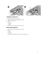
Installing the System Fan 1. Connect the system fan cable. 4. Removing the Keyboard 1. Follow the procedures in its slot on the computer. 2. Place the system fan in Before Working Inside Your Computer. 2. Tighten the screws that secure the system fan to the computer. 3. Follow the procedures in After Working Inside Your Computer. Disconnect the keyboard-backlight cable, trackstick cable, and keyboard cable. 15 Install: a) base cover b) SD card c) battery 5. Remove: a) battery b) SD card c) base cover 3.
Installing the System Fan 1. Connect the system fan cable. 4. Removing the Keyboard 1. Follow the procedures in its slot on the computer. 2. Place the system fan in Before Working Inside Your Computer. 2. Tighten the screws that secure the system fan to the computer. 3. Follow the procedures in After Working Inside Your Computer. Disconnect the keyboard-backlight cable, trackstick cable, and keyboard cable. 15 Install: a) base cover b) SD card c) battery 5. Remove: a) battery b) SD card c) base cover 3.
Owners Manual
Page 17
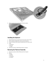
... in After Working Inside Your Computer. Installing the Keyboard 1. Remove: a) battery b) SD card c) base cover d) keyboard 17 Flip the computer and tighten the screws to secure the keyboard. 3. Removing the Palmrest Assembly 1. Install: a) base cover b) SD card c) battery 5. Flip the computer and remove the keyboard from the computer. Connect the keyboard cable, keyboard-backlight cable and trackstick cable. 4.
... in After Working Inside Your Computer. Installing the Keyboard 1. Remove: a) battery b) SD card c) base cover d) keyboard 17 Flip the computer and tighten the screws to secure the keyboard. 3. Removing the Palmrest Assembly 1. Install: a) base cover b) SD card c) battery 5. Flip the computer and remove the keyboard from the computer. Connect the keyboard cable, keyboard-backlight cable and trackstick cable. 4.
Owners Manual
Page 20
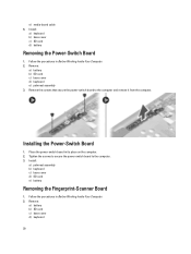
e) media-board cable 6. Remove: a) battery b) SD card c) base cover d) keyboard e) palmrest assembly 3. Tighten the screws to secure the power-switch board to the computer and remove it from the computer.... power-switch board to the computer. 3. Remove: a) battery b) SD card c) base cover d) keyboard 20 Install: a) keyboard b) base cover c) SD card d) battery Removing the Power-Switch Board 1. Installing the Power-Switch Board 1. Install: a) palmrest assembly b) keyboard c) base cover d) SD card e) battery Removing the Fingerprint-Scanner Board 1. Place the power-switch board ...
e) media-board cable 6. Remove: a) battery b) SD card c) base cover d) keyboard e) palmrest assembly 3. Tighten the screws to secure the power-switch board to the computer and remove it from the computer.... power-switch board to the computer. 3. Remove: a) battery b) SD card c) base cover d) keyboard 20 Install: a) keyboard b) base cover c) SD card d) battery Removing the Power-Switch Board 1. Installing the Power-Switch Board 1. Install: a) palmrest assembly b) keyboard c) base cover d) SD card e) battery Removing the Fingerprint-Scanner Board 1. Place the power-switch board ...
Owners Manual
Page 21
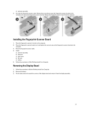
... fingerprint-scanner bracket to the computer and remove the fingerprint-scanner bracket. Remove the fingerpint-scanner board from the display assembly. 21 Install: a) palmrest assembly b) keyboard c) base cover d) SD card e) battery 5. Follow the procedures in its slot on it from the computer Installing the Fingerprint-Scanner Board 1. Removing the Display Bezel 1. Remove...
... fingerprint-scanner bracket to the computer and remove the fingerprint-scanner bracket. Remove the fingerpint-scanner board from the display assembly. 21 Install: a) palmrest assembly b) keyboard c) base cover d) SD card e) battery 5. Follow the procedures in its slot on it from the computer Installing the Fingerprint-Scanner Board 1. Removing the Display Bezel 1. Remove...
Owners Manual
Page 25
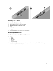
.... 25 Install: a) display bezel b) battery 5. Connect the LVDS and camera cable. 2. Follow the procedures in After Working Inside Your Computer. Remove: a) battery b) SD card c) base cover d) keyboard e) palmrest assembly 3. Follow the procedures in Before Working Inside Your Computer. 2. Remove the screws that secure the speakers to secure the camera module. 4. Place the...
.... 25 Install: a) display bezel b) battery 5. Connect the LVDS and camera cable. 2. Follow the procedures in After Working Inside Your Computer. Remove: a) battery b) SD card c) base cover d) keyboard e) palmrest assembly 3. Follow the procedures in Before Working Inside Your Computer. 2. Remove the screws that secure the speakers to secure the camera module. 4. Place the...
Owners Manual
Page 26
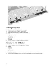
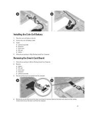
... Working Inside Your Computer. Disconnect the coin-cell battery cable. Tighten the screws that secure the speakers to the computer. 4. Remove: a) battery b) SD card c) base cover d) keyboard e) palmrest assembly 3. Install: a) palmrest assembly b) keyboard c) base cover d) SD card e) battery 5. Pry the coin-cell battery upward and remove it from the computer. 26
... Working Inside Your Computer. Disconnect the coin-cell battery cable. Tighten the screws that secure the speakers to the computer. 4. Remove: a) battery b) SD card c) base cover d) keyboard e) palmrest assembly 3. Install: a) palmrest assembly b) keyboard c) base cover d) SD card e) battery 5. Pry the coin-cell battery upward and remove it from the computer. 26
Owners Manual
Page 27
... remove the smart-card from the computer. 4. Place the coin-cell battery in its slot. 2. Removing the Smart-Card Board 1. Remove: a) battery b) SD card c) base cover d) keyboard e) palmrest assembly 3. Disconnect the smart-card cables from the computer. 27 Follow the procedures in Before Working Inside Your Computer. 2. Connect the coin-cell battery...
... remove the smart-card from the computer. 4. Place the coin-cell battery in its slot. 2. Removing the Smart-Card Board 1. Remove: a) battery b) SD card c) base cover d) keyboard e) palmrest assembly 3. Disconnect the smart-card cables from the computer. 27 Follow the procedures in Before Working Inside Your Computer. 2. Connect the coin-cell battery...
Owners Manual
Page 28
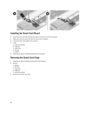
Connect the smart-card cables to the computer. 3. Remove: a) battery b) SD card c) base cover d) keyboard e) palmrest assembly 3. Install: a) palmrest assembly b) keyboard c) base cover d) SD card e) battery 5. Follow the procedures in After Working Inside Your Computer. Installing the Smart-Card Board 1. Disconnect the smart-card cable. 28 Removing the ...
Connect the smart-card cables to the computer. 3. Remove: a) battery b) SD card c) base cover d) keyboard e) palmrest assembly 3. Install: a) palmrest assembly b) keyboard c) base cover d) SD card e) battery 5. Follow the procedures in After Working Inside Your Computer. Installing the Smart-Card Board 1. Disconnect the smart-card cable. 28 Removing the ...
Owners Manual
Page 29
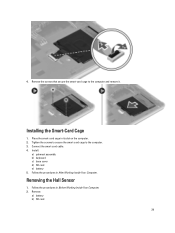
Tighten the screws to secure the smart-card cage to the computer and remove it. Follow the procedures in its slot on the computer. 2. Remove: a) battery b) SD card 29 Installing the Smart-Card Cage 1. Remove the screws that secure the smart-card cage to the computer. 3. Removing the Hall Sensor 1. Install: a) palmrest assembly b) keyboard c) base cover d) SD card e) battery 5. Connect the smart-card cable. 4. 4. Place the smart-card cage in Before Working Inside Your Computer. 2. Follow the procedures in After Working Inside Your Computer.
Tighten the screws to secure the smart-card cage to the computer and remove it. Follow the procedures in its slot on the computer. 2. Remove: a) battery b) SD card 29 Installing the Smart-Card Cage 1. Remove the screws that secure the smart-card cage to the computer. 3. Removing the Hall Sensor 1. Install: a) palmrest assembly b) keyboard c) base cover d) SD card e) battery 5. Connect the smart-card cable. 4. 4. Place the smart-card cage in Before Working Inside Your Computer. 2. Follow the procedures in After Working Inside Your Computer.
Owners Manual
Page 30
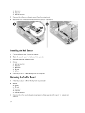
... the sniffer board to the computer and remove it . Place the hall sensor in Before Working Inside Your Computer. 2. Remove: a) palmrest assembly b) keyboard c) base cover d) SD card e) battery 5. c) base cover d) keyboard e) palmrest assembly 3. Disconnect the sniffer-board cable and remove the screw that secures the hall sensor to the computer. 3. Disconnect the hall-sensor...
... the sniffer board to the computer and remove it . Place the hall sensor in Before Working Inside Your Computer. 2. Remove: a) palmrest assembly b) keyboard c) base cover d) SD card e) battery 5. c) base cover d) keyboard e) palmrest assembly 3. Disconnect the sniffer-board cable and remove the screw that secures the hall sensor to the computer. 3. Disconnect the hall-sensor...
Owners Manual
Page 31
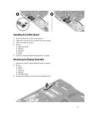
Place the sniffer board in After Working Inside Your Computer. Follow the procedures in its slot on the computer. 2. Remove: a) battery b) SD card c) base cover d) keyboard e) palmrest assembly 3. Remove: a) palmrest assembly b) keyboard c) base cover d) SD card e) battery 5. Installing the Sniffer Board 1. Tighten the screw that secures the sniffer board to the computer. 3. Follow the procedures in Before Working Inside Your Computer. 2. Removing the Display Assembly 1. Disconnect the LVDS and camera cable from the system board. 31 Connect the sniffer-board cable. 4.
Place the sniffer board in After Working Inside Your Computer. Follow the procedures in its slot on the computer. 2. Remove: a) battery b) SD card c) base cover d) keyboard e) palmrest assembly 3. Remove: a) palmrest assembly b) keyboard c) base cover d) SD card e) battery 5. Installing the Sniffer Board 1. Tighten the screw that secures the sniffer board to the computer. 3. Follow the procedures in Before Working Inside Your Computer. 2. Removing the Display Assembly 1. Disconnect the LVDS and camera cable from the system board. 31 Connect the sniffer-board cable. 4.
Owners Manual
Page 33
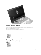
... 2. Follow the procedures in After Working Inside Your Computer. Place the display assembly onto the computer. 3. Install: a) palmrest assembly b) keyboard c) base cover d) SD card e) battery 8. Route the antenna and the LVDS cables through the holes on both sides to the wireless solution. 7. ...Remove: a) battery b) SD card c) base cover d) keyboard e) palmrest assembly 33 Connect the LVDS and camera cable to the computer. 6. Installing ...
... 2. Follow the procedures in After Working Inside Your Computer. Place the display assembly onto the computer. 3. Install: a) palmrest assembly b) keyboard c) base cover d) SD card e) battery 8. Route the antenna and the LVDS cables through the holes on both sides to the wireless solution. 7. ...Remove: a) battery b) SD card c) base cover d) keyboard e) palmrest assembly 33 Connect the LVDS and camera cable to the computer. 6. Installing ...
Owners Manual
Page 34
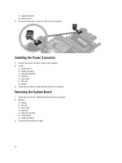
Installing the Power Connector 1. Connect the power-connector cable to the computer. 2. Remove: a) battery b) SD card c) base cover d) keyboard e) palmrest assembly f) sniffer board g) display assembly 3. Install: a) system board b) display assembly c) palmrest assembly d) keyboard e) base cover f) SD card g) battery 3. Follow the procedures in After Working Inside Your Computer. Follow the procedures in Before Working Inside Your...
Installing the Power Connector 1. Connect the power-connector cable to the computer. 2. Remove: a) battery b) SD card c) base cover d) keyboard e) palmrest assembly f) sniffer board g) display assembly 3. Install: a) system board b) display assembly c) palmrest assembly d) keyboard e) base cover f) SD card g) battery 3. Follow the procedures in After Working Inside Your Computer. Follow the procedures in Before Working Inside Your...
Owners Manual
Page 36
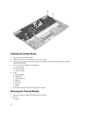
... the power-connector bracket to the system board: a) coin-cell battery b) hall-sensor cable c) smart-card cable 5. Install: a) display assembly b) sniffer board c) palmrest assembly d) keyboard e) base cover f) SD card g) battery 6. Follow the procedures in After Working Inside Your Computer. Tighten the screws to secure the system board to the computer. 3. Removing the...
... the power-connector bracket to the system board: a) coin-cell battery b) hall-sensor cable c) smart-card cable 5. Install: a) display assembly b) sniffer board c) palmrest assembly d) keyboard e) base cover f) SD card g) battery 6. Follow the procedures in After Working Inside Your Computer. Tighten the screws to secure the system board to the computer. 3. Removing the...
Owners Manual
Page 37
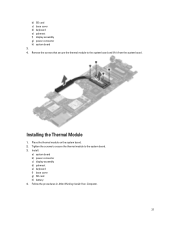
Tighten the screws to secure the thermal module to the system board and lift it from the system board. Follow the procedures in After Working Inside Your Computer. 37 Remove the screws that secure the thermal module to the system board. 3. b) SD card c) base cover d) keyboard e) palmrest f) display assembly g) power connector h) system board 3. 4. Place the thermal module on the system board. 2. Installing the Thermal Module 1. Install: a) system board b) power connector c) display assembly d) palmrest e) keyboard f) base cover g) SD card h) battery 4.
Tighten the screws to secure the thermal module to the system board and lift it from the system board. Follow the procedures in After Working Inside Your Computer. 37 Remove the screws that secure the thermal module to the system board. 3. b) SD card c) base cover d) keyboard e) palmrest f) display assembly g) power connector h) system board 3. 4. Place the thermal module on the system board. 2. Installing the Thermal Module 1. Install: a) system board b) power connector c) display assembly d) palmrest e) keyboard f) base cover g) SD card h) battery 4.
Owners Manual
Page 50
...Lock function is enabled. Code 1 Cause and Troubleshooting Steps BIOS ROM checksum in progress or failure System board failure, covers BIOS corruption or ROM error 2 No RAM detected No memory detected 3 Chipset Error (North and South Bridge Chipset,...) , Time-Of-Day Clock test failure , Gate A20 failure , Super I/O chip failure , Keyboard controller test failure System board failure 4 RAM Read/Write failure Memory failure 5 Real-time clock power fail CMOS battery failure 50...AC adapter present. Turns on An unauthenticated or unsupported non-Dell AC adapter is enabled.
...Lock function is enabled. Code 1 Cause and Troubleshooting Steps BIOS ROM checksum in progress or failure System board failure, covers BIOS corruption or ROM error 2 No RAM detected No memory detected 3 Chipset Error (North and South Bridge Chipset,...) , Time-Of-Day Clock test failure , Gate A20 failure , Super I/O chip failure , Keyboard controller test failure System board failure 4 RAM Read/Write failure Memory failure 5 Real-time clock power fail CMOS battery failure 50...AC adapter present. Turns on An unauthenticated or unsupported non-Dell AC adapter is enabled.
Owners Manual
Page 51
... LED codes are communicated via the Power Button LED. Code 1 Cause and Troubleshooting Steps System board: BIOS ROM failure System board failure, covers BIOS corruption or ROM error 2 Memory No memory/RAM detected 3 Chipset Error (North and South Bridge Chipset, DMA/IMR/ Timer Error)... , Time-Of-Day Clock test failure , Gate A20 failure , Super I/O chip failure , Keyboard controller test failure System board failure 4 RAM Read/Write failure Memory failure 5 Real-time clock power fail CMOS battery failure 6 Video BIOS test failure...
... LED codes are communicated via the Power Button LED. Code 1 Cause and Troubleshooting Steps System board: BIOS ROM failure System board failure, covers BIOS corruption or ROM error 2 Memory No memory/RAM detected 3 Chipset Error (North and South Bridge Chipset, DMA/IMR/ Timer Error)... , Time-Of-Day Clock test failure , Gate A20 failure , Super I/O chip failure , Keyboard controller test failure System board failure 4 RAM Read/Write failure Memory failure 5 Real-time clock power fail CMOS battery failure 6 Video BIOS test failure...


