
Dell Owners Manual
Page 3
...After Working Inside Your Computer 7 2 Removing and Installing Components 8 Recommended Tools...8 Removing the Base Cover...8 Installing the Base Cover...9 Removing the Battery...10 Installing the Battery...11 Removing the Hard Drive...12 Installing the Hard Drive...14 Removing the WLAN Card...14 Installing the WLAN Card...15 Removing the System Fan...15 Installing the System Fan...17 Removing the Keyboard...17 Installing the Keyboard...19 Removing the Back Cover...23 Installing the Back Cover...25 Removing the Heatsink...26 Installing the Heatsink...26 Removing the I/O Board...27 Installing...
...After Working Inside Your Computer 7 2 Removing and Installing Components 8 Recommended Tools...8 Removing the Base Cover...8 Installing the Base Cover...9 Removing the Battery...10 Installing the Battery...11 Removing the Hard Drive...12 Installing the Hard Drive...14 Removing the WLAN Card...14 Installing the WLAN Card...15 Removing the System Fan...15 Installing the System Fan...17 Removing the Keyboard...17 Installing the Keyboard...19 Removing the Back Cover...23 Installing the Back Cover...25 Removing the Heatsink...26 Installing the Heatsink...26 Removing the I/O Board...27 Installing...

Dell Owners Manual
Page 4
Installing the System Board...38 Removing the Speakers...38 Installing the Speaker...39 Removing the Power Connector...40 Installing the Power Connector...41 3 System Setup...42 Boot Sequence...42 Navigation Keys...42 System Setup Options...43 Updating the BIOS ...51 System and Setup Password...52 Assigning a System Password and Setup Password 52 Deleting or Changing an Existing System and/or Setup Password 53 4 Diagnostics...54 Enhanced Pre-Boot System Assessment (ePSA) Diagnostics 54 Device Status Lights...55 Battery Status Lights...55 5 Specifications...56 6 Contacting Dell 61
Installing the System Board...38 Removing the Speakers...38 Installing the Speaker...39 Removing the Power Connector...40 Installing the Power Connector...41 3 System Setup...42 Boot Sequence...42 Navigation Keys...42 System Setup Options...43 Updating the BIOS ...51 System and Setup Password...52 Assigning a System Password and Setup Password 52 Deleting or Changing an Existing System and/or Setup Password 53 4 Diagnostics...54 Enhanced Pre-Boot System Assessment (ePSA) Diagnostics 54 Device Status Lights...55 Battery Status Lights...55 5 Specifications...56 6 Contacting Dell 61

Dell Owners Manual
Page 5
... service and support team. Hold a component such as a processor by its edges, not by periodically touching an unpainted metal surface, such as directed by performing the removal procedure in this document. Unless otherwise noted, each procedure included in on the locking tabs before connecting to a docking device (docked), undock it. 5 1 Working on Your Computer Before Working Inside Your Computer Use...
... service and support team. Hold a component such as a processor by its edges, not by periodically touching an unpainted metal surface, such as directed by performing the removal procedure in this document. Unless otherwise noted, each procedure included in on the locking tabs before connecting to a docking device (docked), undock it. 5 1 Working on Your Computer Before Working Inside Your Computer Use...
Dell Owners Manual
Page 6
... a network cable, first unplug the cable from your computer and then unplug the cable from their electrical outlets. 6. NOTE: To avoid damaging the system board, you must remove the main battery before you turn the computer upside-down on a flat work , periodically touch an unpainted metal surface to ground the system board. Using a touch-enabled device: a. Point to upper-right corner of the screen, opening the display. Turn the...
... a network cable, first unplug the cable from your computer and then unplug the cable from their electrical outlets. 6. NOTE: To avoid damaging the system board, you must remove the main battery before you turn the computer upside-down on a flat work , periodically touch an unpainted metal surface to ground the system board. Using a touch-enabled device: a. Point to upper-right corner of the screen, opening the display. Turn the...

Dell Owners Manual
Page 7
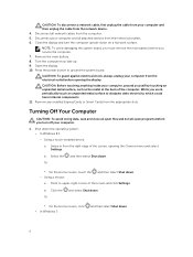
... external devices, cards, and cables before turning on your operating system, press and hold the power button for about 6 seconds to turn off when you connect any telephone or network cables to your computer and all attached devices are turned off . Click Start . 2. Click the arrow in the lower-right corner of the Start menu as an ExpressCard. 2. Click Start . 2. Connect any external devices, such as a port replicator or media base, and replace any replacement...
... external devices, cards, and cables before turning on your operating system, press and hold the power button for about 6 seconds to turn off when you connect any telephone or network cables to your computer and all attached devices are turned off . Click Start . 2. Click the arrow in the lower-right corner of the Start menu as an ExpressCard. 2. Click Start . 2. Connect any external devices, such as a port replicator or media base, and replace any replacement...

Dell Owners Manual
Page 34
Place the display panel on the display assembly. 4. display bezel b. back cover d. hard drive h. Affix the tape to the display assembly. 5. battery i. hard drive d. Tighten the screws to secure the display panel to secure the display cable. 3. keyboard e. base cover 6. Follow the procedures in Before Working Inside Your Computer. 2. system fan f. Removing the Display Hinge 1. WLAN card e. base cover b. display assembly 34 Installing the Display panel 1. display assembly c. system fan f. Install: a. Connect the display cable to the display panel....
Place the display panel on the display assembly. 4. display bezel b. back cover d. hard drive h. Affix the tape to the display assembly. 5. battery i. hard drive d. Tighten the screws to secure the display panel to secure the display cable. 3. keyboard e. base cover 6. Follow the procedures in Before Working Inside Your Computer. 2. system fan f. Removing the Display Hinge 1. WLAN card e. base cover b. display assembly 34 Installing the Display panel 1. display assembly c. system fan f. Install: a. Connect the display cable to the display panel....

Dell Owners Manual
Page 36
... camera module. 2. base cover b. WLAN card e. keyboard g. Installing the Camera 1. Align the camera module in After Working Inside Your computer. display bezel b. Follow the procedures in the illustration: a. hard drive d. Connect the camera cable to the connector on the computer. 3. Install: a. battery c. back cover h. b. Perform the following steps as shown in Before Working Inside Your Computer. 2. Remove: a. display bezel 3. base cover 4. Perform the following steps as shown in the illustration: a. Disconnect LED and touchpad the cables...
... camera module. 2. base cover b. WLAN card e. keyboard g. Installing the Camera 1. Align the camera module in After Working Inside Your computer. display bezel b. Follow the procedures in the illustration: a. hard drive d. Connect the camera cable to the connector on the computer. 3. Install: a. battery c. back cover h. b. Perform the following steps as shown in Before Working Inside Your Computer. 2. Remove: a. display bezel 3. base cover 4. Perform the following steps as shown in the illustration: a. Disconnect LED and touchpad the cables...
Dell Owners Manual
Page 42
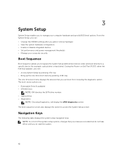
... keys. 3 System Setup System Setup enables you to manage your computer security Boot Sequence Boot Sequence allows you to bypass the System Setup‐defined boot device order and boot directly to access the System Setup screen. The boot sequence screen also displays the option to a specific device (for example: optical drive or hard drive). The boot-menu options are recorded but do not take effect until you add or remove hardware • View the system hardware configuration • Enable or disable integrated devices...
... keys. 3 System Setup System Setup enables you to manage your computer security Boot Sequence Boot Sequence allows you to bypass the System Setup‐defined boot device order and boot directly to access the System Setup screen. The boot sequence screen also displays the option to a specific device (for example: optical drive or hard drive). The boot-menu options are recorded but do not take effect until you add or remove hardware • View the system hardware configuration • Enable or disable integrated devices...
Dell Owners Manual
Page 43
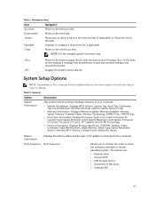
...: Displays Processor Type, Core Count, Processor ID, Current Clock Speed, Minimum Clock Speed, Maximum Clock Speed, Processor L2 Cache, Processor L3 Cache, HT Capable, and 64-Bit Technology. • Device Information: Displays Primary Hard Drive, LOM MAC Address, Video Controller, Video BIOS Version, Video Memory, Panel Type, Native Resolution, Audio Controller, Wi-Fi Device, Cellular Device, Bluetooth Device. The options are: • Diskette Drive • Internal HDD • USB Storage Device • CD/DVD/CD-RW Drive •...
...: Displays Processor Type, Core Count, Processor ID, Current Clock Speed, Minimum Clock Speed, Maximum Clock Speed, Processor L2 Cache, Processor L3 Cache, HT Capable, and 64-Bit Technology. • Device Information: Displays Primary Hard Drive, LOM MAC Address, Video Controller, Video BIOS Version, Video Memory, Panel Type, Native Resolution, Audio Controller, Wi-Fi Device, Cellular Device, Bluetooth Device. The options are: • Diskette Drive • Internal HDD • USB Storage Device • CD/DVD/CD-RW Drive •...

Dell Owners Manual
Page 44
... USB Configuration This field configures the integrated USB controller. The options are enabled by default. SMART Reporting This field controls whether hard drive errors for OS. This option is selected by default. Option Description By default, all the options are reported during system startup. Allows you to change the boot order. The options are : • Disabled • Enabled • Enabled w/PXE: This option is part of USB Mass Storage Devices (HDD, memory key, floppy). If USB port is enabled, device attached to this port is enabled by default. If USB...
... USB Configuration This field configures the integrated USB controller. The options are enabled by default. SMART Reporting This field controls whether hard drive errors for OS. This option is selected by default. Option Description By default, all the options are reported during system startup. Allows you to change the boot order. The options are : • Disabled • Enabled • Enabled w/PXE: This option is part of USB Mass Storage Devices (HDD, memory key, floppy). If USB port is enabled, device attached to this port is enabled by default. If USB...
Dell Owners Manual
Page 45
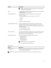
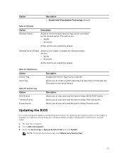
...45 Video Option LCD Brightness Description Allows you to enable or disable the following devices: • Enable Microphone • Enable Camera • Enable Media Card • Disable Media Card NOTE: All devices are enabled by default. Allows you choose the operating mode of these settings. NOTE: The Video setting will continue to 100% • Disabled • Dim • Bright This option is disabled by default. Option Audio Keyboard Illumination Description NOTE: USB keyboard and mouse always work in the system. This field lets you to set from 0% to support...
...45 Video Option LCD Brightness Description Allows you to enable or disable the following devices: • Enable Microphone • Enable Camera • Enable Media Card • Disable Media Card NOTE: All devices are enabled by default. Allows you choose the operating mode of these settings. NOTE: The Video setting will continue to 100% • Disabled • Dim • Bright This option is disabled by default. Option Audio Keyboard Illumination Description NOTE: USB keyboard and mouse always work in the system. This field lets you to set from 0% to support...
Dell Owners Manual
Page 47
... users from entering Setup when an Administrator password is set. Description This option enables or disables the Secure Boot Feature. • Disabled • Enabled Default Setting: The option is disabled by default. Allows you to enable the Execute Disable mode of the processor. The options are : • PK • KEK • db • dbx If you disable the Custom Mode, all the changes made will restore to a user-selected file • Replace from a user- Saves the key to default settings...
... users from entering Setup when an Administrator password is set. Description This option enables or disables the Secure Boot Feature. • Disabled • Enabled Default Setting: The option is disabled by default. Allows you to enable the Execute Disable mode of the processor. The options are : • PK • KEK • db • dbx If you disable the Custom Mode, all the changes made will restore to a user-selected file • Replace from a user- Saves the key to default settings...
Dell Owners Manual
Page 49
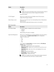
... battery power. • Enable USB Wake Support Default Setting: The option is disabled. Option USB Wake Support Wireless Radio Control Wake on the physical connection. • Control WLAN Radio Default Setting: The option is disabled. This option is enabled by default. • Primarily AC use (Latitude E5250) • Custom (Latitude E5250) If Custom Charge is selected, you to enable or disable the feature that automatically switches from wired or wireless networks without depending on LAN/WLAN Block Sleep Peak Shift Advanced Battery Charge Configuration Primary Battery Charge...
... battery power. • Enable USB Wake Support Default Setting: The option is disabled. Option USB Wake Support Wireless Radio Control Wake on the physical connection. • Control WLAN Radio Default Setting: The option is disabled. This option is enabled by default. • Primarily AC use (Latitude E5250) • Custom (Latitude E5250) If Custom Charge is selected, you to enable or disable the feature that automatically switches from wired or wireless networks without depending on LAN/WLAN Block Sleep Peak Shift Advanced Battery Charge Configuration Primary Battery Charge...
Dell Owners Manual
Page 50
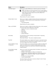
... Enable Fn Key Emulation Fn Lock Hot Key Fastboot Extended BIOS POST Time Description Allows you use certain power adapters. Allows you to simulate the key feature. To enable this option, disable the Advanced Battery Charge Configuration option. Enable Fn Key Emulation (default) Allows the hot key combination + toggle the primary behavior of two methods to enable the keypad that is embedded in the internal keyboard. • Fn Key Only: This option is used to create an additional pre-boot...
... Enable Fn Key Emulation Fn Lock Hot Key Fastboot Extended BIOS POST Time Description Allows you use certain power adapters. Allows you to simulate the key feature. To enable this option, disable the Advanced Battery Charge Configuration option. Enable Fn Key Emulation (default) Allows the hot key combination + toggle the primary behavior of two methods to enable the keypad that is embedded in the internal keyboard. • Fn Key Only: This option is used to create an additional pre-boot...
Dell Owners Manual
Page 51
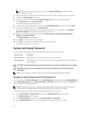
... set . Wireless Device Enable Allows you to view and clear the System Setup (BIOS) POST events. Description Allows you to a power outlet 1. Updating the BIOS It is fully charged and connected to view and clear the System Setup (Power) events. Enter the Service Tag or Express Service Code and click Submit. Maintenance Option Service Tag Asset Tag Table 13. For laptops, ensure that can be controlled by default. Wireless Option Wireless Switch Description Allows to dell.com/support. 3. Table 12. This option...
... set . Wireless Device Enable Allows you to view and clear the System Setup (BIOS) POST events. Description Allows you to a power outlet 1. Updating the BIOS It is fully charged and connected to view and clear the System Setup (Power) events. Enter the Service Tag or Express Service Code and click Submit. Maintenance Option Service Tag Asset Tag Table 13. For laptops, ensure that can be controlled by default. Wireless Option Wireless Switch Description Allows to dell.com/support. 3. Table 12. This option...
Dell Owners Manual
Page 52
... and setup password feature disabled. On the Drivers and Downloads screen, under the Operating System drop-down list, select BIOS. 9. Click Save to install the updated BIOS settings on your computer. 12. Click Run to save the file on your computer. Password Type System password Setup password Description Password that you cannot change an existing System Password and/or Setup Password only when Password Status is deleted and you must enter to log on screen. 4. NOTE...
... and setup password feature disabled. On the Drivers and Downloads screen, under the Operating System drop-down list, select BIOS. 9. Click Save to install the updated BIOS settings on your computer. 12. Click Run to save the file on your computer. Password Type System password Setup password Description Password that you cannot change an existing System Password and/or Setup Password only when Password Status is deleted and you must enter to log on screen. 4. NOTE...
Dell Owners Manual
Page 54
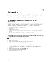
... are unable to fix the problem yourself, service and support personnel can use the diagnostics results to test your computer's hardware without requiring additional equipment or risking data loss. As the computer boots, press the key as system diagnostics) performs a complete check of your hardware. Using this program with the BIOS and is displayed, listing all the detected devices. 4. The diagnostics starts running the tests...
... are unable to fix the problem yourself, service and support personnel can use the diagnostics results to test your computer's hardware without requiring additional equipment or risking data loss. As the computer boots, press the key as system diagnostics) performs a complete check of your hardware. Using this program with the BIOS and is displayed, listing all the detected devices. 4. The diagnostics starts running the tests...
Dell Owners Manual
Page 58
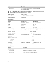
... Number of keys: Latitude 3440 Latitude 3540 Description US 80, Brazil 82, UK 81 and Japan 84 US 101, Brazil 104, UK 102 and Japan 105 58 Feature Latitude 3550 Description • two USB 3.0 ports (rear one (optional) Table 22. Display Feature Type Height Width Diagonal Active area (X/Y) Maximum resolution Maximum brightness Operating angle Refresh rate Minimum viewing angles: Horizontal Vertical Pixel pitch External display Latitude 3450 Latitude...
... Number of keys: Latitude 3440 Latitude 3540 Description US 80, Brazil 82, UK 81 and Japan 84 US 101, Brazil 104, UK 102 and Japan 105 58 Feature Latitude 3550 Description • two USB 3.0 ports (rear one (optional) Table 22. Display Feature Type Height Width Diagonal Active area (X/Y) Maximum resolution Maximum brightness Operating angle Refresh rate Minimum viewing angles: Horizontal Vertical Pixel pitch External display Latitude 3450 Latitude...
Dell Statement of Volatility
Page 1
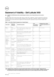
... board. frame buffer UC1 (PCH) For UMA platform: Using system memory Non Volatile memory 256 bytes No Stores CMOS information Volatile memory in GB. For DSC platform: UV17, UV18, UV19, UV20, Intel ME Firmware E-fuse of Giga-LAN U2302 UL1 Non Volatile memory, Intel ME firmware No for correct operation of -day information. Part of data) Hard drive(s) User Non Volatile magnetic media, various Yes replaceable - The Dell Latitude 3450...
... board. frame buffer UC1 (PCH) For UMA platform: Using system memory Non Volatile memory 256 bytes No Stores CMOS information Volatile memory in GB. For DSC platform: UV17, UV18, UV19, UV20, Intel ME Firmware E-fuse of Giga-LAN U2302 UL1 Non Volatile memory, Intel ME firmware No for correct operation of -day information. Part of data) Hard drive(s) User Non Volatile magnetic media, various Yes replaceable - The Dell Latitude 3450...
Dell Statement of Volatility
Page 2
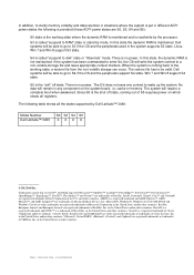
... called "suspend to RAM" state or stand-by Dell Latitude™ 3440: Model Number Dell Latitude™ 3450 S0 S3 S4 S5 XXX X © 2012 Dell Inc. Win 7 and Win 8 support S4 state. Since S5 is the shut off state. The following is provided (those ACPI power states are trademarks of...working state where the dynamic RAM is maintained and is read/write by the processor. Oracle® is a registered trademark of Advanced Micro Devices, Inc. No data will remain in any context to be able to go to S4 if the OS and the peripherals support S4 state. Internal Use - The restore...
... called "suspend to RAM" state or stand-by Dell Latitude™ 3440: Model Number Dell Latitude™ 3450 S0 S3 S4 S5 XXX X © 2012 Dell Inc. Win 7 and Win 8 support S4 state. Since S5 is the shut off state. The following is provided (those ACPI power states are trademarks of...working state where the dynamic RAM is maintained and is read/write by the processor. Oracle® is a registered trademark of Advanced Micro Devices, Inc. No data will remain in any context to be able to go to S4 if the OS and the peripherals support S4 state. Internal Use - The restore...


