
E-Family Re-Image Guide
Page 20
...driver Update (for ATAPI.SYS) o The Control Point Security Device Driver is available on Dell's driver & downloads support web site (support.dell.com) under Microsoft Windows Vista only Dell Latitude Ultrabook, E-Family & Mobile Precision Reimage "How-To" Guide 3. STMicroelectronics Trusted Platform Module... 1.1, 1.2 and 1.3. Dell Smart Card Keyboard 7. For Extended Battery Life feature (EBL), install the Dell Control Point components offered by Dell in case Control Point System Manager is available on Dell's driver & downloads support web site (support.dell.com) under Appendix-B for...
...driver Update (for ATAPI.SYS) o The Control Point Security Device Driver is available on Dell's driver & downloads support web site (support.dell.com) under Microsoft Windows Vista only Dell Latitude Ultrabook, E-Family & Mobile Precision Reimage "How-To" Guide 3. STMicroelectronics Trusted Platform Module... 1.1, 1.2 and 1.3. Dell Smart Card Keyboard 7. For Extended Battery Life feature (EBL), install the Dell Control Point components offered by Dell in case Control Point System Manager is available on Dell's driver & downloads support web site (support.dell.com) under Appendix-B for...
E-Family Re-Image Guide
Page 22
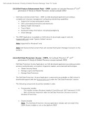
... Precision, except Latitude 3330) - DDPA, (for hot keys and system events Dell customized power plans and extensions Battery Health Information Touch Panel Keyboard hotkey information, including backlighting Smart Settings o The DFEP Application is a Dell developed application providing provides access to Latitude Precision 3rd & 4th generation E-Family & Mobile Precision, except Latitude 3330) o Dell Feature Enhancement...
... Precision, except Latitude 3330) - DDPA, (for hot keys and system events Dell customized power plans and extensions Battery Health Information Touch Panel Keyboard hotkey information, including backlighting Smart Settings o The DFEP Application is a Dell developed application providing provides access to Latitude Precision 3rd & 4th generation E-Family & Mobile Precision, except Latitude 3330) o Dell Feature Enhancement...
E-Family Re-Image Guide
Page 38
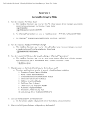
... After installing the drivers and you have this PCI yellow bang in device manager, you need to install the Control Point Security Device Driver Pack 3. Dell Latitude Ultrabook, E-Family & Mobile Precision Reimage "How-To" Guide Appendix C General Re-Imaging FAQs 1. a. After installing the drivers and you have this... a Broadcom USH Yellow Bang? a. The driver pack has the drivers for ATAPI.SYS) 5. Atmel Trusted Platform Module 3. Winbond Trusted Platform Module 5. Dell Smart Card Keyboard 7. Can I resolve this Unknown Device yellow bang on E-Family 2nd generation?
... After installing the drivers and you have this PCI yellow bang in device manager, you need to install the Control Point Security Device Driver Pack 3. Dell Latitude Ultrabook, E-Family & Mobile Precision Reimage "How-To" Guide Appendix C General Re-Imaging FAQs 1. a. After installing the drivers and you have this... a Broadcom USH Yellow Bang? a. The driver pack has the drivers for ATAPI.SYS) 5. Atmel Trusted Platform Module 3. Winbond Trusted Platform Module 5. Dell Smart Card Keyboard 7. Can I resolve this Unknown Device yellow bang on E-Family 2nd generation?
E-Family Re-Image Guide
Page 40
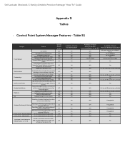
...settings Function Keys Hot Key customizaton Keyboard backlighting Brightness ALS Feature user profiles View battery manufacturer info. battery charge enable/disable status Network card power management Extended Battery Life/ All Day Battery Life. (ADBL) Dell Enhanced Performance Plans (User Selectable ...No screen pop-up display N/A No Yes N/A Yes, but with No screen pop-up display Yes N/A Yes, but No DCP App? Dell Latitude Ultrabook, E-Family & Mobile Precision Reimage "How-To" Guide Appendix D Tables - Discreet Graphics Fn+E to toggle display by default). Control ...
...settings Function Keys Hot Key customizaton Keyboard backlighting Brightness ALS Feature user profiles View battery manufacturer info. battery charge enable/disable status Network card power management Extended Battery Life/ All Day Battery Life. (ADBL) Dell Enhanced Performance Plans (User Selectable ...No screen pop-up display N/A No Yes N/A Yes, but with No screen pop-up display Yes N/A Yes, but No DCP App? Dell Latitude Ultrabook, E-Family & Mobile Precision Reimage "How-To" Guide Appendix D Tables - Discreet Graphics Fn+E to toggle display by default). Control ...

Owner's Manual
Page 3
... the Display Bezel...13 Removing The Camera...13 Installing The Camera...13 Removing The Display Panel...13 Installing The Display Panel...14 Removing The Keyboard...15 Installing The Keyboard...16 Removing The Palmrest...16 Installing The Palmrest...17 Removing The Wireless Local Area Network (WLAN) Card 18 Installing The Wireless Local Area...
... the Display Bezel...13 Removing The Camera...13 Installing The Camera...13 Removing The Display Panel...13 Installing The Display Panel...14 Removing The Keyboard...15 Installing The Keyboard...16 Removing The Palmrest...16 Installing The Palmrest...17 Removing The Wireless Local Area Network (WLAN) Card 18 Installing The Wireless Local Area...
Owner's Manual
Page 14
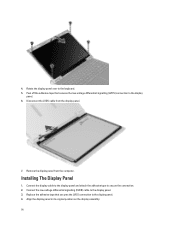
... the display panel. 7. Disconnect the LVDS cable from the computer. Replace the adhesive tape that secures the low-voltage differential signalling (LVDS) connection to the keyboard. 5. Connect the display cable to the display panel and attach the adhesive tape to the display panel. 4. Rotate the display panel over to the display...
... the display panel. 7. Disconnect the LVDS cable from the computer. Replace the adhesive tape that secures the low-voltage differential signalling (LVDS) connection to the keyboard. 5. Connect the display cable to the display panel and attach the adhesive tape to the display panel. 4. Rotate the display panel over to the display...
Owner's Manual
Page 15
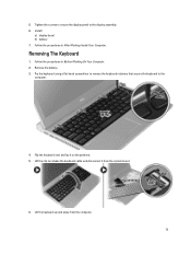
... from the computer. 15 Tighten the screws to secure the display panel to the computer. 4. Pry the keyboard using a flat-head screwdriver to remove the keyboard retainers that secure the keyboard to the display assembly. 6. Lift the keyboard up and away from the system board. 6. 5. Follow the procedures in After Working Inside Your Computer.
... from the computer. 15 Tighten the screws to secure the display panel to the computer. 4. Pry the keyboard using a flat-head screwdriver to remove the keyboard retainers that secure the keyboard to the display assembly. 6. Lift the keyboard up and away from the system board. 6. 5. Follow the procedures in After Working Inside Your Computer.

Owner's Manual
Page 16
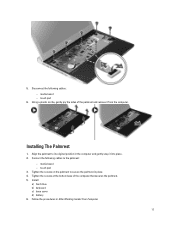
Remove: a) battery b) base cover c) keyboard d) hard drive 3. Remove the screws from the bottom of the computer, that secures the palmrest. 4. Remove the screws on the palmrest. 16 Insert the keyboard in After Working Inside Your Computer. Removing The Palmrest 1. Connect the keyboard cable to the system board. 2. Follow the procedures in its compartment. 3. Install the battery. 5. Follow the procedures in the computer. 4. Installing The Keyboard 1. Press down until the keyboard clicks into place in Before Working On Your Computer. 2.
Remove: a) battery b) base cover c) keyboard d) hard drive 3. Remove the screws from the bottom of the computer, that secures the palmrest. 4. Remove the screws on the palmrest. 16 Insert the keyboard in After Working Inside Your Computer. Removing The Palmrest 1. Connect the keyboard cable to the system board. 2. Follow the procedures in its compartment. 3. Install the battery. 5. Follow the procedures in the computer. 4. Installing The Keyboard 1. Press down until the keyboard clicks into place in Before Working On Your Computer. 2.
Owner's Manual
Page 17
... into place. 2. Disconnect the following cables to its original position in the computer and gently snap it from the computer. media board - Install: a) hard drive b) keyboard c) base cover d) battery 6. Follow the procedures in place. 4. Connect the following cables: - touch pad 6. media board - Tighten the screws on the palmrest to secure the...
... into place. 2. Disconnect the following cables to its original position in the computer and gently snap it from the computer. media board - Install: a) hard drive b) keyboard c) base cover d) battery 6. Follow the procedures in place. 4. Connect the following cables: - touch pad 6. media board - Tighten the screws on the palmrest to secure the...

Owner's Manual
Page 18
... the computer. 3. Follow the procedures in Before Working on Your Computer. 2. Remove: a) battery b) base cover c) hard drive d) keyboard e) palmrest 3. Disconnect the antenna cables from the computer base that secures the WLAN card. 5. Follow the procedures in Before Working on the ... on Your Computer. 2. Follow the procedures in After Working Inside Your Computer. Remove: a) battery b) base cover c) hard drive d) keyboard e) palmrest 3. Removing The Wireless Local Area Network (WLAN) Card 1. Removing The Display Assembly 1. Remove the screw that secures the display...
... the computer. 3. Follow the procedures in Before Working on Your Computer. 2. Remove: a) battery b) base cover c) hard drive d) keyboard e) palmrest 3. Disconnect the antenna cables from the computer base that secures the WLAN card. 5. Follow the procedures in Before Working on the ... on Your Computer. 2. Follow the procedures in After Working Inside Your Computer. Remove: a) battery b) base cover c) hard drive d) keyboard e) palmrest 3. Removing The Wireless Local Area Network (WLAN) Card 1. Removing The Display Assembly 1. Remove the screw that secures the display...
Owner's Manual
Page 21
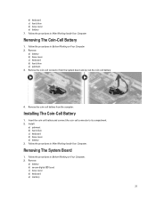
... Inside Your Computer Removing The Coin-Cell Battery 1. Remove: a) battery b) secure digital (SD) card c) base cover d) keyboard e) memory 21 Removing The System Board 1. Remove: a) battery b) base cover c) keyboard d) hard drive e) palmrest 3. Insert the coin-cell battery and connect the coin-cell connector to its compartment.... 2. b) keyboard c) hard drive d) base cover e) battery 7. Follow the procedures in Before Working on Your Computer 2. Follow the procedures in...
... Inside Your Computer Removing The Coin-Cell Battery 1. Remove: a) battery b) secure digital (SD) card c) base cover d) keyboard e) memory 21 Removing The System Board 1. Remove: a) battery b) base cover c) keyboard d) hard drive e) palmrest 3. Insert the coin-cell battery and connect the coin-cell connector to its compartment.... 2. b) keyboard c) hard drive d) base cover e) battery 7. Follow the procedures in Before Working on Your Computer 2. Follow the procedures in...
Owner's Manual
Page 22
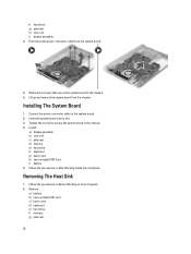
...The System Board 1. Insert the system board into its slot. 3. Remove: a) battery b) secure digital (SD) card c) base cover d) keyboard e) hard drive f) memory g) palmrest 22 Follow the procedures in Before Working on Your Computer. 2. Removing The Heat Sink 1. Disconnect the... power connector cable from the chassis. Install: a) display assembly b) coin-cell c) palmrest d) memory e) hard drive f) keyboard g) base cover h) secure digital (SD) Card i) battery 5. f) hard drive g) palmrest h) coin-cell i) display assembly 3. Lift up and remove ...
...The System Board 1. Insert the system board into its slot. 3. Remove: a) battery b) secure digital (SD) card c) base cover d) keyboard e) hard drive f) memory g) palmrest 22 Follow the procedures in Before Working on Your Computer. 2. Removing The Heat Sink 1. Disconnect the... power connector cable from the chassis. Install: a) display assembly b) coin-cell c) palmrest d) memory e) hard drive f) keyboard g) base cover h) secure digital (SD) Card i) battery 5. f) hard drive g) palmrest h) coin-cell i) display assembly 3. Lift up and remove ...
Owner's Manual
Page 23
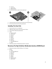
... heat sink from the system board. 4. Install: a) display assembly b) system board c) coin-cell d) palmrest e) memory f) hard drive g) keyboard h) base cover i) secure digital (SD) card j) battery 5. Remove: a) battery b) secure digital (SD) card c) base cover d) keyboard e) hard drive f) memory g) palmrest h) display assembly i) system board 23 Installing The Heat Sink 1. Connect the fan cable to...
... heat sink from the system board. 4. Install: a) display assembly b) system board c) coin-cell d) palmrest e) memory f) hard drive g) keyboard h) base cover i) secure digital (SD) card j) battery 5. Remove: a) battery b) secure digital (SD) card c) base cover d) keyboard e) hard drive f) memory g) palmrest h) display assembly i) system board 23 Installing The Heat Sink 1. Connect the fan cable to...
Owner's Manual
Page 24
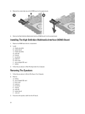
... The High-Definition Multimedia Interface (HDMI) Board 1. Replace the HDMI board into its compartment. 2. Install: a) display assembly b) system board c) display assembly d) palmrest e) memory f) hard drive g) keyboard h) base cover i) secure digital (SD) card j) battery 3. Remove the High-Definition Multimedia Interface (HDMI) board from the I/O board. 24 Removing The Speakers 1. 3. Disconnect the speaker...
... The High-Definition Multimedia Interface (HDMI) Board 1. Replace the HDMI board into its compartment. 2. Install: a) display assembly b) system board c) display assembly d) palmrest e) memory f) hard drive g) keyboard h) base cover i) secure digital (SD) card j) battery 3. Remove the High-Definition Multimedia Interface (HDMI) board from the I/O board. 24 Removing The Speakers 1. 3. Disconnect the speaker...
Owner's Manual
Page 25
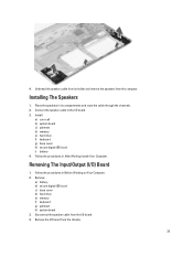
...holder and remove the speakers from the I /O) Board 1. Remove: a) battery b) secure digital (SD) card c) base cover d) hard drive e) memory f) keyboard g) palmrest h) system board 3. 4. Disconnect the speaker cable from the computer. Removing The Input/Output (I /O board. 4. Unthread the speaker cable from the... route the cable through the channels. 2. Install: a) coin-cell b) system board c) palmrest d) memory e) hard drive f) keyboard g) base cover h) secure digital (SD) card i) battery 4. Remove the I /O board. 3. Follow the procedures in Before Working on Your Computer. 2.
...holder and remove the speakers from the I /O) Board 1. Remove: a) battery b) secure digital (SD) card c) base cover d) hard drive e) memory f) keyboard g) palmrest h) system board 3. 4. Disconnect the speaker cable from the computer. Removing The Input/Output (I /O board. 4. Unthread the speaker cable from the... route the cable through the channels. 2. Install: a) coin-cell b) system board c) palmrest d) memory e) hard drive f) keyboard g) base cover h) secure digital (SD) card i) battery 4. Remove the I /O board. 3. Follow the procedures in Before Working on Your Computer. 2.
Owner's Manual
Page 26
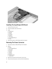
... up and remove the power connector port from the bottom base. 26 Install: a) system board b) palmrest c) memory d) hard drive e) keyboard f) base cover g) secure digital (SD) card h) battery 4. Removing The Power Connector 1. Remove: a) battery b) secure digital (SD) card c)... base cover d) hard drive e) palmrest f) memory g) keyboard h) display assembly i) system board 3. Insert the I /O) Board 1. Remove the screw that secures the power connector port. 4. Installing The Input/Output (I...
... up and remove the power connector port from the bottom base. 26 Install: a) system board b) palmrest c) memory d) hard drive e) keyboard f) base cover g) secure digital (SD) card h) battery 4. Removing The Power Connector 1. Remove: a) battery b) secure digital (SD) card c)... base cover d) hard drive e) palmrest f) memory g) keyboard h) display assembly i) system board 3. Insert the I /O) Board 1. Remove the screw that secures the power connector port. 4. Installing The Input/Output (I...
Owner's Manual
Page 27
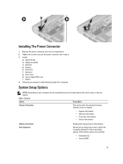
... not appear. Replace the power connector port into its installed devices, the items listed in place. 3. Install: a) system board b) display assembly c) palmrest d) memory e) hard drive f) keyboard g) base cover h) decure digital (SD) card i) battery 4. All the below options are selected. • Diskette Drive • Internal HDD 27 System Setup Options NOTE: Depending...
... not appear. Replace the power connector port into its installed devices, the items listed in place. 3. Install: a) system board b) display assembly c) palmrest d) memory e) hard drive f) keyboard g) base cover h) decure digital (SD) card i) battery 4. All the below options are selected. • Diskette Drive • Internal HDD 27 System Setup Options NOTE: Depending...

Owner's Manual
Page 30
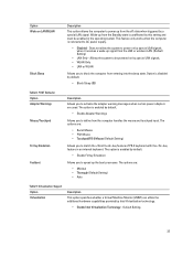
... an administrator password is set . The option is set . Option Password Bypass Password Change Non-Admin Setup Changes TPM Security Computrace CPU XD Support OROM Keyboard Access Admin Setup Lockout Description Allows you to enable or disable the permission to bypass the System and the Internal HDD password, when they are...
... an administrator password is set . The option is set . Option Password Bypass Password Change Non-Admin Setup Changes TPM Security Computrace CPU XD Support OROM Keyboard Access Admin Setup Lockout Description Allows you to enable or disable the permission to bypass the System and the Internal HDD password, when they are...
Owner's Manual
Page 33
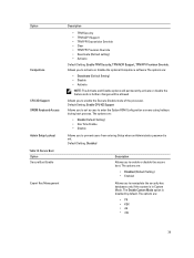
... enabled by default. • Enable Fn Key Emulation Allows you to match the key feature of PS-2 keyboard with the key feature in the operating system. Allows the system to be enabled in an internal keyboard. The option is connected to AC power supply. • Disabled - The option is disabled by default...
... enabled by default. • Enable Fn Key Emulation Allows you to match the key feature of PS-2 keyboard with the key feature in the operating system. Allows the system to be enabled in an internal keyboard. The option is connected to AC power supply. • Disabled - The option is disabled by default...
Owner's Manual
Page 39
... Setting) • Enabled Allows you to prevent users from entering Setup when an Administrator password is disabled by default. Option Computrace CPU XD Support OROM Keyboard Access Admin Setup Lockout Table 18. Allows you to enter the Option ROM Configuration screens using hotkeys during boot process. Default Setting: Enable CPU XD...
... Setting) • Enabled Allows you to prevent users from entering Setup when an Administrator password is disabled by default. Option Computrace CPU XD Support OROM Keyboard Access Admin Setup Lockout Table 18. Allows you to enter the Option ROM Configuration screens using hotkeys during boot process. Default Setting: Enable CPU XD...


