E-Family Re-Image Guide
Page 7
... touch support on Latitude E-Family & Mobile Precision 3rdgeneration. o Latitude On / Precision On - Latitude E-Family & Mobile Precision 4th generation o Intel® Responsiveness Technologies - Dell Latitude Ultrabook, E-Family & Mobile Precision Reimage "How-To" Guide o Dell Data Protection | Encryption(DDPE) - Reader, Flash, and ARM - Latitude E-Family & Mobile Precision 1st &2nd generation o WiDi display - Latitude E-Family & Mobile Precision 4th generation Latitude E-Family & Mobile Precision...
... touch support on Latitude E-Family & Mobile Precision 3rdgeneration. o Latitude On / Precision On - Latitude E-Family & Mobile Precision 4th generation o Intel® Responsiveness Technologies - Dell Latitude Ultrabook, E-Family & Mobile Precision Reimage "How-To" Guide o Dell Data Protection | Encryption(DDPE) - Reader, Flash, and ARM - Latitude E-Family & Mobile Precision 1st &2nd generation o WiDi display - Latitude E-Family & Mobile Precision 4th generation Latitude E-Family & Mobile Precision...

E-Family Re-Image Guide
Page 20
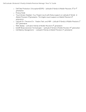
...Point" section 2.6.9.2 Control Point System Manager o Dell Control Point System Manager module is a Dell developed modular application providing a complete set of power management configuring and alerting capabilities: o Battery Status o Power Scheme and Sleep Mode o Display and Devices o Keyboard Backlighting and Hotkeys Customization... and Win7/8 32 & 64-Bit Note: Customers can obtain ALS feature by Dell in addition to Table B1 under "Control Point" section - Dell Latitude Ultrabook, E-Family & Mobile Precision Reimage "How-To" Guide 3. STMicroelectronics Trusted Platform Module 4.
...Point" section 2.6.9.2 Control Point System Manager o Dell Control Point System Manager module is a Dell developed modular application providing a complete set of power management configuring and alerting capabilities: o Battery Status o Power Scheme and Sleep Mode o Display and Devices o Keyboard Backlighting and Hotkeys Customization... and Win7/8 32 & 64-Bit Note: Customers can obtain ALS feature by Dell in addition to Table B1 under "Control Point" section - Dell Latitude Ultrabook, E-Family & Mobile Precision Reimage "How-To" Guide 3. STMicroelectronics Trusted Platform Module 4.
E-Family Re-Image Guide
Page 23
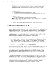
... Drivers Installer has already been installed on Dell's driver & downloads support web site (support.dell.com) under Appendix-B for WLAN controllers featured in Dell Latitude E-Family & Mobile Precision systems. To obtain wireless network functionality, install the Wireless LAN device driver applicable to Intel WLAN) functionality, install the Wireless Display Application found under the "Network" section...
... Drivers Installer has already been installed on Dell's driver & downloads support web site (support.dell.com) under Appendix-B for WLAN controllers featured in Dell Latitude E-Family & Mobile Precision systems. To obtain wireless network functionality, install the Wireless LAN device driver applicable to Intel WLAN) functionality, install the Wireless Display Application found under the "Network" section...
E-Family Re-Image Guide
Page 40
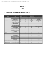
... (also Fn+D functionality which is set the intensity, inactivity timeout values and input triggers.) Ability to Adjust Brightness Level feedback through on screen display Ability to toggle display by default). Dell Latitude Ultrabook, E-Family & Mobile Precision Reimage "How-To" Guide Appendix D Tables - Control Point System Manager Features - Discreet Graphics Fn+E to enable/disable Privacy...
... (also Fn+D functionality which is set the intensity, inactivity timeout values and input triggers.) Ability to Adjust Brightness Level feedback through on screen display Ability to toggle display by default). Dell Latitude Ultrabook, E-Family & Mobile Precision Reimage "How-To" Guide Appendix D Tables - Control Point System Manager Features - Discreet Graphics Fn+E to enable/disable Privacy...

Owner's Manual
Page 3
... The Hard Drive...11 Installing The Hard Drive...12 Removing The Display Bezel...12 Installing the Display Bezel...13 Removing The Camera...13 Installing The Camera...13 Removing The Display Panel...13 Installing The Display Panel...14 Removing The Keyboard...15 Installing The Keyboard...16 Removing ...The Wireless Local Area Network (WLAN) Card 18 Installing The Wireless Local Area Network (WLAN) Card 18 Removing The Display Assembly...18 Installing The Display Assembly...20 Removing The Coin-Cell Battery...21 Installing The Coin-Cell Battery...21 Removing The System Board...21 Installing ...
... The Hard Drive...11 Installing The Hard Drive...12 Removing The Display Bezel...12 Installing the Display Bezel...13 Removing The Camera...13 Installing The Camera...13 Removing The Display Panel...13 Installing The Display Panel...14 Removing The Keyboard...15 Installing The Keyboard...16 Removing ...The Wireless Local Area Network (WLAN) Card 18 Installing The Wireless Local Area Network (WLAN) Card 18 Removing The Display Assembly...18 Installing The Display Assembly...20 Removing The Coin-Cell Battery...21 Installing The Coin-Cell Battery...21 Removing The System Board...21 Installing ...
Owner's Manual
Page 6
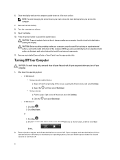
... remove the main battery before you work surface. Shut down . 1. b. If your computer from the right edge of the screen, opening the display. Turn the computer top-side up. 9. CAUTION: To guard against electrical shock, always unplug your computer and attached devices did not automatically turn off...as the metal at the back of the screen and click Settings. b. or 1. Open the display. 10. Click the arrow in from the electrical outlet before you shut down a. 6. Close the display and turn off your operating system, press and hold the power button for about 4 seconds to...
... remove the main battery before you work surface. Shut down . 1. b. If your computer from the right edge of the screen, opening the display. Turn the computer top-side up. 9. CAUTION: To guard against electrical shock, always unplug your computer and attached devices did not automatically turn off...as the metal at the back of the screen and click Settings. b. or 1. Open the display. 10. Click the arrow in from the electrical outlet before you shut down a. 6. Close the display and turn off your operating system, press and hold the power button for about 4 seconds to...
Owner's Manual
Page 12
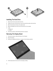
Install: a) base cover b) battery 6. Removing The Display Bezel 1. Follow the procedures in Before Working on Your Computer. 2. Remove the battery. 3. Replace and tighten the screw to secure the hard drive to the ... bay on the hard drive to secure the hard-drive bracket to the computer. 5. Lift the display bezel and remove it from the display assembly. 12 Gently pry the display bezel inside out to release it from the display assembly. 4. Tighten the screws on the system board. 4. Follow the procedures in After Working Inside...
Install: a) base cover b) battery 6. Removing The Display Bezel 1. Follow the procedures in Before Working on Your Computer. 2. Remove the battery. 3. Replace and tighten the screw to secure the hard drive to the ... bay on the hard drive to secure the hard-drive bracket to the computer. 5. Lift the display bezel and remove it from the display assembly. 12 Gently pry the display bezel inside out to release it from the display assembly. 4. Tighten the screws on the system board. 4. Follow the procedures in After Working Inside...

Owner's Manual
Page 13
...the camera to remove it snaps onto the display assembly. 3. Removing The Display Panel 1. Remove the screws that secure the display panel to the camera module. 3. Starting from the computer. Installing The Camera 1. Align the display bezel with the display assembly. 2. Follow the procedures in After...Working on Your Computer. 2. Connect the camera cable to the display assembly. 13 Follow the procedures in After Working Inside Your Computer. Remove: a) battery b) display bezel 3. Align the camera on the display bezel and work around the entire bezel until it from the top...
...the camera to remove it snaps onto the display assembly. 3. Removing The Display Panel 1. Remove the screws that secure the display panel to the camera module. 3. Starting from the computer. Installing The Camera 1. Align the display bezel with the display assembly. 2. Follow the procedures in After...Working on Your Computer. 2. Connect the camera cable to the display assembly. 13 Follow the procedures in After Working Inside Your Computer. Remove: a) battery b) display bezel 3. Align the camera on the display bezel and work around the entire bezel until it from the top...
Owner's Manual
Page 14
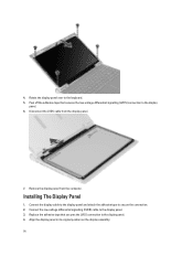
... (LVDS) cable to secure the connection. 2. Replace the adhesive tape that secures the low-voltage differential signalling (LVDS) connection to the display panel. 6. Remove the display panel from the display panel. 7. Rotate the display panel over to the display panel. 4. Peel off the adhesive tape that secures the LVDS connection to the keyboard. 5. Installing The...
... (LVDS) cable to secure the connection. 2. Replace the adhesive tape that secures the low-voltage differential signalling (LVDS) connection to the display panel. 6. Remove the display panel from the display panel. 7. Rotate the display panel over to the display panel. 4. Peel off the adhesive tape that secures the LVDS connection to the keyboard. 5. Installing The...
Owner's Manual
Page 15
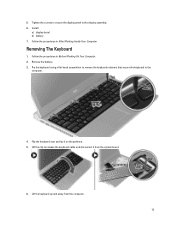
... on the palmrest. 5. Removing The Keyboard 1. Flip the keyboard over and lay it from the computer. 15 5. Tighten the screws to secure the display panel to the computer. 4. Install: a) display bezel b) battery 7. Remove the battery. 3. Pry the keyboard using a flat-head screwdriver to remove the keyboard retainers that secure the keyboard to...
... on the palmrest. 5. Removing The Keyboard 1. Flip the keyboard over and lay it from the computer. 15 5. Tighten the screws to secure the display panel to the computer. 4. Install: a) display bezel b) battery 7. Remove the battery. 3. Pry the keyboard using a flat-head screwdriver to remove the keyboard retainers that secure the keyboard to...

Owner's Manual
Page 18
.... 18 Insert the WLAN card into its connector. 2. Follow the procedures in Before Working on Your Computer. 2. Removing The Display Assembly 1. Remove: a) battery b) base cover c) hard drive d) keyboard e) palmrest 3. Disconnect the antenna cables from the computer base that secures the WLAN card. 5. Press the WLAN ...
.... 18 Insert the WLAN card into its connector. 2. Follow the procedures in Before Working on Your Computer. 2. Removing The Display Assembly 1. Remove: a) battery b) base cover c) hard drive d) keyboard e) palmrest 3. Disconnect the antenna cables from the computer base that secures the WLAN card. 5. Press the WLAN ...

Owner's Manual
Page 19
Disconnect the display cable from the computer and release it from the routing channel on the bottom base chassis. 5. Disconnect the WLAN cable and release the cable from the routing channel. 19 Turn over the computer. 4.
Disconnect the display cable from the computer and release it from the routing channel on the bottom base chassis. 5. Disconnect the WLAN cable and release the cable from the routing channel. 19 Turn over the computer. 4.

Owner's Manual
Page 20
Tighten the screws to secure the display assembly to the computer base. 2. Installing The Display Assembly 1. Carefully lift up the display assembly from the computer base. Tighten the screw to the connector on the system board. 5. Install: a) palmrest 20 6. Align the display assembly to the bottom base chassis. 4. Connect the display cable to secure the right hinge in the respective modules. 6. Route the WLAN cable in its routing channel and connect the cable in place. 3. Remove the screw that secures the right hinge. 7.
Tighten the screws to secure the display assembly to the computer base. 2. Installing The Display Assembly 1. Carefully lift up the display assembly from the computer base. Tighten the screw to the connector on the system board. 5. Install: a) palmrest 20 6. Align the display assembly to the bottom base chassis. 4. Connect the display cable to secure the right hinge in the respective modules. 6. Route the WLAN cable in its routing channel and connect the cable in place. 3. Remove the screw that secures the right hinge. 7.
Owner's Manual
Page 22
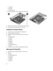
...The Heat Sink 1. Tighten the screws to secure the system board to the system board. 2. f) hard drive g) palmrest h) coin-cell i) display assembly 3. Lift up and remove the system board from the system board. 4. Remove: a) battery b) secure digital (SD) card c) base cover... d) keyboard e) hard drive f) memory g) palmrest 22 Installing The System Board 1. Install: a) display assembly b) coin-cell c) palmrest d) memory e) hard drive f) keyboard g) base cover h) secure digital (SD) Card i) battery 5. Disconnect the power connector...
...The Heat Sink 1. Tighten the screws to secure the system board to the system board. 2. f) hard drive g) palmrest h) coin-cell i) display assembly 3. Lift up and remove the system board from the system board. 4. Remove: a) battery b) secure digital (SD) card c) base cover... d) keyboard e) hard drive f) memory g) palmrest 22 Installing The System Board 1. Install: a) display assembly b) coin-cell c) palmrest d) memory e) hard drive f) keyboard g) base cover h) secure digital (SD) Card i) battery 5. Disconnect the power connector...
Owner's Manual
Page 23
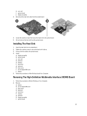
Install: a) display assembly b) system board c) coin-cell d) palmrest e) memory f) hard drive g) keyboard h) base cover i) secure digital (SD) card j) battery 5. Follow the procedures in Before Working on Your ... Your Computer. Lift and remove the heat sink from the system board. 4. Remove: a) battery b) secure digital (SD) card c) base cover d) keyboard e) hard drive f) memory g) palmrest h) display assembly i) system board 23 Disconnect the heat sink cable from the system board. Insert the heat sink into its compartment. 2. h) coin-cell i) system board...
Install: a) display assembly b) system board c) coin-cell d) palmrest e) memory f) hard drive g) keyboard h) base cover i) secure digital (SD) card j) battery 5. Follow the procedures in Before Working on Your ... Your Computer. Lift and remove the heat sink from the system board. 4. Remove: a) battery b) secure digital (SD) card c) base cover d) keyboard e) hard drive f) memory g) palmrest h) display assembly i) system board 23 Disconnect the heat sink cable from the system board. Insert the heat sink into its compartment. 2. h) coin-cell i) system board...
Owner's Manual
Page 24
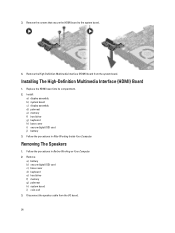
... c) base cover d) keyboard e) hard drive f) memory g) palmrest h) system board i) coin-cell 3. Remove the screws that secure the HDMI board to the system board. 4. Install: a) display assembly b) system board c) display assembly d) palmrest e) memory f) hard drive g) keyboard h) base cover i) secure digital (SD) card j) battery 3. Remove the High-Definition Multimedia Interface (HDMI) board from the...
... c) base cover d) keyboard e) hard drive f) memory g) palmrest h) system board i) coin-cell 3. Remove the screws that secure the HDMI board to the system board. 4. Install: a) display assembly b) system board c) display assembly d) palmrest e) memory f) hard drive g) keyboard h) base cover i) secure digital (SD) card j) battery 3. Remove the High-Definition Multimedia Interface (HDMI) board from the...
Owner's Manual
Page 26
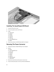
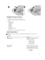
... secures the power connector port. 4. Insert the I /O board. 3. Removing The Power Connector 1. Remove: a) battery b) secure digital (SD) card c) base cover d) hard drive e) palmrest f) memory g) keyboard h) display assembly i) system board 3. Follow the procedures in After Working Inside Your Computer. Connect the speaker cable to the I /O board into its slot. 2. Lift up and...
... secures the power connector port. 4. Insert the I /O board. 3. Removing The Power Connector 1. Remove: a) battery b) secure digital (SD) card c) base cover d) hard drive e) palmrest f) memory g) keyboard h) display assembly i) system board 3. Follow the procedures in After Working Inside Your Computer. Connect the speaker cable to the I /O board into its slot. 2. Lift up and...
Owner's Manual
Page 27
...your computer. • System Information • Memory Information • Processor Information • Device Information Battery Information Boot Sequence Displays the charge status of the battery. All the below options are selected. • Diskette Drive • Internal HDD 27 Install: a) system... board b) display assembly c) palmrest d) memory e) hard drive f) keyboard g) base cover h) decure digital (SD) card i) battery 4. Table 1. Allows you ...
...your computer. • System Information • Memory Information • Processor Information • Device Information Battery Information Boot Sequence Displays the charge status of the battery. All the below options are selected. • Diskette Drive • Internal HDD 27 Install: a) system... board b) display assembly c) palmrest d) memory e) hard drive f) keyboard g) base cover h) decure digital (SD) card i) battery 4. Table 1. Allows you ...
Owner's Manual
Page 34
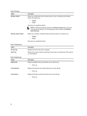
... by the wireless switch. The options are: • WWAN • WLAN All options are enabled by default. Description Displays the service tag of your computer. Maintenance Option Service Tag Asset Tag Table 12. Description Displays the BIOS event log and allows you to clear the log. • Clear Log... Displays the Thermal event log and allows you to clear the log. • Clear Log Displays the Power event log and allows you to clear the...
... by the wireless switch. The options are: • WWAN • WLAN All options are enabled by default. Description Displays the service tag of your computer. Maintenance Option Service Tag Asset Tag Table 12. Description Displays the BIOS event log and allows you to clear the log. • Clear Log... Displays the Thermal event log and allows you to clear the log. • Clear Log Displays the Power event log and allows you to clear the...

Owner's Manual
Page 35
...can : • Access System Setup by pressing key • Bring up the one-time boot menu by pressing key The one-time boot menu displays the devices that you make are : • Removable Drive (if available) • STXXXX Drive NOTE: XXX denotes the SATA drive number. •... a specific device (for example: optical drive or hard drive). Navigation Keys The following table displays the system setup navigation keys. Table 13. During the Power-on Self Test (POST), when the Dell logo appears, you can boot from including the diagnostic option. From the System Setup, you can...
...can : • Access System Setup by pressing key • Bring up the one-time boot menu by pressing key The one-time boot menu displays the devices that you make are : • Removable Drive (if available) • STXXXX Drive NOTE: XXX denotes the SATA drive number. •... a specific device (for example: optical drive or hard drive). Navigation Keys The following table displays the system setup navigation keys. Table 13. During the Power-on Self Test (POST), when the Dell logo appears, you can boot from including the diagnostic option. From the System Setup, you can...


