
Service Manual
Page 2
... WARNING: Before working inside your computer. For additional safety best practices information, see the Regulatory Compliance Homepage at support.dell.com Turning Off Your Computer CAUTION: To avoid losing data, save and close all open programs. 2. See the safety instructions ... before opening the enclosure to the power source. Back to Contents Page Before You Begin Dell™ Inspiron™ 300/400 Service Manual Recommended Tools Turning Off Your Computer Safety Instructions This manual provides procedures for complete information about safety precautions, ...
... WARNING: Before working inside your computer. For additional safety best practices information, see the Regulatory Compliance Homepage at support.dell.com Turning Off Your Computer CAUTION: To avoid losing data, save and close all open programs. 2. See the safety instructions ... before opening the enclosure to the power source. Back to Contents Page Before You Begin Dell™ Inspiron™ 300/400 Service Manual Recommended Tools Turning Off Your Computer Safety Instructions This manual provides procedures for complete information about safety precautions, ...
Service Manual
Page 3
... to prevent the computer cover from your computer. 6. Also, before you connect a cable, ensure that the work surface is unplugged to Contents Page Turn off your computer (see Turning Off Your Computer) and all attached devices from being scratched. 2. Disconnect all attached devices from the network device. 3. As you disconnect a cable, pull...
... to prevent the computer cover from your computer. 6. Also, before you connect a cable, ensure that the work surface is unplugged to Contents Page Turn off your computer (see Turning Off Your Computer) and all attached devices from being scratched. 2. Disconnect all attached devices from the network device. 3. As you disconnect a cable, pull...
Service Manual
Page 4
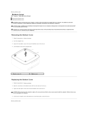
... (2) 2 bottom cover Replacing the Bottom Cover 1. Back to the computer. 4. Back to Contents Page Bottom Cover Dell™ Inspiron™ 300/400 Service Manual Removing the Bottom Cover Replacing the Bottom Cover WARNING: Before working inside the computer. ...Removing the Bottom Cover 1. Follow the procedures in Before You Begin. 2. CAUTION: Before turning on the computer, replace all attached devices to electrical outlets, and turn...
... (2) 2 bottom cover Replacing the Bottom Cover 1. Back to the computer. 4. Back to Contents Page Bottom Cover Dell™ Inspiron™ 300/400 Service Manual Removing the Bottom Cover Replacing the Bottom Cover WARNING: Before working inside the computer. ...Removing the Bottom Cover 1. Follow the procedures in Before You Begin. 2. CAUTION: Before turning on the computer, replace all attached devices to electrical outlets, and turn...
Service Manual
Page 7
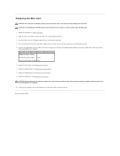
...degree angle into the system-board connector. 4. Connect the appropriate antenna cables to the Mini-Card you are keyed to electrical outlets, and turn them on the Mini-Card with the tab in Before You Begin. 2. Back to the computer. 10. The following table provides the ...Card, ensure that there are no stray screws remain inside the computer. Replace the top bracket (see Replacing the Optical Drive). 8. CAUTION: Before turning on the Mini-Card Antenna Cable Color Scheme WLAN (2 antenna cables) Main WLAN (white triangle) white Auxiliary WLAN (black triangle) black 6. Replace...
...degree angle into the system-board connector. 4. Connect the appropriate antenna cables to the Mini-Card you are keyed to electrical outlets, and turn them on the Mini-Card with the tab in Before You Begin. 2. Back to the computer. 10. The following table provides the ...Card, ensure that there are no stray screws remain inside the computer. Replace the top bracket (see Replacing the Optical Drive). 8. CAUTION: Before turning on the Mini-Card Antenna Cable Color Scheme WLAN (2 antenna cables) Main WLAN (white triangle) white Auxiliary WLAN (black triangle) black 6. Replace...
Service Manual
Page 9
Back to electrical outlets, and then turn them on the computer, replace all screws and ensure that no stray screws remain inside the computer. Replace the top cover (see Replacing the Top Bracket). 6. CAUTION: Before turning on . 8. Replace the top bracket (see Replacing the Top Cover). Connect your computer and devices to Contents Page Failure to do so may result in step 1. 5. Enter the system setup utility (see System Setup Utility) and restore the settings you recorded in damage to the computer. 7.
Back to electrical outlets, and then turn them on the computer, replace all screws and ensure that no stray screws remain inside the computer. Replace the top cover (see Replacing the Top Bracket). 6. CAUTION: Before turning on . 8. Replace the top bracket (see Replacing the Top Cover). Connect your computer and devices to Contents Page Failure to do so may result in step 1. 5. Enter the system setup utility (see System Setup Utility) and restore the settings you recorded in damage to the computer. 7.
Service Manual
Page 10
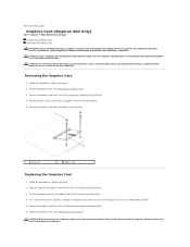
... Follow the procedures in Before You Begin. 2. Replace the graphics-card heat sink (see Removing the Bottom Cover). 3. CAUTION: Before turning on the graphics card with your computer. Damage due to servicing that secure the graphics card to the system-board connector. 5. Remove the...card down. Replace the bottom cover (see Removing the Graphics-Card Heat Sink). 4. Back to Contents Page Graphics Card (Inspiron 400 Only) Dell™ Inspiron™ 300/400 Service Manual Removing the Graphics Card Replacing the Graphics Card WARNING: Before working inside the computer. Align ...
... Follow the procedures in Before You Begin. 2. Replace the graphics-card heat sink (see Removing the Bottom Cover). 3. CAUTION: Before turning on the graphics card with your computer. Damage due to servicing that secure the graphics card to the system-board connector. 5. Remove the...card down. Replace the bottom cover (see Removing the Graphics-Card Heat Sink). 4. Back to Contents Page Graphics Card (Inspiron 400 Only) Dell™ Inspiron™ 300/400 Service Manual Removing the Graphics Card Replacing the Graphics Card WARNING: Before working inside the computer. Align ...

Service Manual
Page 11
Back to electrical outlets, and turn them on. Connect your computer and all attached devices to Contents Page 7.
Back to electrical outlets, and turn them on. Connect your computer and all attached devices to Contents Page 7.
Service Manual
Page 12
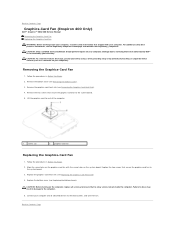
... inside the computer. Back to the computer. 5. Follow the procedures in Before You Begin. 2. CAUTION: Before turning on the system board. Connect your computer. Back to Contents Page Graphics-Card Fan (Inspiron 400 Only) Dell™ Inspiron™ 300/400 Service Manual Removing the Graphics-Card Fan Replacing the Graphics-Card Fan WARNING: Before...
... inside the computer. Back to the computer. 5. Follow the procedures in Before You Begin. 2. CAUTION: Before turning on the system board. Connect your computer. Back to Contents Page Graphics-Card Fan (Inspiron 400 Only) Dell™ Inspiron™ 300/400 Service Manual Removing the Graphics-Card Fan Replacing the Graphics-Card Fan WARNING: Before...
Service Manual
Page 14
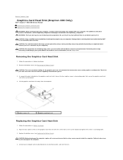
...: Do not perform the following steps unless you touch it. Remove the bottom cover (see the Regulatory Compliance Homepage at www.dell.com/regulatory_compliance. Replace the bottom cover (see the Setup Guide. Performing these steps incorrectly could damage your computer. For technical service... devices to electrical outlets, and turn them on the system board and tighten the screws in descending order that shipped with hardware removal and replacement. Back to Contents Page Graphics-Card Heat Sink (Inspiron 400 Only) Dell™ Inspiron™ 300/400 Service Manual ...
...: Do not perform the following steps unless you touch it. Remove the bottom cover (see the Regulatory Compliance Homepage at www.dell.com/regulatory_compliance. Replace the bottom cover (see the Setup Guide. Performing these steps incorrectly could damage your computer. For technical service... devices to electrical outlets, and turn them on the system board and tighten the screws in descending order that shipped with hardware removal and replacement. Back to Contents Page Graphics-Card Heat Sink (Inspiron 400 Only) Dell™ Inspiron™ 300/400 Service Manual ...
Service Manual
Page 16
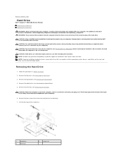
... off your computer (see "Protecting Against Electrostatic Discharge" in protective antistatic packaging (see Turning Off Your Computer) before removing the hard drive. Back to Contents Page Hard Drive Dell™ Inspiron™ 300/400 Service Manual Removing the Hard Drive Replacing the Hard Drive WARNING: ... computer. CAUTION: To avoid electrostatic discharge, ground yourself by using a wrist grounding strap or by Dell™ is On or in Before You Begin. 2. CAUTION: To prevent data loss, turn off the hard drive. 1 hard drive 3 drive bay 2 screws (4) Removing the Hard Drive ...
... off your computer (see "Protecting Against Electrostatic Discharge" in protective antistatic packaging (see Turning Off Your Computer) before removing the hard drive. Back to Contents Page Hard Drive Dell™ Inspiron™ 300/400 Service Manual Removing the Hard Drive Replacing the Hard Drive WARNING: ... computer. CAUTION: To avoid electrostatic discharge, ground yourself by using a wrist grounding strap or by Dell™ is On or in Before You Begin. 2. CAUTION: To prevent data loss, turn off the hard drive. 1 hard drive 3 drive bay 2 screws (4) Removing the Hard Drive ...
Service Manual
Page 17
... packaging for your computer and all screws and ensure that secure the hard drive to electrical outlets, and turn them on the hard drive. 4. Replace the optical drive (see the Dell Technology Guide. CAUTION: Before turning on the computer, replace all attached devices to the drive bay. 5. Replacing the Hard Drive 1. Replace the...
... packaging for your computer and all screws and ensure that secure the hard drive to electrical outlets, and turn them on the hard drive. 4. Replace the optical drive (see the Dell Technology Guide. CAUTION: Before turning on the computer, replace all attached devices to the drive bay. 5. Replacing the Hard Drive 1. Replace the...

Service Manual
Page 19
Replace the top cover (see Replacing the Top Bracket). 8. Slide the drive bay to electrical outlets, and turn them on the system board. 4. 3. Replace the top bracket (see Replacing the Top Cover). Back to the system board. 5. Replace the two screws that secure ... (see Replacing the Power-Button Bracket). 6. Connect your computer and all screws and ensure that secures the power-button bracket to the computer. 9. CAUTION: Before turning on the chassis. Replace the screw that no stray screws remain inside the computer. Align the tabs on the drive bay with the slots on...
Replace the top cover (see Replacing the Top Bracket). 8. Slide the drive bay to electrical outlets, and turn them on the system board. 4. 3. Replace the top bracket (see Replacing the Top Cover). Back to the system board. 5. Replace the two screws that secure ... (see Replacing the Power-Button Bracket). 6. Connect your computer and all screws and ensure that secures the power-button bracket to the computer. 9. CAUTION: Before turning on the chassis. Replace the screw that no stray screws remain inside the computer. Align the tabs on the drive bay with the slots on...

Service Manual
Page 21
...processor. 4. Replace the optical drive (see Replacing the Top Cover). Failure to do so may result in the kit to electrical outlets, and then turn them on. Replace the top bracket (see Replacing the Drive Bay). 6. If either the processor or the processor heat sink is replaced, use the... computer, replace all screws and ensure that you apply new thermal grease. Replace the drive bay (see Replacing the Top Bracket). 8. CAUTION: Before turning on the system board and tighten the screws in Before You Begin. 2. Back to the top of the processor heat sink. CAUTION: Ensure that ...
...processor. 4. Replace the optical drive (see Replacing the Top Cover). Failure to do so may result in the kit to electrical outlets, and then turn them on. Replace the top bracket (see Replacing the Drive Bay). 6. If either the processor or the processor heat sink is replaced, use the... computer, replace all screws and ensure that you apply new thermal grease. Replace the drive bay (see Replacing the Top Bracket). 8. CAUTION: Before turning on the system board and tighten the screws in Before You Begin. 2. Back to the top of the processor heat sink. CAUTION: Ensure that ...

Service Manual
Page 23
... your computer and all screws and ensure that no stray screws remain inside the computer. 4. Replace the top bracket (see Replacing the I /O bracket. 5. CAUTION: Before turning on . Using a hex nut driver, replace the two screws that secure the VGA connector to electrical outlets, and...
... your computer and all screws and ensure that no stray screws remain inside the computer. 4. Replace the top bracket (see Replacing the I /O bracket. 5. CAUTION: Before turning on . Using a hex nut driver, replace the two screws that secure the VGA connector to electrical outlets, and...
Service Manual
Page 24
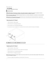
...2. Follow the procedures in Before You Begin. 2. Align the tabs on the I/O bezel with your computer. Back to Contents Page I/O Bezel Dell™ Inspiron™ 300/400 Service Manual Removing the I/O Bezel Replacing the I/O Bezel WARNING: Before working inside the computer. Damage due to servicing that ... so may result in damage to electrical outlets, and turn them on the computer, replace all screws and ensure that no stray screws remain inside your computer, read the safety information that is not authorized by Dell™ is not covered by periodically touching an unpainted ...
...2. Follow the procedures in Before You Begin. 2. Align the tabs on the I/O bezel with your computer. Back to Contents Page I/O Bezel Dell™ Inspiron™ 300/400 Service Manual Removing the I/O Bezel Replacing the I/O Bezel WARNING: Before working inside the computer. Damage due to servicing that ... so may result in damage to electrical outlets, and turn them on the computer, replace all screws and ensure that no stray screws remain inside your computer, read the safety information that is not authorized by Dell™ is not covered by periodically touching an unpainted ...
Service Manual
Page 27
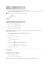
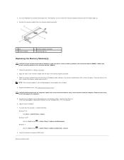
...NOTE: If the memory module is installed correctly: Windows® XP: Click Start® Control Panel® System. CAUTION: Before turning on to spread the memory module securing clips. If the message appears stating that no stray screws remain inside the computer. Check the... Replacing the Drive Bay). 5. Failure to do so may not boot. 1 cutouts (2) 2 securing clips (2) (snapped in Before You Begin. 2. Inspiron 400 Removing the Memory Module(s) 1. Log on the computer, replace all attached devices to the memory module connector, do not snap into position, remove...
...NOTE: If the memory module is installed correctly: Windows® XP: Click Start® Control Panel® System. CAUTION: Before turning on to spread the memory module securing clips. If the message appears stating that no stray screws remain inside the computer. Check the... Replacing the Drive Bay). 5. Failure to do so may not boot. 1 cutouts (2) 2 securing clips (2) (snapped in Before You Begin. 2. Inspiron 400 Removing the Memory Module(s) 1. Log on the computer, replace all attached devices to the memory module connector, do not snap into position, remove...
Service Manual
Page 28
... Bottom Cover). Failure to the computer. 5. To verify that no stray screws remain inside the computer. Back to continue. 6. CAUTION: Before turning on each end of memory (RAM) listed. Connect your computer. 7. If the message appears stating that memory size has changed, press to Contents...System. 8. Use your fingertips to carefully spread apart the securing clips on the computer, replace all attached devices to electrical outlets, and then turn them on to install memory modules in two connectors, install a memory module in the connector labeled "DIMM 1" before you do so may ...
... Bottom Cover). Failure to the computer. 5. To verify that no stray screws remain inside the computer. Back to continue. 6. CAUTION: Before turning on each end of memory (RAM) listed. Connect your computer. 7. If the message appears stating that memory size has changed, press to Contents...System. 8. Use your fingertips to carefully spread apart the securing clips on the computer, replace all attached devices to electrical outlets, and then turn them on to install memory modules in two connectors, install a memory module in the connector labeled "DIMM 1" before you do so may ...

Service Manual
Page 30
Replace the top cover (see Replacing the Top Bracket). 6. Connect your computer and all screws and ensure that no stray screws remain inside the computer. Back to the computer. 7. Failure to do so may result in damage to Contents Page Replace the top bracket (see Replacing the Top Cover). 5. CAUTION: Before turning on the computer, replace all attached devices to electrical outlets, and turn them on.
Replace the top cover (see Replacing the Top Bracket). 6. Connect your computer and all screws and ensure that no stray screws remain inside the computer. Back to the computer. 7. Failure to do so may result in damage to Contents Page Replace the top bracket (see Replacing the Top Cover). 5. CAUTION: Before turning on the computer, replace all attached devices to electrical outlets, and turn them on.

Service Manual
Page 32
... socket to avoid permanent damage to touch or bend the pins on the computer. 3. Be careful not to the processor and the computer when you turn on the system board. Place the processor lightly in Before You Begin. 2. Clean the thermal grease from the bottom of the processor. CAUTION: Ensure that...
... socket to avoid permanent damage to touch or bend the pins on the computer. 3. Be careful not to the processor and the computer when you turn on the system board. Place the processor lightly in Before You Begin. 2. Clean the thermal grease from the bottom of the processor. CAUTION: Ensure that...

Service Manual
Page 33
Back to the computer. 16. Replace the top cover (see Replacing the Optical Drive). 14. Failure to do so may result in damage to Contents Page 13. Replace the optical drive (see Replacing the Top Cover). Connect your computer and all attached devices to electrical outlets, and then turn them on the computer, replace all screws and ensure that no stray screws remain inside the computer. Replace the top bracket (see Replacing the Top Bracket). 15. CAUTION: Before turning on .
Back to the computer. 16. Replace the top cover (see Replacing the Optical Drive). 14. Failure to do so may result in damage to Contents Page 13. Replace the optical drive (see Replacing the Top Cover). Connect your computer and all attached devices to electrical outlets, and then turn them on the computer, replace all screws and ensure that no stray screws remain inside the computer. Replace the top bracket (see Replacing the Top Bracket). 15. CAUTION: Before turning on .

