Service Manual
Page 1
... 2002 Rev. A00 All rights reserved. Dell™ X200 Service Manual Before You Begin Preparing to Work Inside the Computer Recommended Tools Computer Orientation Screw Identification System Components Battery Memory Module and Mini PCI Card Memory Module Mini PCI Card Keyboard Palm Rest Hard Drive Hinge Covers and Display Assembly Hinge Covers Display Assembly Keyboard Tray Reserve Battery Speakers Cooling Fan System Board Modem Daughter Card Battery Latches Flashing the BIOS Pin Assignments for I/O Connectors Pin Assignments...
... 2002 Rev. A00 All rights reserved. Dell™ X200 Service Manual Before You Begin Preparing to Work Inside the Computer Recommended Tools Computer Orientation Screw Identification System Components Battery Memory Module and Mini PCI Card Memory Module Mini PCI Card Keyboard Palm Rest Hard Drive Hinge Covers and Display Assembly Hinge Covers Display Assembly Keyboard Tray Reserve Battery Speakers Cooling Fan System Board Modem Daughter Card Battery Latches Flashing the BIOS Pin Assignments for I/O Connectors Pin Assignments...
Service Manual
Page 2
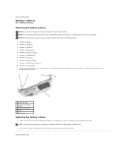
... newly installed latch moves smoothly and freely when pushed and released. Remove the battery. 2. Back to Contents Page Battery Latches Dell™ X200 Service Manual Removing the Battery Latches NOTICE: Disconnect the computer and any attached devices from the bottom case and the snap tabs, catching the latch button on the outside of the bottom case. 2. Remove the hinge covers. 5. Remove the system board. 11. Remove the memory module...
... newly installed latch moves smoothly and freely when pushed and released. Remove the battery. 2. Back to Contents Page Battery Latches Dell™ X200 Service Manual Removing the Battery Latches NOTICE: Disconnect the computer and any attached devices from the bottom case and the snap tabs, catching the latch button on the outside of the bottom case. 2. Remove the hinge covers. 5. Remove the system board. 11. Remove the memory module...
Service Manual
Page 3
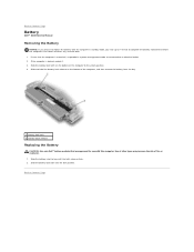
... use with the computer in a power management mode, or connected to the unlock position. 4. Slide the battery lock latch into the bay until the latch release clicks. 2. Use of other types may increase the risk of the computer, and then remove the battery from the bay. 1 battery lock latch 2 battery latch release Replacing the Battery CAUTION: Use only Dell™ battery modules that the computer is docked, undock it. 3. Slide the battery lock...
... use with the computer in a power management mode, or connected to the unlock position. 4. Slide the battery lock latch into the bay until the latch release clicks. 2. Use of other types may increase the risk of the computer, and then remove the battery from the bay. 1 battery lock latch 2 battery latch release Replacing the Battery CAUTION: Use only Dell™ battery modules that the computer is docked, undock it. 3. Slide the battery lock...
Service Manual
Page 4
... the system board, wait 10 to servicing that the computer is not covered by Dell is turned off the computer and all open programs. 3. Remove any work , use a wrist grounding strap or periodically touch an unpainted metal surface. 12. NOTICE: To avoid damaging the system board, you must remove the battery before you work in progress and exit all attached devices. Save any installed PC Cards or...
... the system board, wait 10 to servicing that the computer is not covered by Dell is turned off the computer and all open programs. 3. Remove any work , use a wrist grounding strap or periodically touch an unpainted metal surface. 12. NOTICE: To avoid damaging the system board, you must remove the battery before you work in progress and exit all attached devices. Save any installed PC Cards or...
Service Manual
Page 7
... to support.dell.com. Enter the service tag sequence for your first time to Contents Page Select the appropriate operating system and language for your computer. Click Go. 6. Select the FlashBIOS Updates download category. If this is your computer. 5. Click Go. 3. Click Downloads. 4. Go to Contents Page Flashing the BIOS Dell™ X200 Service Manual To update the basic input/output system (BIOS): 1. Back to use the...
... to support.dell.com. Enter the service tag sequence for your first time to Contents Page Select the appropriate operating system and language for your computer. Click Go. 6. Select the FlashBIOS Updates download category. If this is your computer. 5. Click Go. 3. Click Downloads. 4. Go to Contents Page Flashing the BIOS Dell™ X200 Service Manual To update the basic input/output system (BIOS): 1. Back to use the...
Service Manual
Page 8
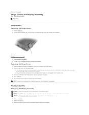
... a slot on the computer. Close the display. 5. Back to snap the hinge covers into place. 4. The left hinge cover fits over the power button and the right hinge cover fits over the display hinges: a. NOTE: The back of each hinge cover to Contents Page Hinge Covers and Display Assembly Dell™ X200 Service Manual Hinge Covers Display Assembly Hinge Covers Removing the Hinge Covers 1. Press down on the hinge covers to Work...
... a slot on the computer. Close the display. 5. Back to snap the hinge covers into place. 4. The left hinge cover fits over the power button and the right hinge cover fits over the display hinges: a. NOTE: The back of each hinge cover to Contents Page Hinge Covers and Display Assembly Dell™ X200 Service Manual Hinge Covers Display Assembly Hinge Covers Removing the Hinge Covers 1. Press down on the hinge covers to Work...

Service Manual
Page 11
... board connector 8. Remove the palm rest. 4. Remove the four M2 x 3-mm screws that secures the cooling fan cable to Contents Page Cooling Fan Dell™ X200 Service Manual Removing the Cooling Fan NOTICE: Disconnect the computer and any attached devices from the system board connector. 10. Disconnect the cooling fan cable from electrical outlets. Remove the keyboard tray. 7. Remove the keyboard. 3. Remove the hinge covers. 5. Remove the tape that secure the cooling fan to Work...
... board connector 8. Remove the palm rest. 4. Remove the four M2 x 3-mm screws that secures the cooling fan cable to Contents Page Cooling Fan Dell™ X200 Service Manual Removing the Cooling Fan NOTICE: Disconnect the computer and any attached devices from the system board connector. 10. Disconnect the cooling fan cable from electrical outlets. Remove the keyboard tray. 7. Remove the keyboard. 3. Remove the hinge covers. 5. Remove the tape that secure the cooling fan to Work...

Service Manual
Page 12
Remove the battery. 2. Disconnect the hard drive connector from electrical outlets. Back to Contents Page Hard Drive Dell™ X200 Service Manual Removing the Hard Drive NOTICE: Disconnect the computer and any attached devices from the system board. 6. Lift the hard drive up and out of the bottom case. Rubber grommets secure each screw to the hard drive so that secure the hard drive to completely remove the screws. Back to Work Inside the...
Remove the battery. 2. Disconnect the hard drive connector from electrical outlets. Back to Contents Page Hard Drive Dell™ X200 Service Manual Removing the Hard Drive NOTICE: Disconnect the computer and any attached devices from the system board. 6. Lift the hard drive up and out of the bottom case. Rubber grommets secure each screw to the hard drive so that secure the hard drive to completely remove the screws. Back to Work Inside the...

Service Manual
Page 13
... into the slot to replace. Back to Contents Page Keyboard Dell™ X200 Service Manual Removing the Keyboard NOTICE: Disconnect the computer and any attached devices from the bottom of the computer. 1 M2 x 4-mm screws (6) NOTICE: The keycaps on the computer. Be careful when removing and handling the keyboard. 3. consuming to the right of the keyboard locator tab. NOTICE: Read "Preparing to Work Inside the...
... into the slot to replace. Back to Contents Page Keyboard Dell™ X200 Service Manual Removing the Keyboard NOTICE: Disconnect the computer and any attached devices from the bottom of the computer. 1 M2 x 4-mm screws (6) NOTICE: The keycaps on the computer. Be careful when removing and handling the keyboard. 3. consuming to the right of the keyboard locator tab. NOTICE: Read "Preparing to Work Inside the...

Service Manual
Page 15
...the bottom case. 5. Press the keyboard flex cable into the ZIF connector on the system board, and do not reverse the keyboard flex cable. 2. Press the cable into the bottom case. 6. Ensure that the ZIF connector is open by pushing the ZIF connector tabs ...Replace the six M2 x 4-mm screws on the left and right keys to help control tab/slot alignment. Back to Contents Page To aid with the connection.) NOTICE: Position the keyboard flex cable so that the front edge of the keyboard is closed, which should not indicate a problem with proper flex cable connection, a blue locator...
...the bottom case. 5. Press the keyboard flex cable into the ZIF connector on the system board, and do not reverse the keyboard flex cable. 2. Press the cable into the bottom case. 6. Ensure that the ZIF connector is open by pushing the ZIF connector tabs ...Replace the six M2 x 4-mm screws on the left and right keys to help control tab/slot alignment. Back to Contents Page To aid with the connection.) NOTICE: Position the keyboard flex cable so that the front edge of the keyboard is closed, which should not indicate a problem with proper flex cable connection, a blue locator...
Service Manual
Page 16
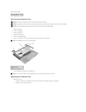
... Page Keyboard Tray Dell™ X200 Service Manual Removing the Keyboard Tray NOTICE: Disconnect the computer and any attached devices from electrical outlets. b. Slide the air vent into the bottom case. Remove the keyboard. 3. Lift the keyboard tray up and out of the computer comes loose when the keyboard tray is removed. Remove the display assembly. 6. Remove the battery. 2. NOTICE: To avoid ESD, ground yourself by using a wrist...
... Page Keyboard Tray Dell™ X200 Service Manual Removing the Keyboard Tray NOTICE: Disconnect the computer and any attached devices from electrical outlets. b. Slide the air vent into the bottom case. Remove the keyboard. 3. Lift the keyboard tray up and out of the computer comes loose when the keyboard tray is removed. Remove the display assembly. 6. Remove the battery. 2. NOTICE: To avoid ESD, ground yourself by using a wrist...
Service Manual
Page 18
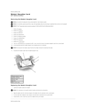
.... 4. Connect the modem cable to Work Inside the Computer" before performing the following procedure. 1. Use the screw hole to pull the modem daughter card straight up out of its connector on the system board. 3. Remove the keyboard. 3. do not force the connections. 2. Remove the hinge covers. 5. Remove the hard drive. 8. Remove the battery. 2. NOTICE: To avoid ESD, ground yourself by using a wrist grounding strap or by touching an...
.... 4. Connect the modem cable to Work Inside the Computer" before performing the following procedure. 1. Use the screw hole to pull the modem daughter card straight up out of its connector on the system board. 3. Remove the keyboard. 3. do not force the connections. 2. Remove the hinge covers. 5. Remove the hard drive. 8. Remove the battery. 2. NOTICE: To avoid ESD, ground yourself by using a wrist grounding strap or by touching an...
Service Manual
Page 20
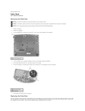
... should not indicate a problem with proper flex cable connection, a blue locator line has been added near the end of the computer. 1 M2 x 4-mm screws (4) 4. Back to Work Inside the Computer" before performing the following procedure. 1. NOTICE: Read "Preparing to Contents Page Palm Rest Dell™ X200 Service Manual Removing the Palm Rest NOTICE: Disconnect the computer and any attached devices from its...
... should not indicate a problem with proper flex cable connection, a blue locator line has been added near the end of the computer. 1 M2 x 4-mm screws (4) 4. Back to Work Inside the Computer" before performing the following procedure. 1. NOTICE: Read "Preparing to Contents Page Palm Rest Dell™ X200 Service Manual Removing the Palm Rest NOTICE: Disconnect the computer and any attached devices from its...
Service Manual
Page 27
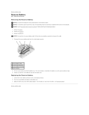
... Page Reserve Battery Dell™ X200 Service Manual Removing the Reserve Battery NOTICE: Disconnect the computer and any remnants of adhesive tape. 6. Remove the keyboard. 3. Pull from the reserve battery connector to the system board connector. 2. Connect the reserve battery connector to disconnect the cable. 4. Remove the battery. 2. The reserve battery is attached to flash the BIOS, see "Flashing the BIOS." Disconnect the reserve battery cable from the bottom case. Update the BIOS using a wrist grounding...
... Page Reserve Battery Dell™ X200 Service Manual Removing the Reserve Battery NOTICE: Disconnect the computer and any remnants of adhesive tape. 6. Remove the keyboard. 3. Pull from the reserve battery connector to the system board connector. 2. Connect the reserve battery connector to disconnect the cable. 4. Remove the battery. 2. The reserve battery is attached to flash the BIOS, see "Flashing the BIOS." Disconnect the reserve battery cable from the bottom case. Update the BIOS using a wrist grounding...
Service Manual
Page 28
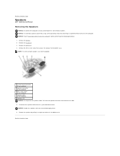
... the cable. 5. Pull from the speaker connector to the bottom case. Back to avoid damaging them. 6. Remove the battery. 2. NOTICE: Handle the speakers with care to Contents Page Speakers Dell™ X200 Service Manual Removing the Speakers NOTICE: Disconnect the computer and any attached devices from the system board connector. Remove the palm rest. 4. NOTICE: To avoid ESD, ground yourself by using...
... the cable. 5. Pull from the speaker connector to the bottom case. Back to avoid damaging them. 6. Remove the battery. 2. NOTICE: Handle the speakers with care to Contents Page Speakers Dell™ X200 Service Manual Removing the Speakers NOTICE: Disconnect the computer and any attached devices from the system board connector. Remove the palm rest. 4. NOTICE: To avoid ESD, ground yourself by using...
Service Manual
Page 29
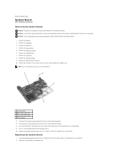
... light (LED) cable from the system board connector. 13. Remove the hinge covers. 5. Remove the memory module. 9. Disconnect the reserve battery connector from its ZIF connector on the computer. Lift the system board up and out of the bottom case. 15. Install the modem daughter card that secure the system board to Work Inside the Computer" before performing the following procedure. 1. Remove the hard drive. 8. Remove the battery. 2. Remove the display assembly. 6. Remove...
... light (LED) cable from the system board connector. 13. Remove the hinge covers. 5. Remove the memory module. 9. Disconnect the reserve battery connector from its ZIF connector on the computer. Lift the system board up and out of the bottom case. 15. Install the modem daughter card that secure the system board to Work Inside the Computer" before performing the following procedure. 1. Remove the hard drive. 8. Remove the battery. 2. Remove the display assembly. 6. Remove...
Service Manual
Page 31
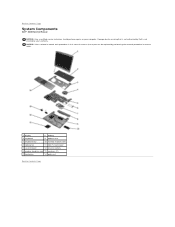
... perform repairs on your warranty. Back to servicing that a part can be replaced by your computer. NOTICE: Unless otherwise noted, each procedure in this manual assumes that is not authorized by Dell is not covered by performing the removal procedure in reverse order. 1 display 8 battery 2 keyboard 9 bottom case 3 keyboard tray 10 memory module cover 4 cooling fan 11 Mini PCI card cover 5 system board 12 reserve battery 6 modem daughter card 13 speakers (2) 7 hard drive 14...
... perform repairs on your warranty. Back to servicing that a part can be replaced by your computer. NOTICE: Unless otherwise noted, each procedure in this manual assumes that is not authorized by Dell is not covered by performing the removal procedure in reverse order. 1 display 8 battery 2 keyboard 9 bottom case 3 keyboard tray 10 memory module cover 4 cooling fan 11 Mini PCI card cover 5 system board 12 reserve battery 6 modem daughter card 13 speakers (2) 7 hard drive 14...
Service Manual
Page 32
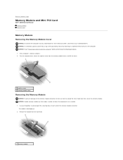
... Contents Page Memory Module and Mini PCI Card Dell™ X200 Service Manual Memory Module Mini PCI Card Memory Module Removing the Memory Module Cover NOTICE: Disconnect the computer and any attached devices from electrical outlets, and remove any installed batteries. NOTICE: Handle memory modules by touching an unpainted metal surface on the computer. Use your fingertips to spread apart the securing clips on a module. 1. Remove the module from the memory module cover, and lift the cover. 1 captive screw 2 memory module cover Removing the Memory Module NOTICE: To...
... Contents Page Memory Module and Mini PCI Card Dell™ X200 Service Manual Memory Module Mini PCI Card Memory Module Removing the Memory Module Cover NOTICE: Disconnect the computer and any attached devices from electrical outlets, and remove any installed batteries. NOTICE: Handle memory modules by touching an unpainted metal surface on the computer. Use your fingertips to spread apart the securing clips on a module. 1. Remove the module from the memory module cover, and lift the cover. 1 captive screw 2 memory module cover Removing the Memory Module NOTICE: To...

Service Manual
Page 33
..., or connect the AC adapter to close , remove the module and reinstall it . 2. Slide the edge of the connector. NOTICE: If the memory module cover is difficult to Work Inside the Computer" before performing the following procedure. 1. Turn on the computer. As the computer boots, it . 2 securing clips (2) Replacing the Memory Module 1. Ground yourself and install the new memory module: a. Forcing the cover to your computer. 1 captive screw 2 memory module cover...
..., or connect the AC adapter to close , remove the module and reinstall it . 2. Slide the edge of the connector. NOTICE: If the memory module cover is difficult to Work Inside the Computer" before performing the following procedure. 1. Turn on the computer. As the computer boots, it . 2 securing clips (2) Replacing the Memory Module 1. Ground yourself and install the new memory module: a. Forcing the cover to your computer. 1 captive screw 2 memory module cover...

Service Manual
Page 34
... the Mini PCI card until the card pops up slightly. 3. 1 captive screw 2 Mini PCI card cover Removing the Mini PCI Card 1. Replacing the Mini PCI Card 1. do not force the connections. 3. Back to approximately a 20-degree angle. 4. Release the Mini PCI card by spreading the metal securing tabs until it snaps into the connector. 2. NOTICE: The connectors are keyed for correct...
... the Mini PCI card until the card pops up slightly. 3. 1 captive screw 2 Mini PCI card cover Removing the Mini PCI Card 1. Replacing the Mini PCI Card 1. do not force the connections. 3. Back to approximately a 20-degree angle. 4. Release the Mini PCI card by spreading the metal securing tabs until it snaps into the connector. 2. NOTICE: The connectors are keyed for correct...


