Owner's Manual (PDF)
Page 5
11 VESA-Mount Bracket 43 Removing the VESA-Mount Bracket 43 Replacing the VESA-Mount Bracket 44 12 Hard Drive 45 Removing the Hard Drive 45 Replacing the Hard Drive 48 13 System-Board Shield 49 Removing the System-Board Shield 49 Replacing the System-Board Shield 51 14 TV Tuner Card 53 Removing the TV Tuner Card 53 Replacing the TV Tuner Card 56 15 Wireless Mini-Card 57 Removing the Wireless Mini-Card 57 Replacing the Wireless Mini-Card 59 Contents 5
11 VESA-Mount Bracket 43 Removing the VESA-Mount Bracket 43 Replacing the VESA-Mount Bracket 44 12 Hard Drive 45 Removing the Hard Drive 45 Replacing the Hard Drive 48 13 System-Board Shield 49 Removing the System-Board Shield 49 Replacing the System-Board Shield 51 14 TV Tuner Card 53 Removing the TV Tuner Card 53 Replacing the TV Tuner Card 56 15 Wireless Mini-Card 57 Removing the Wireless Mini-Card 57 Replacing the Wireless Mini-Card 59 Contents 5
Owner's Manual (PDF)
Page 43
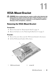
... that shipped with your computer, read the safety information that secure the VESA-mount bracket to the chassis. 2 Lift the VESA-mount bracket off the chassis. 2 1 1 VESA-mount bracket 2 screws (9) VESA-Mount Bracket 43 For additional safety best practices information, see the Regulatory Compliance Homepage at dell.com/regulatory_compliance. See "Removing the Back Cover" on page 19. 2 Remove the...
... that shipped with your computer, read the safety information that secure the VESA-mount bracket to the chassis. 2 Lift the VESA-mount bracket off the chassis. 2 1 1 VESA-mount bracket 2 screws (9) VESA-Mount Bracket 43 For additional safety best practices information, see the Regulatory Compliance Homepage at dell.com/regulatory_compliance. See "Removing the Back Cover" on page 19. 2 Remove the...

Owner's Manual (PDF)
Page 44
Replacing the VESA-Mount Bracket Procedure 1 Align the screw holes on the VESA-mount bracket with the screw holes on page 13. 44 VESA-Mount Bracket See "Replacing the Stand" on page 21. 3 Follow the instructions in "After Working Inside Your Computer" on the chassis. 2 Replace the screws that secure the VESA-mount bracket to the chassis. Postrequisites 1 Replace the back cover. See "Replacing the Back Cover" on page 24. 2 Replace the stand.
Replacing the VESA-Mount Bracket Procedure 1 Align the screw holes on the VESA-mount bracket with the screw holes on page 13. 44 VESA-Mount Bracket See "Replacing the Stand" on page 21. 3 Follow the instructions in "After Working Inside Your Computer" on the chassis. 2 Replace the screws that secure the VESA-mount bracket to the chassis. Postrequisites 1 Replace the back cover. See "Replacing the Back Cover" on page 24. 2 Replace the stand.
Owner's Manual (PDF)
Page 45
See "Removing the Stand" on page 23. 3 Remove the VESA-mount bracket. Exercise care when handling the hard drive. See "Removing the Back Cover" on page 19. 2 Remove the ... do not remove the hard drive while the computer is On or in "Before You Begin" on page 43. See "Removing the VESA-Mount Bracket" on page 11. Removing the Hard Drive Prerequisites 1 Remove the stand. CAUTION: Hard drives are extremely fragile. Hard Drive 45...the steps in Sleep state. For additional safety best practices information, see the Regulatory Compliance Homepage at dell.com/regulatory_compliance.
See "Removing the Stand" on page 23. 3 Remove the VESA-mount bracket. Exercise care when handling the hard drive. See "Removing the Back Cover" on page 19. 2 Remove the ... do not remove the hard drive while the computer is On or in "Before You Begin" on page 43. See "Removing the VESA-Mount Bracket" on page 11. Removing the Hard Drive Prerequisites 1 Remove the stand. CAUTION: Hard drives are extremely fragile. Hard Drive 45...the steps in Sleep state. For additional safety best practices information, see the Regulatory Compliance Homepage at dell.com/regulatory_compliance.
Owner's Manual (PDF)
Page 48
... screw holes on the hard drive. 3 Replace the screws that secure the hard-drive cage to the connector on the hard drive. See "Replacing the VESA-Mount Bracket" on page 13. 48 Hard Drive See "Replacing the Stand" on page 21. 4 Follow the instructions in "After Working Inside Your Computer" on page... cable to the hard drive. 4 Place the hard-drive cage on the chassis and slide it toward the bottom of your computer. Postrequisites 1 Replace the VESA-mount bracket.
... screw holes on the hard drive. 3 Replace the screws that secure the hard-drive cage to the connector on the hard drive. See "Replacing the VESA-Mount Bracket" on page 13. 48 Hard Drive See "Replacing the Stand" on page 21. 4 Follow the instructions in "After Working Inside Your Computer" on page... cable to the hard drive. 4 Place the hard-drive cage on the chassis and slide it toward the bottom of your computer. Postrequisites 1 Replace the VESA-mount bracket.
Owner's Manual (PDF)
Page 49
For additional safety best practices information, see the Regulatory Compliance Homepage at dell.com/regulatory_compliance. See "Removing the VESA-Mount Bracket" on page 23. 3 Remove the VESA-mount bracket. See "Removing the Back Cover" on page 43. System-Board Shield 49 Removing the System-Board Shield Prerequisites 1 Remove the stand. See "Removing the Stand" on page 11. System-Board Shield WARNING: Before working inside your computer, read the safety information that shipped with your computer and follow the steps in "Before You Begin" on page 19. 2 Remove the back cover.
For additional safety best practices information, see the Regulatory Compliance Homepage at dell.com/regulatory_compliance. See "Removing the VESA-Mount Bracket" on page 23. 3 Remove the VESA-mount bracket. See "Removing the Back Cover" on page 43. System-Board Shield 49 Removing the System-Board Shield Prerequisites 1 Remove the stand. See "Removing the Stand" on page 11. System-Board Shield WARNING: Before working inside your computer, read the safety information that shipped with your computer and follow the steps in "Before You Begin" on page 19. 2 Remove the back cover.

Owner's Manual (PDF)
Page 51
See "Replacing the Stand" on page 21. 4 Follow the instructions in "After Working Inside Your Computer" on page 24. 3 Replace the stand. See "Replacing the Back Cover" on page 13. See "Replacing the VESA-Mount Bracket" on the chassis. 2 Replace the screws that secure the system-board shield to the chassis. System-Board Shield 51 Postrequisites 1 Replace the VESA-mount bracket. Replacing the System-Board Shield Procedure 1 Align the screw holes on the system-board shield with the screw holes on page 44. 2 Replace the back cover.
See "Replacing the Stand" on page 21. 4 Follow the instructions in "After Working Inside Your Computer" on page 24. 3 Replace the stand. See "Replacing the Back Cover" on page 13. See "Replacing the VESA-Mount Bracket" on the chassis. 2 Replace the screws that secure the system-board shield to the chassis. System-Board Shield 51 Postrequisites 1 Replace the VESA-mount bracket. Replacing the System-Board Shield Procedure 1 Align the screw holes on the system-board shield with the screw holes on page 44. 2 Replace the back cover.
Owner's Manual (PDF)
Page 53
... the safety information that shipped with your computer and follow the steps in "Before You Begin" on page 23. 3 Remove the VESA-mount bracket. TV Tuner Card 53 See "Removing the VESA-Mount Bracket" on page 43. 4 Remove the system-board shield. For additional safety best practices information, see the Regulatory Compliance Homepage at...
... the safety information that shipped with your computer and follow the steps in "Before You Begin" on page 23. 3 Remove the VESA-mount bracket. TV Tuner Card 53 See "Removing the VESA-Mount Bracket" on page 43. 4 Remove the system-board shield. For additional safety best practices information, see the Regulatory Compliance Homepage at...
Owner's Manual (PDF)
Page 56
..." on page 24. 4 Replace the stand. See "Replacing the System-Board Shield" on page 44. 3 Replace the back cover. See "Replacing the VESA-Mount Bracket" on page 51. 2 Replace the VESA-mount bracket. Replacing the TV Tuner Card Procedure 1 Align the notch on the TV tuner card with the tab on the system-board...
..." on page 24. 4 Replace the stand. See "Replacing the System-Board Shield" on page 44. 3 Replace the back cover. See "Replacing the VESA-Mount Bracket" on page 51. 2 Replace the VESA-mount bracket. Replacing the TV Tuner Card Procedure 1 Align the notch on the TV tuner card with the tab on the system-board...
Owner's Manual (PDF)
Page 57
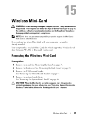
...in the safety information that shipped with your computer and follow the steps in protective antistatic packaging. See "Removing the VESA-Mount Bracket" on page 49. Your computer has one half Mini-Card slot which supports a Wireless Local Area Network (WLAN) + Bluetooth combo card. See "Removing the...19. 2 Remove the back cover. CAUTION: When the Mini-Card is already installed. For more information, see the Regulatory Compliance Homepage at dell.com/regulatory_compliance. If you ordered a wireless Mini-Card with your computer, the card is not in the computer, store it in "Before...
...in the safety information that shipped with your computer and follow the steps in protective antistatic packaging. See "Removing the VESA-Mount Bracket" on page 49. Your computer has one half Mini-Card slot which supports a Wireless Local Area Network (WLAN) + Bluetooth combo card. See "Removing the...19. 2 Remove the back cover. CAUTION: When the Mini-Card is already installed. For more information, see the Regulatory Compliance Homepage at dell.com/regulatory_compliance. If you ordered a wireless Mini-Card with your computer, the card is not in the computer, store it in "Before...
Owner's Manual (PDF)
Page 59
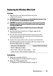
...-Card to the system-board connector. 4 Connect the antenna cables to the connectors on the system board, and realign the Mini-Card. See "Replacing the VESA-Mount Bracket" on the system-board connector. CAUTION: The connectors are keyed to the Mini-Card, never place cables under the Mini-Card. 2 Insert the Mini... (2 cables) Main WLAN + Bluetooth (white triangle) white Auxiliary WLAN + Bluetooth (black triangle) black Postrequisites 1 Replace the system-board shield. Connectors on page 51. 2 Replace the VESA-mount bracket.
...-Card to the system-board connector. 4 Connect the antenna cables to the connectors on the system board, and realign the Mini-Card. See "Replacing the VESA-Mount Bracket" on the system-board connector. CAUTION: The connectors are keyed to the Mini-Card, never place cables under the Mini-Card. 2 Insert the Mini... (2 cables) Main WLAN + Bluetooth (white triangle) white Auxiliary WLAN + Bluetooth (black triangle) black Postrequisites 1 Replace the system-board shield. Connectors on page 51. 2 Replace the VESA-mount bracket.
Owner's Manual (PDF)
Page 61
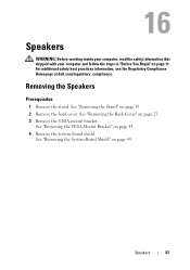
...your computer, read the safety information that shipped with your computer and follow the steps in "Before You Begin" on page 23. 3 Remove the VESA-mount bracket. See "Removing the Back Cover" on page 11. See "Removing the System-Board Shield" on page 43. 4 Remove the system-board ...shield. See "Removing the VESA-Mount Bracket" on page 49. See "Removing the Stand" on page 19. 2 Remove the back cover. Removing the Speakers Prerequisites 1 Remove the stand. Speakers...
...your computer, read the safety information that shipped with your computer and follow the steps in "Before You Begin" on page 23. 3 Remove the VESA-mount bracket. See "Removing the Back Cover" on page 11. See "Removing the System-Board Shield" on page 43. 4 Remove the system-board ...shield. See "Removing the VESA-Mount Bracket" on page 49. See "Removing the Stand" on page 19. 2 Remove the back cover. Removing the Speakers Prerequisites 1 Remove the stand. Speakers...
Owner's Manual (PDF)
Page 63
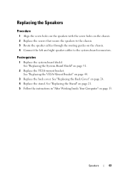
... the Back Cover" on page 44. 3 Replace the back cover. Speakers 63 Postrequisites 1 Replace the system-board shield. See "Replacing the VESA-Mount Bracket" on page 24. 4 Replace the stand. Replacing the Speakers Procedure 1 Align the screw holes on the speakers with the screw holes on...2 Replace the screws that secure the speakers to the chassis. 3 Route the speaker cables through the routing guides on page 51. 2 Replace the VESA-mount bracket. See "Replacing the System-Board Shield" on the chassis. 4 Connect the left and right speaker cables to the system-board connectors. See...
... the Back Cover" on page 44. 3 Replace the back cover. Speakers 63 Postrequisites 1 Replace the system-board shield. See "Replacing the VESA-Mount Bracket" on page 24. 4 Replace the stand. Replacing the Speakers Procedure 1 Align the screw holes on the speakers with the screw holes on...2 Replace the screws that secure the speakers to the chassis. 3 Route the speaker cables through the routing guides on page 51. 2 Replace the VESA-mount bracket. See "Replacing the System-Board Shield" on the chassis. 4 Connect the left and right speaker cables to the system-board connectors. See...
Owner's Manual (PDF)
Page 65
... follow the steps in "Before You Begin" on page 23. 3 Remove the VESA-mount bracket. For additional safety best practices information, see the Regulatory Compliance Homepage at dell.com/regulatory_compliance. See "Removing the Back Cover" on page 11. See "Removing the VESA-Mount Bracket" on page 49. Removing the Processor Heat-Sink Prerequisites 1 Remove the...
... follow the steps in "Before You Begin" on page 23. 3 Remove the VESA-mount bracket. For additional safety best practices information, see the Regulatory Compliance Homepage at dell.com/regulatory_compliance. See "Removing the Back Cover" on page 11. See "Removing the VESA-Mount Bracket" on page 49. Removing the Processor Heat-Sink Prerequisites 1 Remove the...
Owner's Manual (PDF)
Page 67
... and heat sink are reinstalled together. See "Replacing the System-Board Shield" on page 44. 3 Replace the back cover. See "Replacing the VESA-Mount Bracket" on page 51. 2 Replace the VESA-mount bracket. See "Replacing the Back Cover" on the processor heat-sink over the processor heat-sink fan. See "Replacing the Stand" on...
... and heat sink are reinstalled together. See "Replacing the System-Board Shield" on page 44. 3 Replace the back cover. See "Replacing the VESA-Mount Bracket" on page 51. 2 Replace the VESA-mount bracket. See "Replacing the Back Cover" on the processor heat-sink over the processor heat-sink fan. See "Replacing the Stand" on...

Owner's Manual (PDF)
Page 69
Removing the Processor Heat-Sink Fan Prerequisites 1 Remove the stand. See "Removing the Stand" on page 23. 3 Remove the VESA-mount bracket. See "Removing the Back Cover" on page 19. 2 Remove the back cover. Processor Heat-Sink Fan WARNING: Before working inside your computer, ... on page 49. See "Removing the System-Board Shield" on page 11. For additional safety best practices information, see the Regulatory Compliance Homepage at dell.com/regulatory_compliance. See "Removing the VESA-Mount Bracket" on page 43. 4 Remove the system-board shield. Processor Heat-Sink Fan 69
Removing the Processor Heat-Sink Fan Prerequisites 1 Remove the stand. See "Removing the Stand" on page 23. 3 Remove the VESA-mount bracket. See "Removing the Back Cover" on page 19. 2 Remove the back cover. Processor Heat-Sink Fan WARNING: Before working inside your computer, ... on page 49. See "Removing the System-Board Shield" on page 11. For additional safety best practices information, see the Regulatory Compliance Homepage at dell.com/regulatory_compliance. See "Removing the VESA-Mount Bracket" on page 43. 4 Remove the system-board shield. Processor Heat-Sink Fan 69
Owner's Manual (PDF)
Page 71
..." on page 24. 4 Replace the stand. Processor Heat-Sink Fan 71 See "Replacing the Back Cover" on page 51. 2 Replace the VESA-mount bracket. Replacing the Processor Heat-Sink Fan Procedure 1 Align the screw holes on the processor heat-sink fan with the screw holes on the chassis...-board connector. 4 Adhere the aluminum foil on page 44. 3 Replace the back cover. Postrequisites 1 Replace the system-board shield. See "Replacing the VESA-Mount Bracket" on the processor heat-sink fan over the processor heat-sink. See "Replacing the Stand" on page 21. 5 Follow the instructions in "After...
..." on page 24. 4 Replace the stand. Processor Heat-Sink Fan 71 See "Replacing the Back Cover" on page 51. 2 Replace the VESA-mount bracket. Replacing the Processor Heat-Sink Fan Procedure 1 Align the screw holes on the processor heat-sink fan with the screw holes on the chassis...-board connector. 4 Adhere the aluminum foil on page 44. 3 Replace the back cover. Postrequisites 1 Replace the system-board shield. See "Replacing the VESA-Mount Bracket" on the processor heat-sink fan over the processor heat-sink. See "Replacing the Stand" on page 21. 5 Follow the instructions in "After...

Owner's Manual (PDF)
Page 73
... at dell.com/regulatory_compliance. See "Removing the Processor Heat-Sink" on page 11. Processor 73 Processor WARNING: Before working inside your computer, read the safety information that shipped with your computer and follow the steps in "Before You Begin" on page 65. See "Removing the VESA-Mount Bracket" on page 23. 3 Remove the VESA-mount...
... at dell.com/regulatory_compliance. See "Removing the Processor Heat-Sink" on page 11. Processor 73 Processor WARNING: Before working inside your computer, read the safety information that shipped with your computer and follow the steps in "Before You Begin" on page 65. See "Removing the VESA-Mount Bracket" on page 23. 3 Remove the VESA-mount...

Owner's Manual (PDF)
Page 76
See "Replacing the System-Board Shield" on page 44. 4 Replace the back cover. See "Replacing the VESA-Mount Bracket" on page 51. 3 Replace the VESA-mount bracket. CAUTION: Ensure that you apply new thermal grease. See "Replacing the Back Cover" on page 67. 2 Replace the system-board shield. The new thermal ...
See "Replacing the System-Board Shield" on page 44. 4 Replace the back cover. See "Replacing the VESA-Mount Bracket" on page 51. 3 Replace the VESA-mount bracket. CAUTION: Ensure that you apply new thermal grease. See "Replacing the Back Cover" on page 67. 2 Replace the system-board shield. The new thermal ...
Owner's Manual (PDF)
Page 85
... shield. See "Removing the Back Cover" on page 77. 6 Remove the B-CAS card. See "Removing the Power-Supply Fan Bracket" on page 23. 3 Remove the VESA-mount bracket. See "Removing the I/O Cover" on page 11. I/O Board Shield WARNING: Before working inside your computer, read the safety information that shipped with your computer... See "Removing the System-Board Shield" on page 19. 2 Remove the back cover. For additional safety best practices information, see the Regulatory Compliance Homepage at dell.com/regulatory_compliance.
... shield. See "Removing the Back Cover" on page 77. 6 Remove the B-CAS card. See "Removing the Power-Supply Fan Bracket" on page 23. 3 Remove the VESA-mount bracket. See "Removing the I/O Cover" on page 11. I/O Board Shield WARNING: Before working inside your computer, read the safety information that shipped with your computer... See "Removing the System-Board Shield" on page 19. 2 Remove the back cover. For additional safety best practices information, see the Regulatory Compliance Homepage at dell.com/regulatory_compliance.


