Owner's Manual (PDF)
Page 6
16 Speakers 61 Removing the Speakers 61 Replacing the Speakers 63 17 Processor Heat-Sink 65 Removing the Processor Heat-Sink 65 Replacing the Processor Heat-Sink 67 18 Processor Heat-Sink Fan 69 Removing the Processor Heat-Sink Fan 69 Replacing the Processor Heat-Sink Fan 71 19 Processor 73 Removing the Processor 73 Replacing the Processor 75 20 Power-Supply Fan Bracket 77 Removing the Power-Supply Fan Bracket 77 Replacing the Power-Supply Fan Bracket 79 6 Contents
16 Speakers 61 Removing the Speakers 61 Replacing the Speakers 63 17 Processor Heat-Sink 65 Removing the Processor Heat-Sink 65 Replacing the Processor Heat-Sink 67 18 Processor Heat-Sink Fan 69 Removing the Processor Heat-Sink Fan 69 Replacing the Processor Heat-Sink Fan 71 19 Processor 73 Removing the Processor 73 Replacing the Processor 75 20 Power-Supply Fan Bracket 77 Removing the Power-Supply Fan Bracket 77 Replacing the Power-Supply Fan Bracket 79 6 Contents
Owner's Manual (PDF)
Page 7
21 I/O Cover 81 Removing the I/O Cover 81 Replacing the I/O Cover 83 22 I/O Board Shield 85 Removing the I/O Board Shield 85 Replacing the I/O Board Shield 88 23 Power-Supply Unit 89 Removing the Power-Supply Unit 89 Replacing the Power-Supply Unit 91 24 Power-Supply Fan 93 Removing the Power-Supply Fan 93 Replacing the Power-Supply Fan 95 25 TV-In Port 97 Removing the TV-In Port 97 Replacing the TV-In Port 99 Contents 7
21 I/O Cover 81 Removing the I/O Cover 81 Replacing the I/O Cover 83 22 I/O Board Shield 85 Removing the I/O Board Shield 85 Replacing the I/O Board Shield 88 23 Power-Supply Unit 89 Removing the Power-Supply Unit 89 Replacing the Power-Supply Unit 91 24 Power-Supply Fan 93 Removing the Power-Supply Fan 93 Replacing the Power-Supply Fan 95 25 TV-In Port 97 Removing the TV-In Port 97 Replacing the TV-In Port 99 Contents 7
Owner's Manual (PDF)
Page 16
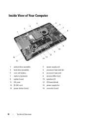
Inside View of Your Computer 4 3 2 1 5 6 7 8 16 15 1 optical-drive assembly 3 hard-drive assembly 5 coin-cell battery 7 memory module(s) 9 system board 11 I/O cover 13 B-CAS card 15 power-button board 11 12 13 14 9 10 2 power-supply unit 4 processor heat-sink fan 6 processor heat-sink 8 wireless Mini-Card 10 speakers (2) 12 I/O board shield 14 power-supply fan 16 converter board 16 Technical Overview
Inside View of Your Computer 4 3 2 1 5 6 7 8 16 15 1 optical-drive assembly 3 hard-drive assembly 5 coin-cell battery 7 memory module(s) 9 system board 11 I/O cover 13 B-CAS card 15 power-button board 11 12 13 14 9 10 2 power-supply unit 4 processor heat-sink fan 6 processor heat-sink 8 wireless Mini-Card 10 speakers (2) 12 I/O board shield 14 power-supply fan 16 converter board 16 Technical Overview
Owner's Manual (PDF)
Page 18
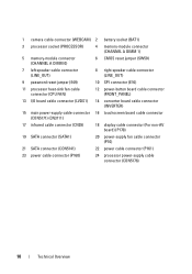
... jumper (E49) 10 SPI connector (E16) 11 processor heat-sink fan cable connector (CPU FAN) 12 power-button board cable connector (FRONT_PANEL) 13 I/O board cable connector (LVDS1) 14 converter board cable connector (INVERTER) 15 main power-supply cable connector 16 touchscreen board cable connector (CON5171) (CN3111) 17 infrared cable connector (CN29) 18 display...
... jumper (E49) 10 SPI connector (E16) 11 processor heat-sink fan cable connector (CPU FAN) 12 power-button board cable connector (FRONT_PANEL) 13 I/O board cable connector (LVDS1) 14 converter board cable connector (INVERTER) 15 main power-supply cable connector 16 touchscreen board cable connector (CON5171) (CN3111) 17 infrared cable connector (CN29) 18 display...
Owner's Manual (PDF)
Page 46
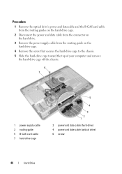
...data cable and the B-CAS card cable from the routing guides on the hard-drive cage. 2 Disconnect the power and data cable from the connector on the hard drive. 3 Remove the power-supply cable from the routing guide on the hard drive cage. 4 Remove the screw that secures the hard-drive ... to the chassis. 5 Slide the hard-drive cage toward the top of your computer and remove the hard-drive cage off the chassis. 6 7 1 power-supply cable 3 routing guide 5 B-CAS card cable 7 hard-drive cage 5 4 3 2 1 2 power and data cable (hard drive) 4 power and date cable (optical drive) 6 screw 46 Hard Drive
...data cable and the B-CAS card cable from the routing guides on the hard-drive cage. 2 Disconnect the power and data cable from the connector on the hard drive. 3 Remove the power-supply cable from the routing guide on the hard drive cage. 4 Remove the screw that secures the hard-drive ... to the chassis. 5 Slide the hard-drive cage toward the top of your computer and remove the hard-drive cage off the chassis. 6 7 1 power-supply cable 3 routing guide 5 B-CAS card cable 7 hard-drive cage 5 4 3 2 1 2 power and data cable (hard drive) 4 power and date cable (optical drive) 6 screw 46 Hard Drive
Owner's Manual (PDF)
Page 48
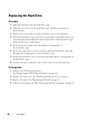
... bracket. Replacing the Hard Drive Procedure 1 Slide the hard drive into the slots on the chassis. 5 Route the power-supply cable through the routing guide on the hard-drive cage. 6 Route the optical drive's power and data cable and the B-CAS card cable through the routing guides on the hard-drive cage. 7 Route... the hard-drive's power and data cable through the routing guide on the hard-drive cage. 8 Connect the power and data cable to the hard drive. 4 Place the hard-drive cage on the chassis and slide it...
... bracket. Replacing the Hard Drive Procedure 1 Slide the hard drive into the slots on the chassis. 5 Route the power-supply cable through the routing guide on the hard-drive cage. 6 Route the optical drive's power and data cable and the B-CAS card cable through the routing guides on the hard-drive cage. 7 Route... the hard-drive's power and data cable through the routing guide on the hard-drive cage. 8 Connect the power and data cable to the hard drive. 4 Place the hard-drive cage on the chassis and slide it...

Owner's Manual (PDF)
Page 77
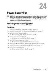
See "Removing the Stand" on page 23. See "Removing the Back Cover" on page 19. 2 Remove the back cover. Power-Supply Fan Bracket WARNING: Before working inside your computer, read the safety information that shipped with your computer and follow the steps in "Before You Begin" on page 11. Removing the Power-Supply Fan Bracket Prerequisites 1 Remove the stand. For additional safety best practices information, see the Regulatory Compliance Homepage at dell.com/regulatory_compliance. Power-Supply Fan Bracket 77
See "Removing the Stand" on page 23. See "Removing the Back Cover" on page 19. 2 Remove the back cover. Power-Supply Fan Bracket WARNING: Before working inside your computer, read the safety information that shipped with your computer and follow the steps in "Before You Begin" on page 11. Removing the Power-Supply Fan Bracket Prerequisites 1 Remove the stand. For additional safety best practices information, see the Regulatory Compliance Homepage at dell.com/regulatory_compliance. Power-Supply Fan Bracket 77

Owner's Manual (PDF)
Page 78
Procedure 1 Disconnect the B-CAS card cable from the connector on the B-CAS card. 2 Remove the screw that secures the power-supply fan bracket to the chassis. 3 Lift the power-supply fan bracket off the chassis. 3 1 2 1 screw 3 B-CAS card cable 2 power-supply fan bracket 78 Power-Supply Fan Bracket
Procedure 1 Disconnect the B-CAS card cable from the connector on the B-CAS card. 2 Remove the screw that secures the power-supply fan bracket to the chassis. 3 Lift the power-supply fan bracket off the chassis. 3 1 2 1 screw 3 B-CAS card cable 2 power-supply fan bracket 78 Power-Supply Fan Bracket
Owner's Manual (PDF)
Page 79
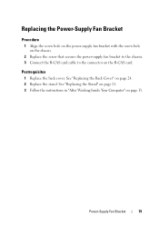
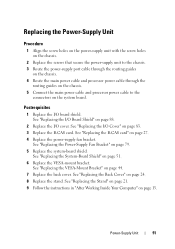
See "Replacing the Stand" on page 21. 3 Follow the instructions in "After Working Inside Your Computer" on the B-CAS card. Replacing the Power-Supply Fan Bracket Procedure 1 Align the screw hole on the power-supply fan bracket with the screw hole on the chassis. 2 Replace the screw that secures the power-supply fan bracket to the chassis. 3 Connect the B-CAS card cable to the connector on page 13. Power-Supply Fan Bracket 79 Postrequisites 1 Replace the back cover. See "Replacing the Back Cover" on page 24. 2 Replace the stand.
See "Replacing the Stand" on page 21. 3 Follow the instructions in "After Working Inside Your Computer" on the B-CAS card. Replacing the Power-Supply Fan Bracket Procedure 1 Align the screw hole on the power-supply fan bracket with the screw hole on the chassis. 2 Replace the screw that secures the power-supply fan bracket to the chassis. 3 Connect the B-CAS card cable to the connector on page 13. Power-Supply Fan Bracket 79 Postrequisites 1 Replace the back cover. See "Replacing the Back Cover" on page 24. 2 Replace the stand.

Owner's Manual (PDF)
Page 85
... Back Cover" on page 19. 2 Remove the back cover. See "Removing the I/O Cover" on page 49. 5 Remove the power-supply fan bracket. For additional safety best practices information, see the Regulatory Compliance Homepage at dell.com/regulatory_compliance. See "Removing the System-Board Shield" on page 81. I /O Board Shield Prerequisites 1 Remove the stand. Removing... safety information that shipped with your computer and follow the steps in "Before You Begin" on page 77. 6 Remove the B-CAS card. See "Removing the Power-Supply Fan Bracket" on page 11.
... Back Cover" on page 19. 2 Remove the back cover. See "Removing the I/O Cover" on page 49. 5 Remove the power-supply fan bracket. For additional safety best practices information, see the Regulatory Compliance Homepage at dell.com/regulatory_compliance. See "Removing the System-Board Shield" on page 81. I /O Board Shield Prerequisites 1 Remove the stand. Removing... safety information that shipped with your computer and follow the steps in "Before You Begin" on page 77. 6 Remove the B-CAS card. See "Removing the Power-Supply Fan Bracket" on page 11.
Owner's Manual (PDF)
Page 86
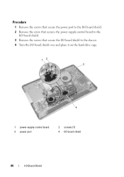
Procedure 1 Remove the screws that secure the power port to the I/O board shield. 2 Remove the screw that secures the power supply control board to the I/O board shield. 3 Remove the screws that secure the I/O board shield to the chassis. 4 Turn the I/O board shield over and place it on the hard-drive cage. 12 3 4 1 power-supply control board 3 power port 2 screws (7) 4 I/O board shield 86 I/O Board Shield
Procedure 1 Remove the screws that secure the power port to the I/O board shield. 2 Remove the screw that secures the power supply control board to the I/O board shield. 3 Remove the screws that secure the I/O board shield to the chassis. 4 Turn the I/O board shield over and place it on the hard-drive cage. 12 3 4 1 power-supply control board 3 power port 2 screws (7) 4 I/O board shield 86 I/O Board Shield

Owner's Manual (PDF)
Page 87
5 Slide the power port and power-supply control board through the slot on the I/O board shield. 6 Disconnect the power-supply fan cable and infrared cable from the system-board connectors. 7 Disconnect the antenna cable from the connector on the TV tuner card. 8 Lift the I/O board shield off the chassis. 1 2 3 4 5 1 I/O board shield 3 antenna cable 5 power-supply fan cable 2 TV tuner card 4 infrared cable I/O Board Shield 87
5 Slide the power port and power-supply control board through the slot on the I/O board shield. 6 Disconnect the power-supply fan cable and infrared cable from the system-board connectors. 7 Disconnect the antenna cable from the connector on the TV tuner card. 8 Lift the I/O board shield off the chassis. 1 2 3 4 5 1 I/O board shield 3 antenna cable 5 power-supply fan cable 2 TV tuner card 4 infrared cable I/O Board Shield 87
Owner's Manual (PDF)
Page 88
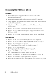
...See "Replacing the System-Board Shield" on page 27. 3 Replace the power-supply fan bracket. See "Replacing the Power-Supply Fan Bracket" on page 44. 6 Replace the back cover. Replacing the I/O Board Shield Procedure 1 Connect the power-supply fan cable and infrared cable to the system-board connectors. 2 Connect the... antenna cable to the connector on the TV tuner card. 3 Slide the power port and the power-supply control board through the slot on the I/O board shield. 4 Align the screw holes on the I/O board shield with the screw...
...See "Replacing the System-Board Shield" on page 27. 3 Replace the power-supply fan bracket. See "Replacing the Power-Supply Fan Bracket" on page 44. 6 Replace the back cover. Replacing the I/O Board Shield Procedure 1 Connect the power-supply fan cable and infrared cable to the system-board connectors. 2 Connect the... antenna cable to the connector on the TV tuner card. 3 Slide the power port and the power-supply control board through the slot on the I/O board shield. 4 Align the screw holes on the I/O board shield with the screw...
Owner's Manual (PDF)
Page 89
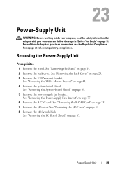
... /O cover. See "Removing the Back Cover" on page 19. 2 Remove the back cover. Power-Supply Unit 89 See "Removing the Stand" on page 23. 3 Remove the VESA-mount bracket. See "Removing the Power-Supply Fan Bracket" on page 25. 7 Remove the I /O board shield. See "Removing the ... the VESA-Mount Bracket" on page 11. For additional safety best practices information, see the Regulatory Compliance Homepage at dell.com/regulatory_compliance. Power-Supply Unit WARNING: Before working inside your computer, read the safety information that shipped with your computer and follow the steps...
... /O cover. See "Removing the Back Cover" on page 19. 2 Remove the back cover. Power-Supply Unit 89 See "Removing the Stand" on page 23. 3 Remove the VESA-mount bracket. See "Removing the Power-Supply Fan Bracket" on page 25. 7 Remove the I /O board shield. See "Removing the ... the VESA-Mount Bracket" on page 11. For additional safety best practices information, see the Regulatory Compliance Homepage at dell.com/regulatory_compliance. Power-Supply Unit WARNING: Before working inside your computer, read the safety information that shipped with your computer and follow the steps...
Owner's Manual (PDF)
Page 90
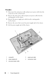
Procedure 1 Disconnect the main power cable and processor power cable from the connectors on the system board. 2 Remove the main power cable and processor power cable from the routing guides on the chassis. 3 Remove the power-supply port cable from the routing guides on the chassis. 4 Remove the screws that secure the power-supply unit to the chassis. 5 Lift the power-supply unit off the chassis. 1 5 1 screws (4) 3 power-supply unit 5 processor power cable 4 3 2 2 power-port cable 4 main power cable 90 Power-Supply Unit
Procedure 1 Disconnect the main power cable and processor power cable from the connectors on the system board. 2 Remove the main power cable and processor power cable from the routing guides on the chassis. 3 Remove the power-supply port cable from the routing guides on the chassis. 4 Remove the screws that secure the power-supply unit to the chassis. 5 Lift the power-supply unit off the chassis. 1 5 1 screws (4) 3 power-supply unit 5 processor power cable 4 3 2 2 power-port cable 4 main power cable 90 Power-Supply Unit
Owner's Manual (PDF)
Page 91
... Follow the instructions in "After Working Inside Your Computer" on page 79. 5 Replace the system-board shield. Power-Supply Unit 91 See "Replacing the I /O board shield. See "Replacing the Power-Supply Fan Bracket" on page 13. See "Replacing the VESA-Mount Bracket" on page 51. 6 Replace the VESA...44. 7 Replace the back cover. Replacing the Power-Supply Unit Procedure 1 Align the screw holes on the power-supply unit with the screw holes on the chassis. 2 Replace the screws that secure the power-supply unit to the chassis. 3 Route the power-supply port cable through the routing guides on the ...
... Follow the instructions in "After Working Inside Your Computer" on page 79. 5 Replace the system-board shield. Power-Supply Unit 91 See "Replacing the I /O board shield. See "Replacing the Power-Supply Fan Bracket" on page 13. See "Replacing the VESA-Mount Bracket" on page 51. 6 Replace the VESA...44. 7 Replace the back cover. Replacing the Power-Supply Unit Procedure 1 Align the screw holes on the power-supply unit with the screw holes on the chassis. 2 Replace the screws that secure the power-supply unit to the chassis. 3 Route the power-supply port cable through the routing guides on the ...
Owner's Manual (PDF)
Page 93
...on page 19. 2 Remove the back cover. See "Removing the VESA-Mount Bracket" on page 11. See "Removing the I /O cover. Power-Supply Fan WARNING: Before working inside your computer, read the safety information that shipped with your computer and follow the steps in "Before You Begin" ...on page 43. 4 Remove the system-board shield. See "Removing the I/O Cover" on page 49. 5 Remove the power-supply fan bracket. Removing the Power-Supply Fan Prerequisites 1 Remove the stand. See "Removing the System-Board Shield" on page 81. 8 Remove the I/O board shield. See "Removing...
...on page 19. 2 Remove the back cover. See "Removing the VESA-Mount Bracket" on page 11. See "Removing the I /O cover. Power-Supply Fan WARNING: Before working inside your computer, read the safety information that shipped with your computer and follow the steps in "Before You Begin" ...on page 43. 4 Remove the system-board shield. See "Removing the I/O Cover" on page 49. 5 Remove the power-supply fan bracket. Removing the Power-Supply Fan Prerequisites 1 Remove the stand. See "Removing the System-Board Shield" on page 81. 8 Remove the I/O board shield. See "Removing...

Owner's Manual (PDF)
Page 94
Procedure 1 Remove the screws that secure the power-supply fan to the I/O board shield. 2 Lift the power-supply fan off the I/O board shield. 1 power-supply fan 2 1 2 screws (2) 94 Power-Supply Fan
Procedure 1 Remove the screws that secure the power-supply fan to the I/O board shield. 2 Lift the power-supply fan off the I/O board shield. 1 power-supply fan 2 1 2 screws (2) 94 Power-Supply Fan

Owner's Manual (PDF)
Page 95
... back cover. See "Replacing the VESA-Mount Bracket" on page 27. 4 Replace the power-supply fan bracket. See "Replacing the System-Board Shield" on page 79. 5 Replace the system-board shield. See "Replacing the Power-Supply Fan Bracket" on page 51. 6 Replace the VESA-mount bracket. See "Replacing the ... Inside Your Computer" on page 24. 8 Replace the stand. See "Replacing the Back Cover" on page 13. Replacing the Power-Supply Fan Procedure 1 Align the screw holes on the power-supply fan with the screw holes on the I/O board shield. 2 Replace the screws that secure the...
... back cover. See "Replacing the VESA-Mount Bracket" on page 27. 4 Replace the power-supply fan bracket. See "Replacing the System-Board Shield" on page 79. 5 Replace the system-board shield. See "Replacing the Power-Supply Fan Bracket" on page 51. 6 Replace the VESA-mount bracket. See "Replacing the ... Inside Your Computer" on page 24. 8 Replace the stand. See "Replacing the Back Cover" on page 13. Replacing the Power-Supply Fan Procedure 1 Align the screw holes on the power-supply fan with the screw holes on the I/O board shield. 2 Replace the screws that secure the...
Owner's Manual (PDF)
Page 97
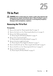
See "Removing the Stand" on page 49. 5 Remove the power-supply fan bracket. See "Removing the System-Board Shield" on page 19. 2 Remove the back cover. TV-In Port 97 See "Removing the Back Cover" on .... See "Removing the I/O Cover" on page 77. 6 Remove the B-CAS card. See "Removing the Power-Supply Fan Bracket" on page 81. 8 Remove the I/O board shield. For additional safety best practices information, see the Regulatory Compliance Homepage at dell.com/regulatory_compliance. Removing the TV-In Port Prerequisites 1 Remove the stand. TV-In Port WARNING...
See "Removing the Stand" on page 49. 5 Remove the power-supply fan bracket. See "Removing the System-Board Shield" on page 19. 2 Remove the back cover. TV-In Port 97 See "Removing the Back Cover" on .... See "Removing the I/O Cover" on page 77. 6 Remove the B-CAS card. See "Removing the Power-Supply Fan Bracket" on page 81. 8 Remove the I/O board shield. For additional safety best practices information, see the Regulatory Compliance Homepage at dell.com/regulatory_compliance. Removing the TV-In Port Prerequisites 1 Remove the stand. TV-In Port WARNING...


