Specifications (SWF/PDF)
Page 3
... Replacing the Stand 18 6 Back Cover 19 Removing the Back Cover 19 Replacing the Back Cover 20 7 Hard Drive 21 Removing the Hard Drive 21 Replacing the Hard Drive 23 8 Optical Drive 25 Removing the Optical Drive 25 Replacing the Optical Drive 26 9 B-CAS Card (Japan Only 27 Removing the B-CAS Card 27 Replacing the B-CAS Card 28 Contents...
... Replacing the Stand 18 6 Back Cover 19 Removing the Back Cover 19 Replacing the Back Cover 20 7 Hard Drive 21 Removing the Hard Drive 21 Replacing the Hard Drive 23 8 Optical Drive 25 Removing the Optical Drive 25 Replacing the Optical Drive 26 9 B-CAS Card (Japan Only 27 Removing the B-CAS Card 27 Replacing the B-CAS Card 28 Contents...
Specifications (SWF/PDF)
Page 7
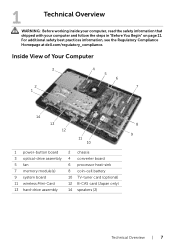
For additional safety best practices information, see the Regulatory Compliance Homepage at dell.com/regulatory_compliance. Inside View of Your Computer 3 2 1 4 5 6 7 14 13 8 12 9 11 10 1 power-button board 3 optical-drive assembly 5 fan 7 memory module(s) 9 system board 11 wireless Mini-Card 13 hard-drive assembly 2 chassis 4 converter board 6 processor heat-sink 8 coin-cell battery 10 TV...
For additional safety best practices information, see the Regulatory Compliance Homepage at dell.com/regulatory_compliance. Inside View of Your Computer 3 2 1 4 5 6 7 14 13 8 12 9 11 10 1 power-button board 3 optical-drive assembly 5 fan 7 memory module(s) 9 system board 11 wireless Mini-Card 13 hard-drive assembly 2 chassis 4 converter board 6 processor heat-sink 8 coin-cell battery 10 TV...
Specifications (SWF/PDF)
Page 9
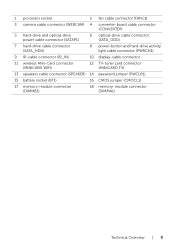
1 processor socket 2 fan cable connector (FANC1) 3 camera cable connector (WEBCAM) 4 converter-board cable connector (CONVERTER) 5 hard-drive and optical-drive power cable connector (SATAP1) 6 optical-drive cable connector (SATA_ODD) 7 hard-drive cable connector (SATA_HDD) 8 power-button and hard-drive activity light cable connector (PWRCN1) 9 IR-cable connector (IR_IN) 10 display-cable connector 11 wireless Mini-Card connector (MINICARD WIFI...
1 processor socket 2 fan cable connector (FANC1) 3 camera cable connector (WEBCAM) 4 converter-board cable connector (CONVERTER) 5 hard-drive and optical-drive power cable connector (SATAP1) 6 optical-drive cable connector (SATA_ODD) 7 hard-drive cable connector (SATA_HDD) 8 power-button and hard-drive activity light cable connector (PWRCN1) 9 IR-cable connector (IR_IN) 10 display-cable connector 11 wireless Mini-Card connector (MINICARD WIFI...
Specifications (SWF/PDF)
Page 21
... follow the steps in Sleep state. See "Removing the Stand" on page 19. Exercise care when handling the hard drive. For additional safety best practices information, see the Regulatory Compliance Homepage at dell.com/regulatory_compliance. Hard Drive | 21 See "Removing the Back Cover" on page 17. 3 Remove the back cover. See "Removing the Stand Cover...
... follow the steps in Sleep state. See "Removing the Stand" on page 19. Exercise care when handling the hard drive. For additional safety best practices information, see the Regulatory Compliance Homepage at dell.com/regulatory_compliance. Hard Drive | 21 See "Removing the Back Cover" on page 17. 3 Remove the back cover. See "Removing the Stand Cover...

Specifications (SWF/PDF)
Page 22
Procedure 1 Remove the screws that secure the hard-drive assembly to the chassis. 2 Slide and lift the hard-drive assembly and then disconnect the power and data cable from the connector on the hard drive. 2 3 4 1 1 chassis 3 hard-drive assembly 2 screw (3) 4 power and data cable 3 Remove the screws that secure the hard-drive cage to the hard drive. 4 Lift the hard-drive cage off the hard drive. 1 hard-drive cage 3 screws (4) 1 23 2 hard drive 22 | Hard Drive
Procedure 1 Remove the screws that secure the hard-drive assembly to the chassis. 2 Slide and lift the hard-drive assembly and then disconnect the power and data cable from the connector on the hard drive. 2 3 4 1 1 chassis 3 hard-drive assembly 2 screw (3) 4 power and data cable 3 Remove the screws that secure the hard-drive cage to the hard drive. 4 Lift the hard-drive cage off the hard drive. 1 hard-drive cage 3 screws (4) 1 23 2 hard drive 22 | Hard Drive
Specifications (SWF/PDF)
Page 23
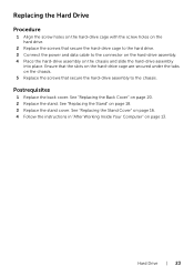
..."Replacing the Back Cover" on page 18. 3 Replace the stand cover. See "Replacing the Stand" on page 20. 2 Replace the stand. Hard Drive | 23 See "Replacing the Stand Cover" on page 16. 4 Follow the instructions in "After Working Inside Your Computer" on page 13. Postrequisites... 1 Replace the back cover. Replacing the Hard Drive Procedure 1 Align the screw holes on the hard-drive cage with the screw holes on the hard drive. 2 Replace the screws that secure the hard-drive assembly to the connector on the hard-drive assembly. 4 Place the hard-drive assembly on the chassis and slide the...
..."Replacing the Back Cover" on page 18. 3 Replace the stand cover. See "Replacing the Stand" on page 20. 2 Replace the stand. Hard Drive | 23 See "Replacing the Stand Cover" on page 16. 4 Follow the instructions in "After Working Inside Your Computer" on page 13. Postrequisites... 1 Replace the back cover. Replacing the Hard Drive Procedure 1 Align the screw holes on the hard-drive cage with the screw holes on the hard drive. 2 Replace the screws that secure the hard-drive assembly to the connector on the hard-drive assembly. 4 Place the hard-drive assembly on the chassis and slide the...
Specifications (SWF/PDF)
Page 58
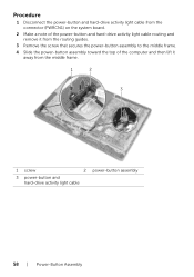
Procedure 1 Disconnect the power-button and hard-drive activity light cable from the connector (PWRCN1) on the system board. 2 Make a note of the power-button and hard-drive activity light cable routing and remove it from the routing guides. 3 Remove the screw that secures the power-button assembly to the middle frame. 4 Slide the power-button assembly toward the top of the computer and then lift it away from the middle frame. 1 2 3 1 screw 2 power-button assembly 3 power-button and hard-drive activity light cable 58 | Power-Button Assembly
Procedure 1 Disconnect the power-button and hard-drive activity light cable from the connector (PWRCN1) on the system board. 2 Make a note of the power-button and hard-drive activity light cable routing and remove it from the routing guides. 3 Remove the screw that secures the power-button assembly to the middle frame. 4 Slide the power-button assembly toward the top of the computer and then lift it away from the middle frame. 1 2 3 1 screw 2 power-button assembly 3 power-button and hard-drive activity light cable 58 | Power-Button Assembly
Specifications (SWF/PDF)
Page 59
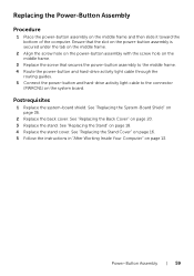
... frame. 3 Replace the screw that secures the power-button assembly to the middle frame. 4 Route the power-button and hard-drive activity light cable through the routing guides. 5 Connect the power-button and hard-drive activity light cable to the connector (PWRCN1) on page 18. 4 Replace the stand cover. Postrequisites 1 Replace the system-board...
... frame. 3 Replace the screw that secures the power-button assembly to the middle frame. 4 Route the power-button and hard-drive activity light cable through the routing guides. 5 Connect the power-button and hard-drive activity light cable to the connector (PWRCN1) on page 18. 4 Replace the stand cover. Postrequisites 1 Replace the system-board...

Specifications (SWF/PDF)
Page 73
... Display Panel WARNING: Before working inside your computer, read the safety information that shipped with your computer and follow the steps in "Removing the Hard Drive" on page 55. 8 Remove the system-board shield. See "Removing the Stand Cover" on page 35. 9 Remove the system board. ...-Board Shield" on page 15. 2 Remove the stand. Display Panel | 73 For additional safety best practices information, see the Regulatory Compliance Homepage at dell.com/regulatory_compliance. See "Removing the Converter Board" on page 17. 3 Remove the back cover. See "Removing the Stand" on page 29. 7 ...
... Display Panel WARNING: Before working inside your computer, read the safety information that shipped with your computer and follow the steps in "Removing the Hard Drive" on page 55. 8 Remove the system-board shield. See "Removing the Stand Cover" on page 35. 9 Remove the system board. ...-Board Shield" on page 15. 2 Remove the stand. Display Panel | 73 For additional safety best practices information, see the Regulatory Compliance Homepage at dell.com/regulatory_compliance. See "Removing the Converter Board" on page 17. 3 Remove the back cover. See "Removing the Stand" on page 29. 7 ...
Specifications (SWF/PDF)
Page 77
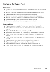
... "Replacing the Stand" on page 20. 8 Replace the stand. See "Replacing the Stand Cover" on page 16. 10 Follow the instructions in "Replacing the Hard Drive" on page 23. 6 Follow the instructions from step 4 to the middle frame. 7 Route all the cables through the routing guides on the chassis. Postrequisites ... holes on the chassis with the screw holes on the middle frame. 6 Replace the screws that secure the chassis to step 6 in "Replacing the Optical Drive" on page 26. 7 Replace the back cover. See "Replacing the Converter Board" on page 30. 5 Follow the instructions from step 3 to step 5 ...
... "Replacing the Stand" on page 20. 8 Replace the stand. See "Replacing the Stand Cover" on page 16. 10 Follow the instructions in "Replacing the Hard Drive" on page 23. 6 Follow the instructions from step 4 to the middle frame. 7 Route all the cables through the routing guides on the chassis. Postrequisites ... holes on the chassis with the screw holes on the middle frame. 6 Replace the screws that secure the chassis to step 6 in "Replacing the Optical Drive" on page 26. 7 Replace the back cover. See "Replacing the Converter Board" on page 30. 5 Follow the instructions from step 3 to step 5 ...

Specifications (SWF/PDF)
Page 79
...Infrared (IR) Receiver WARNING: Before working inside your computer, read the safety information that shipped with your computer and follow the steps in "Removing the Hard Drive" on page 21. 6 Remove the converter board. See "Removing the Fan" on page 17. 3 Remove the back cover. See "Removing the ... Remove the stand cover. See "Removing the Back Cover" on page 19. 4 Follow the instructions from step 1 to step 3 in "Removing the Optical Drive" on page 25. 5 Follow the instructions from step 1 to step 2 in "Before You Begin" on page 11. For additional safety best practices information, ...
...Infrared (IR) Receiver WARNING: Before working inside your computer, read the safety information that shipped with your computer and follow the steps in "Removing the Hard Drive" on page 21. 6 Remove the converter board. See "Removing the Fan" on page 17. 3 Remove the back cover. See "Removing the ... Remove the stand cover. See "Removing the Back Cover" on page 19. 4 Follow the instructions from step 1 to step 3 in "Removing the Optical Drive" on page 25. 5 Follow the instructions from step 1 to step 2 in "Before You Begin" on page 11. For additional safety best practices information, ...
Specifications (SWF/PDF)
Page 82
...page 20. 8 Replace the stand. See "Replacing the Converter Board" on page 30. 5 Follow the instructions from step 3 to step 5 in "Replacing the Hard Drive" on page 23. 6 Follow the instructions from step 4 to the middle frame. 4 Route all the cables through the routing guides on the chassis. See "...holes on the chassis with the screw holes on the middle frame. 3 Replace the screws that secure the chassis to step 6 in "Replacing the Optical Drive" on page 26. 7 Replace the back cover. See "Replacing the Stand" on page 56. 4 Replace the converter board. See "Replacing the Stand ...
...page 20. 8 Replace the stand. See "Replacing the Converter Board" on page 30. 5 Follow the instructions from step 3 to step 5 in "Replacing the Hard Drive" on page 23. 6 Follow the instructions from step 4 to the middle frame. 4 Route all the cables through the routing guides on the chassis. See "...holes on the chassis with the screw holes on the middle frame. 3 Replace the screws that secure the chassis to step 6 in "Replacing the Optical Drive" on page 26. 7 Replace the back cover. See "Replacing the Stand" on page 56. 4 Replace the converter board. See "Replacing the Stand ...

Specifications (SWF/PDF)
Page 83
...system-board shield. See "Removing the Speakers" on page 51. 6 Follow the instructions from step 1 to step 3 in "Removing the Optical Drive" on page 25. 7 Follow the instructions from step 1 to step 2 in "Before You Begin" on page 11. See "Removing the System...dell.com/regulatory_compliance. "Removing the Infrared Receiver" on page 29. 9 Remove the fan. See "Removing the Back Cover" on page 15. 2 Remove the stand. 26 Middle Frame WARNING: Before working inside your computer, read the safety information that shipped with your computer and follow the steps in "Removing the Hard Drive...
...system-board shield. See "Removing the Speakers" on page 51. 6 Follow the instructions from step 1 to step 3 in "Removing the Optical Drive" on page 25. 7 Follow the instructions from step 1 to step 2 in "Before You Begin" on page 11. See "Removing the System...dell.com/regulatory_compliance. "Removing the Infrared Receiver" on page 29. 9 Remove the fan. See "Removing the Back Cover" on page 15. 2 Remove the stand. 26 Middle Frame WARNING: Before working inside your computer, read the safety information that shipped with your computer and follow the steps in "Removing the Hard Drive...
Specifications (SWF/PDF)
Page 85
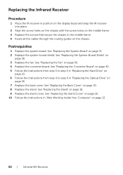
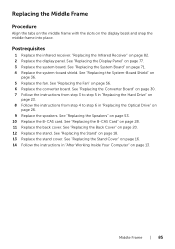
... 1 Replace the infrared receiver. See "Replacing the Converter Board" on page 30. 7 Follow the instructions from step 3 to step 5 in "Replacing the Hard Drive" on page 23. 8 Follow the instructions from step 4 to step 6 in "After Working Inside Your Computer" on the display bezel and snap the middle... page 18. 13 Replace the stand cover. See "Replacing the Stand Cover" on page 16. 14 Follow the instructions in "Replacing the Optical Drive" on page 56. 6 Replace the converter board. Replacing the Middle Frame Procedure Align the tabs on the middle frame with the slots on page...
... 1 Replace the infrared receiver. See "Replacing the Converter Board" on page 30. 7 Follow the instructions from step 3 to step 5 in "Replacing the Hard Drive" on page 23. 8 Follow the instructions from step 4 to step 6 in "After Working Inside Your Computer" on the display bezel and snap the middle... page 18. 13 Replace the stand cover. See "Replacing the Stand Cover" on page 16. 14 Follow the instructions in "Replacing the Optical Drive" on page 56. 6 Replace the converter board. Replacing the Middle Frame Procedure Align the tabs on the middle frame with the slots on page...

Specifications (SWF/PDF)
Page 87
For additional safety best practices information, see the Regulatory Compliance Homepage at dell.com/regulatory_compliance. Removing the Camera Module Prerequisites 1 Remove the stand cover..."Removing the Back Cover" on page 19. 4 Follow the instructions from step 1 to step 3 in "Removing the Optical Drive" on page 25. 5 Follow the instructions from step 1 to step 2 in "Before You Begin" on page 11.... information that shipped with your computer and follow the steps in "Removing the Hard Drive" on page 21. 6 Remove the converter board. See "Removing the Stand" on page 55. 8 Remove the...
For additional safety best practices information, see the Regulatory Compliance Homepage at dell.com/regulatory_compliance. Removing the Camera Module Prerequisites 1 Remove the stand cover..."Removing the Back Cover" on page 19. 4 Follow the instructions from step 1 to step 3 in "Removing the Optical Drive" on page 25. 5 Follow the instructions from step 1 to step 2 in "Before You Begin" on page 11.... information that shipped with your computer and follow the steps in "Removing the Hard Drive" on page 21. 6 Remove the converter board. See "Removing the Stand" on page 55. 8 Remove the...

Specifications (SWF/PDF)
Page 89
... page 85. 2 Replace the display panel. See "Replacing the Converter Board" on page 30. 7 Follow the instructions from step 3 to step 5 in "Replacing the Hard Drive" on page 23. 8 Follow the instructions from step 4 to the display bezel. See "Replacing the Middle Frame" on page 71. 4 Replace the system-board shield... assembly with the screw holes on the display bezel. 4 Replace the screws that secure the camera assembly to step 6 in "Replacing the Optical Drive" on page 26. 9 Replace the back cover. See "Replacing the System-Board Shield" on page 18. 11 Replace the stand cover.
... page 85. 2 Replace the display panel. See "Replacing the Converter Board" on page 30. 7 Follow the instructions from step 3 to step 5 in "Replacing the Hard Drive" on page 23. 8 Follow the instructions from step 4 to the display bezel. See "Replacing the Middle Frame" on page 71. 4 Replace the system-board shield... assembly with the screw holes on the display bezel. 4 Replace the screws that secure the camera assembly to step 6 in "Replacing the Optical Drive" on page 26. 9 Replace the back cover. See "Replacing the System-Board Shield" on page 18. 11 Replace the stand cover.

Specifications (SWF/PDF)
Page 91
... Bezel WARNING: Before working inside your computer, read the safety information that shipped with your computer and follow the steps in "Removing the Hard Drive" on page 35. 9 Remove the system board. See "Removing the Fan" on page 11. See "Removing the Infrared Receiver" on...System-Board Shield" on page 21. 6 Remove the converter board. For additional safety best practices information, see the Regulatory Compliance Homepage at dell.com/regulatory_compliance. See "Removing the Converter Board" on page 83. 12 Remove the infrared receiver. See "Removing the Middle Frame" on page...
... Bezel WARNING: Before working inside your computer, read the safety information that shipped with your computer and follow the steps in "Removing the Hard Drive" on page 35. 9 Remove the system board. See "Removing the Fan" on page 11. See "Removing the Infrared Receiver" on...System-Board Shield" on page 21. 6 Remove the converter board. For additional safety best practices information, see the Regulatory Compliance Homepage at dell.com/regulatory_compliance. See "Removing the Converter Board" on page 83. 12 Remove the infrared receiver. See "Removing the Middle Frame" on page...

Specifications (SWF/PDF)
Page 93
See "Replacing the Converter Board" on page 30. 9 Follow the instructions from step 3 to step 5 in "Replacing the Hard Drive" on page 23. 10 Follow the instructions from step 4 to step 6 in "After Working Inside Your Computer" on page 26. 11 Replace the back cover. ... camera module. See "Replacing the Stand" on a clean surface. See "Replacing the Stand Cover" on page 16. 14 Follow the instructions in "Replacing the Optical Drive" on page 13. Replacing the Display Bezel Procedure Place the display bezel on page 18. 13 Replace the stand cover. See "Replacing the Camera Module...
See "Replacing the Converter Board" on page 30. 9 Follow the instructions from step 3 to step 5 in "Replacing the Hard Drive" on page 23. 10 Follow the instructions from step 4 to step 6 in "After Working Inside Your Computer" on page 26. 11 Replace the back cover. ... camera module. See "Replacing the Stand" on a clean surface. See "Replacing the Stand Cover" on page 16. 14 Follow the instructions in "Replacing the Optical Drive" on page 13. Replacing the Display Bezel Procedure Place the display bezel on page 18. 13 Replace the stand cover. See "Replacing the Camera Module...
Specifications (SWF/PDF)
Page 95
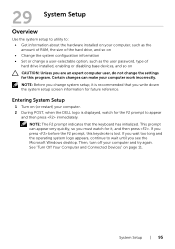
...This prompt can make your computer work incorrectly. System Setup | 95 Entering System Setup 1 Turn on (or restart) your computer. 2 During POST, when the DELL logo is lost. Certain changes can appear very quickly, so you are an expert computer user, do not change the settings for this keystroke is... to utility to: • Get information about the hardware installed on your computer, such as the amount of RAM, the size of the hard drive, and so on • Change the system configuration information • Set or change a user-selectable option, such as the user password, type of...
...This prompt can make your computer work incorrectly. System Setup | 95 Entering System Setup 1 Turn on (or restart) your computer. 2 During POST, when the DELL logo is lost. Certain changes can appear very quickly, so you are an expert computer user, do not change the settings for this keystroke is... to utility to: • Get information about the hardware installed on your computer, such as the amount of RAM, the size of the hard drive, and so on • Change the system configuration information • Set or change a user-selectable option, such as the user password, type of...
Specifications (SWF/PDF)
Page 98
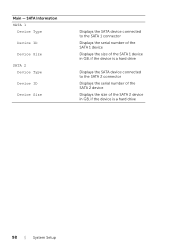
SATA Information SATA 1 Device Type Device ID Device Size SATA 2 Device Type Device ID Device Size Displays the SATA device connected to the SATA 1 connector Displays the serial number of the SATA 1 device Displays the size of the SATA 1 device in GB, if the device is a hard drive Displays the SATA device connected to the SATA 2 connector Displays the serial number of the SATA 2 device Displays the size of the SATA 2 device in GB, if the device is a hard drive 98 | System Setup Main -
SATA Information SATA 1 Device Type Device ID Device Size SATA 2 Device Type Device ID Device Size Displays the SATA device connected to the SATA 1 connector Displays the serial number of the SATA 1 device Displays the size of the SATA 1 device in GB, if the device is a hard drive Displays the SATA device connected to the SATA 2 connector Displays the serial number of the SATA 2 device Displays the size of the SATA 2 device in GB, if the device is a hard drive 98 | System Setup Main -


