
Service Manual
Page 3
Contents 1 Before You Begin 9 Recommended Tools 9 Turning Off Your Computer 9 Before Working Inside Your Computer 10 2 Top Cover 13 Removing the Top Cover 13 Replacing the Top Cover 14 3 Battery 15 Removing the Battery 15 Replacing the Battery 16 4 Module Cover 17 Removing the Module Cover 17 Replacing the Module Cover 18 5 Memory Module(s 19 Removing the Memory Module(s 19 Contents 3
Contents 1 Before You Begin 9 Recommended Tools 9 Turning Off Your Computer 9 Before Working Inside Your Computer 10 2 Top Cover 13 Removing the Top Cover 13 Replacing the Top Cover 14 3 Battery 15 Removing the Battery 15 Replacing the Battery 16 4 Module Cover 17 Removing the Module Cover 17 Replacing the Module Cover 18 5 Memory Module(s 19 Removing the Memory Module(s 19 Contents 3

Service Manual
Page 4
Replacing the Memory Module(s 20 6 Optical Drive 23 Removing the Optical Drive 23 Replacing the Optical Drive 24 7 Keyboard 27 Removing the Keyboard 27 Replacing the Keyboard 29 8 Palm-Rest Assembly 31 Removing the Palm-Rest Assembly 31 Replacing the Palm-Rest Assembly 34 9 Wireless Mini-Card(s 37 Removing the Mini-Card(s 37 Replacing the Mini-Card(s 39 10 Display 41 Display Assembly 41 Removing the Display Assembly 41 Replacing the Display Assembly 43 Display Bezel 44 4 Contents
Replacing the Memory Module(s 20 6 Optical Drive 23 Removing the Optical Drive 23 Replacing the Optical Drive 24 7 Keyboard 27 Removing the Keyboard 27 Replacing the Keyboard 29 8 Palm-Rest Assembly 31 Removing the Palm-Rest Assembly 31 Replacing the Palm-Rest Assembly 34 9 Wireless Mini-Card(s 37 Removing the Mini-Card(s 37 Replacing the Mini-Card(s 39 10 Display 41 Display Assembly 41 Removing the Display Assembly 41 Replacing the Display Assembly 43 Display Bezel 44 4 Contents

Service Manual
Page 5
Removing the Display Bezel 44 Replacing the Display Bezel 45 Display Panel 46 Removing the Display Panel 46 Replacing the Display Panel 47 Display Cable 48 Removing the Display Cable 48 Replacing the Display Cable 49 Display-Panel Brackets 50 Removing the Display-Panel Brackets 50 Replacing the Display-Panel Brackets 50 11 Hinge Cover 53 Removing the Hinge Cover 53 Replacing the Hinge Cover 55 12 Camera Module 57 Removing the Camera Module 57 Replacing the Camera Module 58 13 Coin-Cell Battery 61 Removing the Coin-Cell Battery 61 Replacing the Coin-Cell Battery 62...
Removing the Display Bezel 44 Replacing the Display Bezel 45 Display Panel 46 Removing the Display Panel 46 Replacing the Display Panel 47 Display Cable 48 Removing the Display Cable 48 Replacing the Display Cable 49 Display-Panel Brackets 50 Removing the Display-Panel Brackets 50 Replacing the Display-Panel Brackets 50 11 Hinge Cover 53 Removing the Hinge Cover 53 Replacing the Hinge Cover 55 12 Camera Module 57 Removing the Camera Module 57 Replacing the Camera Module 58 13 Coin-Cell Battery 61 Removing the Coin-Cell Battery 61 Replacing the Coin-Cell Battery 62...

Service Manual
Page 6
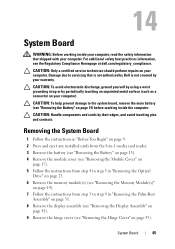
14 System Board 65 Removing the System Board 65 Replacing the System Board 66 Entering the Service Tag in the BIOS 68 15 Speakers 69 Removing the Speakers 69 Replacing the Speakers 70 16 Hard Drive 71 Removing the Hard Drive 71 Replacing the Hard Drive 73 17 Thermal-Cooling Assembly 75 Removing the Thermal-Cooling Assembly 75 Replacing the Thermal-Cooling Assembly 76 18 Processor Module 79 Removing the Processor Module 79 Replacing the Processor Module 80 6 Contents
14 System Board 65 Removing the System Board 65 Replacing the System Board 66 Entering the Service Tag in the BIOS 68 15 Speakers 69 Removing the Speakers 69 Replacing the Speakers 70 16 Hard Drive 71 Removing the Hard Drive 71 Replacing the Hard Drive 73 17 Thermal-Cooling Assembly 75 Removing the Thermal-Cooling Assembly 75 Replacing the Thermal-Cooling Assembly 76 18 Processor Module 79 Removing the Processor Module 79 Replacing the Processor Module 80 6 Contents

Service Manual
Page 10
... you connect a cable, ensure that shipped with your computer. Also, before you pull connectors apart, keep them evenly aligned to avoid bending any installed cards from the 8-in on a card. WARNING: Before working inside your computer, read the safety information that both connectors are disconnecting this type of cable, press in -1 media card reader. 5 Disconnect your computer and all attached devices from potential...
... you connect a cable, ensure that shipped with your computer. Also, before you pull connectors apart, keep them evenly aligned to avoid bending any installed cards from the 8-in on a card. WARNING: Before working inside your computer, read the safety information that both connectors are disconnecting this type of cable, press in -1 media card reader. 5 Disconnect your computer and all attached devices from potential...

Service Manual
Page 11
Before You Begin 11 CAUTION: To help prevent damage to the system board, remove the main battery (see "Removing the Battery" on page 15) before working inside the computer. 7 Remove the battery (see "Removing the Battery" on page 15). 8 Turn the computer top-side up, open the display, and press the power button to ground the system board.
Before You Begin 11 CAUTION: To help prevent damage to the system board, remove the main battery (see "Removing the Battery" on page 15) before working inside the computer. 7 Remove the battery (see "Removing the Battery" on page 15). 8 Turn the computer top-side up, open the display, and press the power button to ground the system board.
Service Manual
Page 13
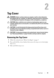
... system board, remove the main battery (see the Regulatory Compliance Homepage at dell.com/regulatory_compliance. CAUTION: To avoid electrostatic discharge, ground yourself by using a wrist grounding strap or by your warranty. CAUTION: Only a certified service technician should perform repairs on page 9. 2 Press and hold the release button that shipped with your computer. Top Cover 13 Removing the Top Cover 1 Follow the instructions...
... system board, remove the main battery (see the Regulatory Compliance Homepage at dell.com/regulatory_compliance. CAUTION: To avoid electrostatic discharge, ground yourself by using a wrist grounding strap or by your warranty. CAUTION: Only a certified service technician should perform repairs on page 9. 2 Press and hold the release button that shipped with your computer. Top Cover 13 Removing the Top Cover 1 Follow the instructions...
Service Manual
Page 17
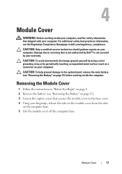
... secures the module cover to the system board, remove the main battery (see the Regulatory Compliance Homepage at dell.com/regulatory_compliance. Removing the Module Cover 1 Follow the instructions in "Before You Begin" on page 9. 2 Remove the battery (see "Removing the Battery" on the computer base. 5 Lift the module cover off the computer base. CAUTION: Only a certified service technician should perform repairs on your computer. Module Cover 17 4 Module Cover WARNING: Before working inside...
... secures the module cover to the system board, remove the main battery (see the Regulatory Compliance Homepage at dell.com/regulatory_compliance. Removing the Module Cover 1 Follow the instructions in "Before You Begin" on page 9. 2 Remove the battery (see "Removing the Battery" on the computer base. 5 Lift the module cover off the computer base. CAUTION: Only a certified service technician should perform repairs on your computer. Module Cover 17 4 Module Cover WARNING: Before working inside...
Service Manual
Page 19
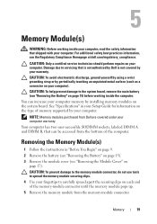
... spread apart the securing clips on each end of memory supported by installing memory modules on your computer. CAUTION: Only a certified service technician should perform repairs on your fingertips to the system board, remove the main battery (see "Removing the Battery" on page 15) before working inside the computer. See "Specifications" in "Before You Begin" on page 9. 2 Remove the battery (see "Removing the Battery" on the type of the memory-module connector...
... spread apart the securing clips on each end of memory supported by installing memory modules on your computer. CAUTION: Only a certified service technician should perform repairs on your fingertips to the system board, remove the main battery (see "Removing the Battery" on page 15) before working inside the computer. See "Specifications" in "Before You Begin" on page 9. 2 Remove the battery (see "Removing the Battery" on the type of the memory-module connector...

Service Manual
Page 20
... install a memory module in the connector labeled "DIMM B." 1 Follow the instructions in "Before You Begin" on page 9. 2 Align the notch in the memory module with the tab in the memory-module connector. 3 Slide the memory module firmly into the slot at a 45-degree angle, and press the memory module down until it . 1 3 2 1 memory-module connector 2 securing clips (2) 3 memory module Replacing the Memory Module(s) CAUTION: If you need to install memory modules in two connectors, install a memory module...
... install a memory module in the connector labeled "DIMM B." 1 Follow the instructions in "Before You Begin" on page 9. 2 Align the notch in the memory module with the tab in the memory-module connector. 3 Slide the memory module firmly into the slot at a 45-degree angle, and press the memory module down until it . 1 3 2 1 memory-module connector 2 securing clips (2) 3 memory module Replacing the Memory Module(s) CAUTION: If you need to install memory modules in two connectors, install a memory module...

Service Manual
Page 39
... stripe black with gray stripe 6 If you are replacing the WiMax/WWAN Mini-Card: Replace the module cover (see "Replacing the Module Cover" on the system board, and realign the card. Replacing the Mini-Card(s) 1 Follow the instructions in "Before You Begin" on the system board and replace the screw that secures the Mini-Card to the system board. 5 Connect the appropriate antenna cables to the Mini-Card you are keyed to...
... stripe black with gray stripe 6 If you are replacing the WiMax/WWAN Mini-Card: Replace the module cover (see "Replacing the Module Cover" on the system board, and realign the card. Replacing the Mini-Card(s) 1 Follow the instructions in "Before You Begin" on the system board and replace the screw that secures the Mini-Card to the system board. 5 Connect the appropriate antenna cables to the Mini-Card you are keyed to...
Service Manual
Page 40
NOTE: If you must install the appropriate drivers and utilities. 40 Wireless Mini-Card(s) Follow the instructions from a source other than Dell, you are installing a communication card from step 4 to the computer. 9 Install the drivers and utilities for your computer, as required. Failure to do so may result in damage to step 8 in "Replacing the Palm-Rest Assembly" on page 34. 8 Replace the battery (see "Replacing the Battery" on the computer, replace all screws and ensure that no stray screws remain inside the computer. CAUTION: Before turning on page 16).
NOTE: If you must install the appropriate drivers and utilities. 40 Wireless Mini-Card(s) Follow the instructions from a source other than Dell, you are installing a communication card from step 4 to the computer. 9 Install the drivers and utilities for your computer, as required. Failure to do so may result in damage to step 8 in "Replacing the Palm-Rest Assembly" on page 34. 8 Replace the battery (see "Replacing the Battery" on the computer, replace all screws and ensure that no stray screws remain inside the computer. CAUTION: Before turning on page 16).

Service Manual
Page 44
... when removing it to prevent damaging the display bezel. 4 Using your fingertips, carefully pry up the inside the computer. Display Bezel Removing the Display Bezel 1 Follow the instructions in "Before You Begin" on page 9. 2 Remove the top cover (see "Removing the Top Cover" on page 13). 3 Remove the display assembly (see "Replacing the Battery" on page 16). CAUTION: Before turning on page 41). 5 Connect the display cable and touch-screen cable to...
... when removing it to prevent damaging the display bezel. 4 Using your fingertips, carefully pry up the inside the computer. Display Bezel Removing the Display Bezel 1 Follow the instructions in "Before You Begin" on page 9. 2 Remove the top cover (see "Removing the Top Cover" on page 13). 3 Remove the display assembly (see "Replacing the Battery" on page 16). CAUTION: Before turning on page 41). 5 Connect the display cable and touch-screen cable to...

Service Manual
Page 55
... the hinge cover with the slots on the computer base and snap the hinge cover into place. 3 Replace the four screws that secure the hinge cover to the computer. Hinge Cover 55 1 Hinge Cover Replacing the Hinge Cover 1 Follow the instructions in damage to the computer base. 4 Replace the display assembly (see "Replacing the Display Assembly" on page 43). 5 Replace the battery (see "Replacing the Battery" on the...
... the hinge cover with the slots on the computer base and snap the hinge cover into place. 3 Replace the four screws that secure the hinge cover to the computer. Hinge Cover 55 1 Hinge Cover Replacing the Hinge Cover 1 Follow the instructions in damage to the computer base. 4 Replace the display assembly (see "Replacing the Display Assembly" on page 43). 5 Replace the battery (see "Replacing the Battery" on the...

Service Manual
Page 57
... 9. 2 Remove the battery (see "Removing the Battery" on page 15). 3 Follow the instructions from the display back cover. 8 Remove the camera module. 12 Camera Module WARNING: Before working inside your computer, read the safety information that is not authorized by Dell is not covered by your computer. Camera Module 57 For additional safety best practices information, see "Removing the Display Panel" on your computer). CAUTION: Only a certified service technician should perform repairs...
... 9. 2 Remove the battery (see "Removing the Battery" on page 15). 3 Follow the instructions from the display back cover. 8 Remove the camera module. 12 Camera Module WARNING: Before working inside your computer, read the safety information that is not authorized by Dell is not covered by your computer. Camera Module 57 For additional safety best practices information, see "Removing the Display Panel" on your computer). CAUTION: Only a certified service technician should perform repairs...
Service Manual
Page 65
... any installed cards from the 8-in-1 media card reader. 3 Remove the battery (see "Removing the Battery" on page 15). 4 Remove the module cover (see "Removing the Module Cover" on page 17). 5 Follow the instructions from step 4 to step 5 in "Removing the Optical Drive" on page 23. 6 Remove the memory module(s) (see "Removing the Memory Module(s)" on page 19). 7 Follow the instructions from step 3 to the system board, remove the main battery (see the Regulatory Compliance Homepage at dell.com...
... any installed cards from the 8-in-1 media card reader. 3 Remove the battery (see "Removing the Battery" on page 15). 4 Remove the module cover (see "Removing the Module Cover" on page 17). 5 Follow the instructions from step 4 to step 5 in "Removing the Optical Drive" on page 23. 6 Remove the memory module(s) (see "Removing the Memory Module(s)" on page 19). 7 Follow the instructions from step 3 to the system board, remove the main battery (see the Regulatory Compliance Homepage at dell.com...

Service Manual
Page 67
... Memory Module(s)" on page 20). 14 Replace the module cover (see "Replacing the Module Cover" on page 18). 15 Replace the battery (see "Replacing the Display Assembly" on page 43). 12 Follow the instructions from the 8-in-1 media card reader. Failure to the computer. 17 Turn on the computer. NOTE: After you have replaced the system board, enter the computer Service Tag in damage to do so may result in the BIOS...
... Memory Module(s)" on page 20). 14 Replace the module cover (see "Replacing the Module Cover" on page 18). 15 Replace the battery (see "Replacing the Display Assembly" on page 43). 12 Follow the instructions from the 8-in-1 media card reader. Failure to the computer. 17 Turn on the computer. NOTE: After you have replaced the system board, enter the computer Service Tag in damage to do so may result in the BIOS...

Service Manual
Page 68
Entering the Service Tag in the BIOS 1 Ensure that the AC adapter is plugged in and that the main battery is installed properly. 2 Turn on the computer. 3 Press during POST to enter the system setup program. 4 Navigate to the security tab and enter the service tag in the BIOS" on page 68). 18 Enter the service tag (see "Entering the Service Tag in the Set Service Tag field. 68 System Board
Entering the Service Tag in the BIOS 1 Ensure that the AC adapter is plugged in and that the main battery is installed properly. 2 Turn on the computer. 3 Press during POST to enter the system setup program. 4 Navigate to the security tab and enter the service tag in the BIOS" on page 68). 18 Enter the service tag (see "Entering the Service Tag in the Set Service Tag field. 68 System Board
Service Manual
Page 71
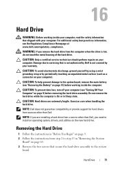
... install an operating system, drivers, and utilities on your computer). CAUTION: Only a certified service technician should perform repairs on page 65. 3 Remove the two screws that secure the hard-drive assembly to step 13 in "Removing the System Board" on your computer. Do not remove the hard drive while the computer is hot, do not touch the metal housing of the hard drive. Exercise care when handling the hard drive. Removing...
... install an operating system, drivers, and utilities on your computer). CAUTION: Only a certified service technician should perform repairs on page 65. 3 Remove the two screws that secure the hard-drive assembly to step 13 in "Removing the System Board" on your computer. Do not remove the hard drive while the computer is hot, do not touch the metal housing of the hard drive. Exercise care when handling the hard drive. Removing...

Service Manual
Page 73
... or shipping the hard drive. 3 Place the hard drive in "Replacing the System Board" on the system board. 6 Slide the hard-drive assembly to connect it to the system-board connector. 7 Replace the two screws that secure the hard drive to the system-board. 8 Follow the instructions from its packaging. Hard Drive 73 2 1 1 screws (4) 2 hard-drive bracket Replacing the Hard Drive 1 Follow the instructions in "Before You Begin" on page 9. 2 Remove the new hard drive from step 6 to...
... or shipping the hard drive. 3 Place the hard drive in "Replacing the System Board" on the system board. 6 Slide the hard-drive assembly to connect it to the system-board connector. 7 Replace the two screws that secure the hard drive to the system-board. 8 Follow the instructions from its packaging. Hard Drive 73 2 1 1 screws (4) 2 hard-drive bracket Replacing the Hard Drive 1 Follow the instructions in "Before You Begin" on page 9. 2 Remove the new hard drive from step 6 to...


