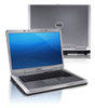
Owners Manual
Page 3
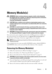
Contents 1 Before You Begin 9 Recommended Tools 9 Turning Off Your Computer 9 Before Working Inside Your Computer 10 2 Battery 13 Removing the Battery 13 Replacing the Battery 14 3 Keyboard 15 Removing the Keyboard 15 Replacing the Keyboard 17 4 Memory Module(s 19 Removing the Memory Module(s 19 Replacing the Memory Module(s 20 5 Optical Drive 23 Removing the Optical Drive 23 Contents 3
Contents 1 Before You Begin 9 Recommended Tools 9 Turning Off Your Computer 9 Before Working Inside Your Computer 10 2 Battery 13 Removing the Battery 13 Replacing the Battery 14 3 Keyboard 15 Removing the Keyboard 15 Replacing the Keyboard 17 4 Memory Module(s 19 Removing the Memory Module(s 19 Replacing the Memory Module(s 20 5 Optical Drive 23 Removing the Optical Drive 23 Contents 3
Owners Manual
Page 15
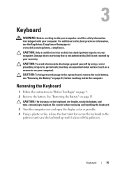
... touching an unpainted metal surface (such as possible. 4 Using a plastic scribe, release the four tabs that is not authorized by Dell is not covered by your computer. For additional safety best practices information, see "Removing the Battery" on your computer). Be careful ... open the display as far as a connector on the keyboard are fragile, easily dislodged, and time-consuming to the system board, remove the main battery, see the Regulatory Compliance Homepage at www.dell.com/regulatory_compliance. 3 Keyboard WARNING: Before working inside your computer, read the safety...
... touching an unpainted metal surface (such as possible. 4 Using a plastic scribe, release the four tabs that is not authorized by Dell is not covered by your computer. For additional safety best practices information, see "Removing the Battery" on your computer). Be careful ... open the display as far as a connector on the keyboard are fragile, easily dislodged, and time-consuming to the system board, remove the main battery, see the Regulatory Compliance Homepage at www.dell.com/regulatory_compliance. 3 Keyboard WARNING: Before working inside your computer, read the safety...

Owners Manual
Page 16
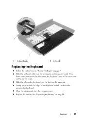
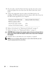
1 2 3 1 plastic scribe 3 keyboard 2 tabs (4) CAUTION: The keycaps on the system board and remove the keyboard cable. 7 Lift the keyboard off the computer. 16 Keyboard Be careful when removing and handling the keyboard. 5 Carefully turn the keyboard over and place it on the palm rest assembly. 6 Lift the connector latch that secures the keyboard cable to the connector on the keyboard are fragile, easily dislodged, and time-consuming to replace.
1 2 3 1 plastic scribe 3 keyboard 2 tabs (4) CAUTION: The keycaps on the system board and remove the keyboard cable. 7 Lift the keyboard off the computer. 16 Keyboard Be careful when removing and handling the keyboard. 5 Carefully turn the keyboard over and place it on the palm rest assembly. 6 Lift the connector latch that secures the keyboard cable to the connector on the keyboard are fragile, easily dislodged, and time-consuming to replace.
Owners Manual
Page 17
Keyboard 17 Press down on the connector latch to secure the keyboard cable to lock the four tabs securing the keyboard. 5 Close the display and turn the computer over. 6 Replace the battery. See "Replacing the Battery" on page 14. 1 2 1 keyboard cable 2 keyboard Replacing the Keyboard 1 Follow the instructions in "Before You Begin" on page 9. 2 Slide the keyboard cable into the slots on the palm rest. 4 Gently press around the edges of the keyboard to the connector on the system board. 3 Slide the tabs on the keyboard into the connector on the system board.
Keyboard 17 Press down on the connector latch to secure the keyboard cable to lock the four tabs securing the keyboard. 5 Close the display and turn the computer over. 6 Replace the battery. See "Replacing the Battery" on page 14. 1 2 1 keyboard cable 2 keyboard Replacing the Keyboard 1 Follow the instructions in "Before You Begin" on page 9. 2 Slide the keyboard cable into the slots on the palm rest. 4 Gently press around the edges of the keyboard to the connector on the system board. 3 Slide the tabs on the keyboard into the connector on the system board.
Owners Manual
Page 19
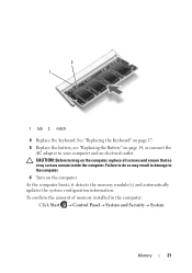
See the Specifications at www.dell.com/regulatory_compliance. Your computer has two user-accessible SODIMM sockets, labeled DIMM A and DIMM B, that can increase your computer memory by your computer. See "Removing the Keyboard" on page 13. 3 Remove the keyboard. See "Removing the Battery" on ...19 CAUTION: To help prevent damage to the system board, remove the main battery, see the Regulatory Compliance Homepage at support.dell.com/manuals for information on your computer. NOTE: Memory modules purchased from the bottom of memory supported by periodically touching an...
See the Specifications at www.dell.com/regulatory_compliance. Your computer has two user-accessible SODIMM sockets, labeled DIMM A and DIMM B, that can increase your computer memory by your computer. See "Removing the Keyboard" on page 13. 3 Remove the keyboard. See "Removing the Battery" on ...19 CAUTION: To help prevent damage to the system board, remove the main battery, see the Regulatory Compliance Homepage at support.dell.com/manuals for information on your computer. NOTE: Memory modules purchased from the bottom of memory supported by periodically touching an...
Owners Manual
Page 21
... an electrical outlet. As the computer boots, it detects the memory module(s) and automatically updates the system configuration information. 2 1 1 tab 2 notch 4 Replace the keyboard. See "Replacing the Keyboard" on page 17. 5 Replace the battery, see "Replacing the Battery" on page 14, or connect the AC adapter to the computer. 6 Turn on the...
... an electrical outlet. As the computer boots, it detects the memory module(s) and automatically updates the system configuration information. 2 1 1 tab 2 notch 4 Replace the keyboard. See "Replacing the Keyboard" on page 17. 5 Replace the battery, see "Replacing the Battery" on page 14, or connect the AC adapter to the computer. 6 Turn on the...
Owners Manual
Page 23
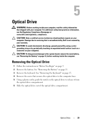
... a connector on your computer). Removing the Optical Drive 1 Follow the instructions in "Before You Begin" on page 13. 3 Remove the keyboard. See "Removing the Keyboard" on page 15. 4 Remove the screw that secures the optical drive to the computer base. 5 Using a plastic scribe, push the ...notch on the optical drive to the system board, remove the main battery, see the Regulatory Compliance Homepage at www.dell.com/regulatory_compliance. ...
... a connector on your computer). Removing the Optical Drive 1 Follow the instructions in "Before You Begin" on page 13. 3 Remove the keyboard. See "Removing the Keyboard" on page 15. 4 Remove the screw that secures the optical drive to the computer base. 5 Using a plastic scribe, push the ...notch on the optical drive to the system board, remove the main battery, see the Regulatory Compliance Homepage at www.dell.com/regulatory_compliance. ...
Owners Manual
Page 24
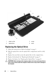
.... 5 Replace the battery. CAUTION: Before turning on the computer, replace all screws and ensure that secures the optical drive to the computer base. 4 Replace the keyboard. Failure to do so may result in "Before You Begin" on page 9. 2 Slide the optical drive into the optical-drive compartment until it is fully... computer. 1 2 3 4 1 plastic scribe 3 optical drive 2 screw 4 notch Replacing the Optical Drive 1 Follow the instructions in damage to the computer. 24 Optical Drive See "Replacing the Keyboard" on page 24.
.... 5 Replace the battery. CAUTION: Before turning on the computer, replace all screws and ensure that secures the optical drive to the computer base. 4 Replace the keyboard. Failure to do so may result in "Before You Begin" on page 9. 2 Slide the optical drive into the optical-drive compartment until it is fully... computer. 1 2 3 4 1 plastic scribe 3 optical drive 2 screw 4 notch Replacing the Optical Drive 1 Follow the instructions in damage to the computer. 24 Optical Drive See "Replacing the Keyboard" on page 24.
Owners Manual
Page 25
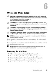
...: Depending on page 15. 4 Disconnect the antenna cables from sources other than Dell. CAUTION: To help prevent damage to the system board. If you ordered a wireless Mini-Card with your warranty. Wireless Mini-Card 25 See "Removing the Keyboard" on the configuration of the computer when it was sold, the Mini-Card...
...: Depending on page 15. 4 Disconnect the antenna cables from sources other than Dell. CAUTION: To help prevent damage to the system board. If you ordered a wireless Mini-Card with your warranty. Wireless Mini-Card 25 See "Removing the Keyboard" on the configuration of the computer when it was sold, the Mini-Card...
Owners Manual
Page 28
4 Press the other than Dell, you are installing. Failure to do so may result in damage to the... drivers and utilities. 28 Wireless Mini-Card Connectors on page 17. 7 Replace the battery. See "Replacing the Keyboard" on the Mini-Card WLAN (2 antenna cables) Main WLAN (white triangle) Auxiliary WLAN (black triangle) Antenna Cable Color ...Scheme white black 6 Replace the keyboard. CAUTION: Before turning on page 14. See "Replacing the Battery" on the computer, replace all screws and ...
4 Press the other than Dell, you are installing. Failure to do so may result in damage to the... drivers and utilities. 28 Wireless Mini-Card Connectors on page 17. 7 Replace the battery. See "Replacing the Keyboard" on the Mini-Card WLAN (2 antenna cables) Main WLAN (white triangle) Auxiliary WLAN (black triangle) Antenna Cable Color ...Scheme white black 6 Replace the keyboard. CAUTION: Before turning on page 14. See "Replacing the Battery" on the computer, replace all screws and ...
Owners Manual
Page 30
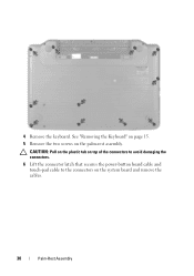
See "Removing the Keyboard" on page 15. 5 Remove the two screws on the system board and remove the cables. 30 Palm-Rest Assembly 4 Remove the keyboard. CAUTION: Pull on the plastic tab on top of the connectors to avoid damaging the connectors. 6 Lift the connector latch that secures the power-button board cable and touch-pad cable to the connectors on the palm-rest assembly.
See "Removing the Keyboard" on page 15. 5 Remove the two screws on the system board and remove the cables. 30 Palm-Rest Assembly 4 Remove the keyboard. CAUTION: Pull on the plastic tab on top of the connectors to avoid damaging the connectors. 6 Lift the connector latch that secures the power-button board cable and touch-pad cable to the connectors on the palm-rest assembly.

Owners Manual
Page 32
... 9. 2 Replace the power button board. Replacing the Palm-Rest Assembly 1 Follow the instructions in "Before You Begin" on the palm-rest assembly. 6 Replace the keyboard. See "Replacing the Keyboard" on page 35. See "Removing the Power Button Board" on page 17. 32 Palm-Rest Assembly 2 1 1 palm-rest assembly 2 plastic scribe 9 Remove the...
... 9. 2 Replace the power button board. Replacing the Palm-Rest Assembly 1 Follow the instructions in "Before You Begin" on the palm-rest assembly. 6 Replace the keyboard. See "Replacing the Keyboard" on page 35. See "Removing the Power Button Board" on page 17. 32 Palm-Rest Assembly 2 1 1 palm-rest assembly 2 plastic scribe 9 Remove the...
Owners Manual
Page 67
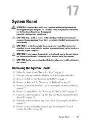
... the system board, remove the main battery, see the Regulatory Compliance Homepage at www.dell.com/regulatory_compliance. CAUTION: To help prevent damage to servicing that shipped with your warranty. See "Removing the Keyboard" on page 45. See "Removing the Thermal Cooling Assembly" on page 15. ...5 Remove the memory module(s). System Board 67 See "Removing the Memory Module(s)" on page 13. 4 Remove the keyboard. Removing the System Board 1 Follow the instructions in "Before You Begin" on page 9. 2 Press and eject any installed cards from the 3-...
... the system board, remove the main battery, see the Regulatory Compliance Homepage at www.dell.com/regulatory_compliance. CAUTION: To help prevent damage to servicing that shipped with your warranty. See "Removing the Keyboard" on page 45. See "Removing the Thermal Cooling Assembly" on page 15. ...5 Remove the memory module(s). System Board 67 See "Removing the Memory Module(s)" on page 13. 4 Remove the keyboard. Removing the System Board 1 Follow the instructions in "Before You Begin" on page 9. 2 Press and eject any installed cards from the 3-...
Owners Manual
Page 70
9 Follow the instructions from step 3 to the computer. 15 Turn on the computer. See "Replacing the Keyboard" on page 20. 12 Replace the keyboard. See "Replacing the Battery" on page 14. 14 Replace any removed cards or blanks in the 3-in the BIOS" on page 70. NOTE: After you ...
9 Follow the instructions from step 3 to the computer. 15 Turn on the computer. See "Replacing the Keyboard" on page 20. 12 Replace the keyboard. See "Replacing the Battery" on page 14. 14 Replace any removed cards or blanks in the 3-in the BIOS" on page 70. NOTE: After you ...


