Service Manual
Page 6
... Post-requisites...69 47 Removing the processor...70 Prerequisites...70 Procedure...70 48 Replacing the processor...72 Procedure...72 Post-requisites...72 49 Removing the power-supply unit 73 Prerequisites...73 Procedure...73 50 Replacing the power-supply unit 75 Procedure...75 Post-requisites...75 6 Contents
... Post-requisites...69 47 Removing the processor...70 Prerequisites...70 Procedure...70 48 Replacing the processor...72 Procedure...72 Post-requisites...72 49 Removing the power-supply unit 73 Prerequisites...73 Procedure...73 50 Replacing the power-supply unit 75 Procedure...75 Post-requisites...75 6 Contents
Service Manual
Page 13
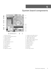
... connector 17. USB 2.0 cable connector 10. SATA0 connector 16. M.2 SATA connector 18. processor socket 22. coin-cell battery 19. jumper plug 21. USB 3.0 cable connector 8. power-supply unit cable connector 12. graphics-card slot 23. processor-fan cable connector 6. PCIe slot 4 26.
... connector 17. USB 2.0 cable connector 10. SATA0 connector 16. M.2 SATA connector 18. processor socket 22. coin-cell battery 19. jumper plug 21. USB 3.0 cable connector 8. power-supply unit cable connector 12. graphics-card slot 23. processor-fan cable connector 6. PCIe slot 4 26.
Service Manual
Page 14
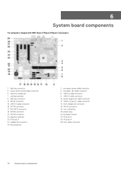
fan-jumper pin 2. power-supply unit cable connector 12. coin-cell battery 20. PCIe slot 4 28. light-bar connector 3. wireless-card slot 9. SATA1 connector 13. USB 3.0 cable connector 15. PCIe slot 3 27. processor-power cable connector 4. USB 3.0 cable connector 8. front chassis-fan connector... processor socket 24. PCIe slot 2 26. graphics-card slot 25. front-audio connector 14 System board components SATA2 connector 18. power-button board cable connector 5. jumper plug 22. memory-module slot 7. SATA3 connector 23. USB 3.1 (Type-C) cable connector 14...
fan-jumper pin 2. power-supply unit cable connector 12. coin-cell battery 20. PCIe slot 4 28. light-bar connector 3. wireless-card slot 9. SATA1 connector 13. USB 3.0 cable connector 15. PCIe slot 3 27. processor-power cable connector 4. USB 3.0 cable connector 8. front chassis-fan connector... processor socket 24. PCIe slot 2 26. graphics-card slot 25. front-audio connector 14 System board components SATA2 connector 18. power-button board cable connector 5. jumper plug 22. memory-module slot 7. SATA3 connector 23. USB 3.1 (Type-C) cable connector 14...
Service Manual
Page 16
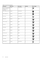
Screw list(continued) Component Secured to Fan (only with computers Chassis shipped with AMD Ryzen 3/Ryzen 5/Ryzen 7 processors) Power-supply unit cover Chassis Power-supply unit Chassis Front cover Chassis Optical drive Chassis Front I/O panel Chassis Top cover Chassis Front bezel Chassis Antenna Chassis Left-side cover Chassis Bottom cover ...
Screw list(continued) Component Secured to Fan (only with computers Chassis shipped with AMD Ryzen 3/Ryzen 5/Ryzen 7 processors) Power-supply unit cover Chassis Power-supply unit Chassis Front cover Chassis Optical drive Chassis Front I/O panel Chassis Top cover Chassis Front bezel Chassis Antenna Chassis Left-side cover Chassis Bottom cover ...

Service Manual
Page 73
... clip and disconnect the power-supply unit cable from the processor-power cable. 3. Press the securing clip and disconnect the power-supply unit cable from the system board. 4. Disconnect the power cables from their extensions. 1. Removing the power-supply unit 73 NOTE: For...power-supply unit NOTE: Before working inside your computer, read the safety information that you can replace them correctly. After working inside your computer, follow the steps in After working inside your computer. For more safety best practices, see the Regulatory Compliance home page at www.dell...
... clip and disconnect the power-supply unit cable from the processor-power cable. 3. Press the securing clip and disconnect the power-supply unit cable from the system board. 4. Disconnect the power cables from their extensions. 1. Removing the power-supply unit 73 NOTE: For...power-supply unit NOTE: Before working inside your computer, read the safety information that you can replace them correctly. After working inside your computer, follow the steps in After working inside your computer. For more safety best practices, see the Regulatory Compliance home page at www.dell...

Service Manual
Page 74
Press the clamp and slide the power-supply unit towards the front of the chassis and lift the power-supply unit, along with the cables, off the chassis. 74 Removing the power-supply unit 5. Remove the four screws (6-32UNCx6.3) that secure the power-supply unit to the chassis. 6.
Press the clamp and slide the power-supply unit towards the front of the chassis and lift the power-supply unit, along with the cables, off the chassis. 74 Removing the power-supply unit 5. Remove the four screws (6-32UNCx6.3) that secure the power-supply unit to the chassis. 6.

Service Manual
Page 75
... home page at www.dell.com/regulatory_compliance. NOTE: For computers with your computer and follow the instructions in After working inside your computer. After working inside your computer, follow the steps in an upright position. Post-requisites Replace the right-side cover. Align the screw holes on the power-supply unit with the...
... home page at www.dell.com/regulatory_compliance. NOTE: For computers with your computer and follow the instructions in After working inside your computer. After working inside your computer, follow the steps in an upright position. Post-requisites Replace the right-side cover. Align the screw holes on the power-supply unit with the...

Service Manual
Page 90
For more safety best practices, see the Regulatory Compliance home page at www.dell.com/regulatory_compliance. Remove the top cover. 4. Remove the bottom cover. After working inside your computer, follow the steps in After working inside your computer. Remove the power-supply unit. 3. Procedure 1. Remove the right-side cover. 2. Lift the top bracket off...
For more safety best practices, see the Regulatory Compliance home page at www.dell.com/regulatory_compliance. Remove the top cover. 4. Remove the bottom cover. After working inside your computer, follow the steps in After working inside your computer. Remove the power-supply unit. 3. Procedure 1. Remove the right-side cover. 2. Lift the top bracket off...

Service Manual
Page 92
... safety information that secures the top bracket to the chassis. 4. For more safety best practices, see the Regulatory Compliance home page at www.dell.com/regulatory_compliance. Replace the power-supply unit. 5. Topics: • Procedure • Post-requisites Procedure 1. Replace the top cover. 4. Replace the two screw (M3x5) that shipped with your computer and...
... safety information that secures the top bracket to the chassis. 4. For more safety best practices, see the Regulatory Compliance home page at www.dell.com/regulatory_compliance. Replace the power-supply unit. 5. Topics: • Procedure • Post-requisites Procedure 1. Replace the top cover. 4. Replace the two screw (M3x5) that shipped with your computer and...

Service Manual
Page 93
... the system board. 2. Removing the system board 93 For more safety best practices, see the Regulatory Compliance home page at www.dell.com/regulatory_compliance. Remove the right-side cover. 2. Procedure NOTE: Note the routing of the connectors so that you replace the system... working inside your computer. Disconnect the USB 2.0 cable from the system board. 6. Remove the processor. Press the securing clip and disconnect the power-supply unit cable from the system board. 7. NOTE: Before disconnecting the cables from the system board. 5. Remove the memory module. 3. Remove the...
... the system board. 2. Removing the system board 93 For more safety best practices, see the Regulatory Compliance home page at www.dell.com/regulatory_compliance. Remove the right-side cover. 2. Procedure NOTE: Note the routing of the connectors so that you replace the system... working inside your computer. Disconnect the USB 2.0 cable from the system board. 6. Remove the processor. Press the securing clip and disconnect the power-supply unit cable from the system board. 7. NOTE: Before disconnecting the cables from the system board. 5. Remove the memory module. 3. Remove the...

Service Manual
Page 95
...from fan-jumper pin to incorrect jumper setting. Route the front-audio cable, fan cable, processor-power cable, power-button board cable, power-supply unit cable, USB 2.0 cable, USB 3.0 cable, optical-drive power cable, hard-drive cables, and USB 3.1 Type-C port cable (optional) through their respective ...to the BIOS using the BIOS setup program. For more safety best practices, see the Regulatory Compliance home page at www.dell.com/regulatory_compliance. Post-requisites 1. You must make the appropriate changes again after you replace the system board. Replacement system board...
...from fan-jumper pin to incorrect jumper setting. Route the front-audio cable, fan cable, processor-power cable, power-button board cable, power-supply unit cable, USB 2.0 cable, USB 3.0 cable, optical-drive power cable, hard-drive cables, and USB 3.1 Type-C port cable (optional) through their respective ...to the BIOS using the BIOS setup program. For more safety best practices, see the Regulatory Compliance home page at www.dell.com/regulatory_compliance. Post-requisites 1. You must make the appropriate changes again after you replace the system board. Replacement system board...

Service Manual
Page 100
...of a functioning machine. Boot Failure: The computer is receiving electrical power, and power supplied by the power supply is in a normal mode. This does not indicate a fault condition. The system LED is integrated on the power supply is working appropriately before the boot process begins. Solid White Blinking...image is found, but it meets the basic computer requirements and the hardware is a system fault error condition, including the power supply. 69 Diagnostics The following table provides the different LED states and what they indicate. If the computer passes the POST,...
...of a functioning machine. Boot Failure: The computer is receiving electrical power, and power supplied by the power supply is in a normal mode. This does not indicate a fault condition. The system LED is integrated on the power supply is working appropriately before the boot process begins. Solid White Blinking...image is found, but it meets the basic computer requirements and the hardware is a system fault error condition, including the power supply. 69 Diagnostics The following table provides the different LED states and what they indicate. If the computer passes the POST,...

Inspiron Gaming Desktop Setup and Specifications
Page 14
For more information, see Me and My Dell at www.dell.com/ support/manuals. NOTE: You can customize the power-button behavior in Power Options. Back 1 Power port Connect a power cable to provide power to your computer. 2 Power-supply diagnostics button Press to check the power‑supply state. 3 Power-supply diagnostics light Indicates the power-supply state. 14
For more information, see Me and My Dell at www.dell.com/ support/manuals. NOTE: You can customize the power-button behavior in Power Options. Back 1 Power port Connect a power cable to provide power to your computer. 2 Power-supply diagnostics button Press to check the power‑supply state. 3 Power-supply diagnostics light Indicates the power-supply state. 14


