Service Manual
Page 4
Procedure...26 16 Replacing the optical drive...27 Procedure...27 Post-requisites...27 17 Removing the light bar...28 Prerequisites...28 Procedure...28 18 Replacing the light bar...29 Procedure...29 Post-requisites...29 19 Removing the memory module 30 Prerequisites...30 Procedure...30 20 Replacing the memory module 32 Procedure...32 Post-requisites...32 21 Removing the front I/O-panel...33 Prerequisites...33 Procedure...
Procedure...26 16 Replacing the optical drive...27 Procedure...27 Post-requisites...27 17 Removing the light bar...28 Prerequisites...28 Procedure...28 18 Replacing the light bar...29 Procedure...29 Post-requisites...29 19 Removing the memory module 30 Prerequisites...30 Procedure...30 20 Replacing the memory module 32 Procedure...32 Post-requisites...32 21 Removing the front I/O-panel...33 Prerequisites...33 Procedure...
Service Manual
Page 6
... Post-requisites...66 45 Removing the processor-cooling assembly 67 Prerequisites...67 Procedure...67 46 Replacing the processor-cooling assembly 69 Procedure...69 Post-requisites...69 47 Removing the processor...70 Prerequisites...70 Procedure...70 48 Replacing the processor...72 Procedure...72 Post-requisites...72 49 Removing the power-supply unit 73 Prerequisites...73 Procedure...73 50 Replacing the power-supply unit 75 Procedure...
... Post-requisites...66 45 Removing the processor-cooling assembly 67 Prerequisites...67 Procedure...67 46 Replacing the processor-cooling assembly 69 Procedure...69 Post-requisites...69 47 Removing the processor...70 Prerequisites...70 Procedure...70 48 Replacing the processor...72 Procedure...72 Post-requisites...72 49 Removing the power-supply unit 73 Prerequisites...73 Procedure...73 50 Replacing the power-supply unit 75 Procedure...

Service Manual
Page 8
63 Removing the rear cover...90 Prerequisites...90 Procedure...90 64 Replacing the rear cover...92 Procedure...92 Post-requisites...92 65 Removing the system board...93 Prerequisites...93 Procedure...93 66 Replacing the system board...95 Procedure...95 Post-requisites...95 67 BIOS setup program...96 BIOS overview...96 Entering BIOS setup program...96 Clearing Forgotten Passwords...96 Prerequisites...96 Procedure...96 Post-requisites...97 Clearing CMOS Settings...97 Prerequisites...97...
63 Removing the rear cover...90 Prerequisites...90 Procedure...90 64 Replacing the rear cover...92 Procedure...92 Post-requisites...92 65 Removing the system board...93 Prerequisites...93 Procedure...93 66 Replacing the system board...95 Procedure...95 Post-requisites...95 67 BIOS setup program...96 BIOS overview...96 Entering BIOS setup program...96 Clearing Forgotten Passwords...96 Prerequisites...96 Procedure...96 Post-requisites...97 Clearing CMOS Settings...97 Prerequisites...97...
Service Manual
Page 9
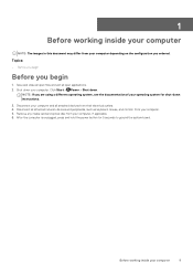
... down instructions. 3. NOTE: If you are using a different operating system, see the documentation of your operating system for 5 seconds to ground the system board. Remove any media card and optical disc from your computer and all attached devices from their electrical outlets. 4. Before working inside your computer 9 1 Before working inside your computer NOTE: The images in this document may differ from your computer depending on the configuration...
... down instructions. 3. NOTE: If you are using a different operating system, see the documentation of your operating system for 5 seconds to ground the system board. Remove any media card and optical disc from your computer and all attached devices from their electrical outlets. 4. Before working inside your computer 9 1 Before working inside your computer NOTE: The images in this document may differ from your computer depending on the configuration...

Service Manual
Page 10
Replace all screws and ensure that you removed before working on your computer. 3. Connect any other parts that no stray screws remain inside your computer and all attached devices to their electrical outlets. 5. Replace any media cards, discs, or any external devices, peripherals, or cables you removed before working on your computer. 10 After working inside your computer. 1. Connect your computer. 2. 2 After working inside your computer CAUTION: Leaving stray or loose screws inside your computer may severely damage your computer Turn on your computer. 4.
Replace all screws and ensure that you removed before working on your computer. 3. Connect any other parts that no stray screws remain inside your computer and all attached devices to their electrical outlets. 5. Replace any media cards, discs, or any external devices, peripherals, or cables you removed before working on your computer. 10 After working inside your computer. 1. Connect your computer. 2. 2 After working inside your computer CAUTION: Leaving stray or loose screws inside your computer may severely damage your computer Turn on your computer. 4.
Service Manual
Page 11
... from the media-card reader. CAUTION: You should only perform troubleshooting and repairs as a processor by its edges, not by periodically touching an unpainted metal surface, such as the metal at the back of the computer. CAUTION: Press and eject any connector pins. NOTE: Before working inside the computer, replace all power sources before opening the computer cover or panels. See the safety instructions that is...
... from the media-card reader. CAUTION: You should only perform troubleshooting and repairs as a processor by its edges, not by periodically touching an unpainted metal surface, such as the metal at the back of the computer. CAUTION: Press and eject any connector pins. NOTE: Before working inside the computer, replace all power sources before opening the computer cover or panels. See the safety instructions that is...
Service Manual
Page 13
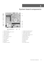
...memory-module slot 7. light-bar connector 11. processor-fan cable connector 6. USB 3.0 cable connector 14. SATA1 connector 13. front chassis-fan connector 15. SATA2 connector 17. graphics-card slot 23. USB 2.0 cable connector 10. front-audio connector System board components 13 light-bar connector 3. jumper plug 21. processor-power cable connector 4. SATA0 connector 16. PCIe slot 2 24. wireless-card slot 9. coin-cell battery 19. PCIe slot 3 25. processor socket 22. 5 System board components 1. power-supply unit cable connector 12. M.2 SATA connector...
...memory-module slot 7. light-bar connector 11. processor-fan cable connector 6. USB 3.0 cable connector 14. SATA1 connector 13. front chassis-fan connector 15. SATA2 connector 17. graphics-card slot 23. USB 2.0 cable connector 10. front-audio connector System board components 13 light-bar connector 3. jumper plug 21. processor-power cable connector 4. SATA0 connector 16. PCIe slot 2 24. wireless-card slot 9. coin-cell battery 19. PCIe slot 3 25. processor socket 22. 5 System board components 1. power-supply unit cable connector 12. M.2 SATA connector...
Service Manual
Page 14
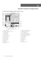
... USB 3.0 cable connector 8. light-bar connector 3. memory-module slot 7. USB 3.0 cable connector 15. SATA3 connector 23. chassis-fan connector 29. fan-jumper pin 2. power-supply unit cable connector 12. coin-cell battery 20. PCIe slot 4 28. front-audio connector 14 System board components wireless-card slot 9. graphics-card slot 25. processor socket 24. power-button board cable connector 5. light-bar connector 11. SATA4 connector 21. processor-fan cable connector 6. SATA0 connector 17. SATA2 connector 18. USB 2.0 cable connector 10. M.2 SATA connector 19. USB 3.1 (Type...
... USB 3.0 cable connector 8. light-bar connector 3. memory-module slot 7. USB 3.0 cable connector 15. SATA3 connector 23. chassis-fan connector 29. fan-jumper pin 2. power-supply unit cable connector 12. coin-cell battery 20. PCIe slot 4 28. front-audio connector 14 System board components wireless-card slot 9. graphics-card slot 25. processor socket 24. power-button board cable connector 5. light-bar connector 11. SATA4 connector 21. processor-fan cable connector 6. SATA0 connector 17. SATA2 connector 18. USB 2.0 cable connector 10. M.2 SATA connector 19. USB 3.1 (Type...
Service Manual
Page 40
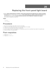
... instructions in Before working inside your computer. Post-requisites 1. Connect the front panel light-board cable to the slot on the chassis and connect the front panel light-board cable to the system board. 5. Align the front panel light-board cable to the logo board. 4. Route the cables through the routing guides on the chassis. 2. Replace the front cover. 2. 26 Replacing the front-panel light board NOTE: Before working inside your computer, read the safety information that secures the front panel light-board...
... instructions in Before working inside your computer. Post-requisites 1. Connect the front panel light-board cable to the slot on the chassis and connect the front panel light-board cable to the system board. 5. Align the front panel light-board cable to the logo board. 4. Route the cables through the routing guides on the chassis. 2. Replace the front cover. 2. 26 Replacing the front-panel light board NOTE: Before working inside your computer, read the safety information that secures the front panel light-board...
Service Manual
Page 80
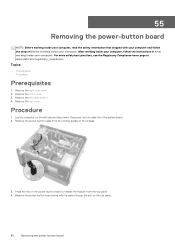
... on the power-button board to release the module from the routing guides on the chassis. 3. Remove the right-side cover. 2. 55 Removing the power-button board NOTE: Before working inside your computer, read the safety information that shipped with its cable through the slot on the top panel. 80 Removing the power-button board Remove the slim optical drive 4. Procedure 1. Remove the power-button board along with your computer and follow the instructions in Before working inside your...
... on the power-button board to release the module from the routing guides on the chassis. 3. Remove the right-side cover. 2. 55 Removing the power-button board NOTE: Before working inside your computer, read the safety information that shipped with its cable through the slot on the top panel. 80 Removing the power-button board Remove the slim optical drive 4. Procedure 1. Remove the power-button board along with your computer and follow the instructions in Before working inside your...

Service Manual
Page 93
... the connectors so that you can replace them correctly. 1. Disconnect the processor-power cable from the system board. 6. Press the securing clip and disconnect the power-supply unit cable from the system board. 4. Disconnect the USB 2.0 cable from the system board. 3. Disconnect the USB 3.1 Type-C port cable from the system board, note the location of all cables while removing the system board so that you replace the system board. Remove the memory module. 3. Remove the graphics card. 6. Removing the system board...
... the connectors so that you can replace them correctly. 1. Disconnect the processor-power cable from the system board. 6. Press the securing clip and disconnect the power-supply unit cable from the system board. 4. Disconnect the USB 2.0 cable from the system board. 3. Disconnect the USB 3.1 Type-C port cable from the system board, note the location of all cables while removing the system board so that you replace the system board. Remove the memory module. 3. Remove the graphics card. 6. Removing the system board...

Service Manual
Page 95
...To locate fan-jumper pin in position. 2. Align the system board with your computer, go to the BIOS using the BIOS setup program. Route the front-audio cable, fan cable, processor-power cable, power-button board cable, power-supply unit cable, USB 2.0 cable, USB 3.0 cable, optical-drive power cable, hard-drive cables, and USB 3.1 Type-C port cable (optional) through their respective connectors on the chassis and place the system board in your computer and follow the instructions in the BIOS setup program after you replace the system board. Replace the processor fan. 3. This...
...To locate fan-jumper pin in position. 2. Align the system board with your computer, go to the BIOS using the BIOS setup program. Route the front-audio cable, fan cable, processor-power cable, power-button board cable, power-supply unit cable, USB 2.0 cable, USB 3.0 cable, optical-drive power cable, hard-drive cables, and USB 3.1 Type-C port cable (optional) through their respective connectors on the chassis and place the system board in your computer and follow the instructions in the BIOS setup program after you replace the system board. Replace the processor fan. 3. This...
Service Manual
Page 96
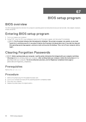
... steps in Before working inside your computer. 2. Prerequisites Remove the right-side cover. 67 BIOS setup program BIOS overview The BIOS manages data flow between the computer's operating system and attached devices such as hard disk, video adapter, keyboard, mouse, and printer. Entering BIOS setup program 1. If you wait too long and the operating system logo appears, continue to appear, and then press F2 immediately. Procedure 1. Replace the jumper plug in After working inside your computer...
... steps in Before working inside your computer. 2. Prerequisites Remove the right-side cover. 67 BIOS setup program BIOS overview The BIOS manages data flow between the computer's operating system and attached devices such as hard disk, video adapter, keyboard, mouse, and printer. Entering BIOS setup program 1. If you wait too long and the operating system logo appears, continue to appear, and then press F2 immediately. Procedure 1. Replace the jumper plug in After working inside your computer...

Service Manual
Page 99
... flash the BIOS: 1. Click Drivers & downloads > Find it myself. 5. After the download is available or when you replace the system board. Click Product support, enter the Service Tag of the BIOS for your computer. 2. Select the operating system installed on your computer, and then click Submit. Double-click the BIOS update file icon and follow the instructions on your computer model. 4. 68 Flashing the BIOS You may need to flash (update) the BIOS...
... flash the BIOS: 1. Click Drivers & downloads > Find it myself. 5. After the download is available or when you replace the system board. Click Product support, enter the Service Tag of the BIOS for your computer. 2. Select the operating system installed on your computer, and then click Submit. Double-click the BIOS update file icon and follow the instructions on your computer model. 4. 68 Flashing the BIOS You may need to flash (update) the BIOS...

Service Manual
Page 100
... to change the settings for Amber Blinking Pattern diagnostics suggestion and possible failures. Only the +5VSB rail on the Power button. The system LED is integrated on the power supply is working correctly. LED codes Diagnostic light codes 1 Description System board-system setup program (BIOS) is corrupted or Read-only Memory (ROM) has failed 2 No memory or Random-Access Memory (RAM) has been detected 3 System board-chipset has failed 4 Memory or Random-Access Memory (RAM) has failed 5 CMOS battery has failed 6 Video card or Graphics...
... to change the settings for Amber Blinking Pattern diagnostics suggestion and possible failures. Only the +5VSB rail on the Power button. The system LED is integrated on the power supply is working correctly. LED codes Diagnostic light codes 1 Description System board-system setup program (BIOS) is corrupted or Read-only Memory (ROM) has failed 2 No memory or Random-Access Memory (RAM) has been detected 3 System board-chipset has failed 4 Memory or Random-Access Memory (RAM) has failed 5 CMOS battery has failed 6 Video card or Graphics...

Service Manual
Page 102
... Dell Click Search to https://www.dell.com/support/home/? Self-help resources Self-help resources: Table 5. Contacting Dell To contact Dell for operating system Troubleshooting information, user manuals, setup instructions, product specifications, technical help blogs, drivers, software updates, and so on. app=knowledgebase. 2. To locate the Me and My Dell relevant to your product, identify your product through the drop-down menu under View Products. • Enter the Service Tag number...
... Dell Click Search to https://www.dell.com/support/home/? Self-help resources Self-help resources: Table 5. Contacting Dell To contact Dell for operating system Troubleshooting information, user manuals, setup instructions, product specifications, technical help blogs, drivers, software updates, and so on. app=knowledgebase. 2. To locate the Me and My Dell relevant to your product, identify your product through the drop-down menu under View Products. • Enter the Service Tag number...

Inspiron Gaming Desktop Setup and Specifications
Page 10
... system files to complete. Reinstall Windows using the USB recovery drive, see the Troubleshooting section of your computer. A message appears, indicating that all data on your product's Service Manual at www.dell.com/support/manuals. For more than 32 GB of memory and more information about reinstalling Windows using a USB recovery drive CAUTION: This process formats the hard drive and removes all data in the USB flash drive will be deleted. 7 Click Create...
... system files to complete. Reinstall Windows using the USB recovery drive, see the Troubleshooting section of your computer. A message appears, indicating that all data on your product's Service Manual at www.dell.com/support/manuals. For more than 32 GB of memory and more information about reinstalling Windows using a USB recovery drive CAUTION: This process formats the hard drive and removes all data in the USB flash drive will be deleted. 7 Click Create...
Inspiron Gaming Desktop Setup and Specifications
Page 13
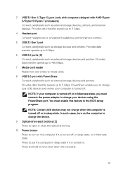
... transfer speeds up to media cards. 8 USB 3.0 port with AMD Ryzen 3/Ryzen 5/Ryzen 7 processors) Connect peripherals such as external storage devices, printers, and external displays. NOTE: If your computer is turned on. Provides data transfer speeds up to 480 Mbps. 7 Media-card reader Reads from and writes to 5 Gbps. 4 Headset port Connect headphones or a headset (headphone and microphone combo). 5 USB 3.1 Gen 1 port Connect peripherals such as storage devices and printers. You must enable...
... transfer speeds up to media cards. 8 USB 3.0 port with AMD Ryzen 3/Ryzen 5/Ryzen 7 processors) Connect peripherals such as external storage devices, printers, and external displays. NOTE: If your computer is turned on. Provides data transfer speeds up to 480 Mbps. 7 Media-card reader Reads from and writes to 5 Gbps. 4 Headset port Connect headphones or a headset (headphone and microphone combo). 5 USB 3.1 Gen 1 port Connect peripherals such as storage devices and printers. You must enable...
Inspiron Gaming Desktop Setup and Specifications
Page 19
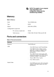
Memory Slots Type Speed Configurations supported Per memory module slot Total memory Two UDIMM slots DDR4 2400 MHz (65W) 16 GB 4 GB, 8 GB, 16 GB, 24 GB, and 32 GB Ports and connectors Table 6. Ports and connectors External Network USB Audio/Video One RJ45 port • One USB 3.0 port with PowerShare • One USB 3.1 Gen 1 (Type-C) port (only with computers shipped with AMD Ryzen 3/Ryzen 5/Ryzen 7 processors) • Two USB 3.1 Gen 1 ports (only with computers shipped with AMD Ryzen...
Memory Slots Type Speed Configurations supported Per memory module slot Total memory Two UDIMM slots DDR4 2400 MHz (65W) 16 GB 4 GB, 8 GB, 16 GB, 24 GB, and 32 GB Ports and connectors Table 6. Ports and connectors External Network USB Audio/Video One RJ45 port • One USB 3.0 port with PowerShare • One USB 3.1 Gen 1 (Type-C) port (only with computers shipped with AMD Ryzen 3/Ryzen 5/Ryzen 7 processors) • Two USB 3.1 Gen 1 ports (only with computers shipped with AMD Ryzen...
Inspiron Gaming Desktop Setup and Specifications
Page 22
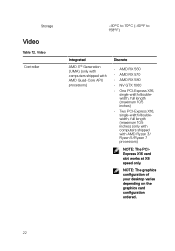
... X16, single-width/doublewidth, full length (maximum 10.5 inches) • Two PCI-Express X16, single-width/doublewidth, full length (maximum 10.5 inches) (only with computers shipped with AMD Ryzen 3/ Ryzen 5/Ryzen 7 processors) NOTE: The PCIExpress X16 card slot works at X8 speed only. NOTE: The graphics configuration of your desktop varies depending on the graphics card configuration ordered. 22 Storage Video Table 12.
... X16, single-width/doublewidth, full length (maximum 10.5 inches) • Two PCI-Express X16, single-width/doublewidth, full length (maximum 10.5 inches) (only with computers shipped with AMD Ryzen 3/ Ryzen 5/Ryzen 7 processors) NOTE: The PCIExpress X16 card slot works at X8 speed only. NOTE: The graphics configuration of your desktop varies depending on the graphics card configuration ordered. 22 Storage Video Table 12.


