Comprehensive Specifications
Page 1
Processor Types Inspiron 560 Inspiron 570 • Intel® Celeron® • Intel Pentium® Dual Core • Intel Core™2 Duo • Intel Core2 Quad • AMD® Sempron&#.../X4 Memory Connectors Memory-module capacities Memory type Memory configurations possible four internally-accessible DDR3 DIMM sockets 1 GB and 2 GB 1066-MHz DDR3 DIMM; Dell™ Inspiron™ 560/570: Comprehensive Specifications This document provides information that you may vary by region. non-ECC memory only 1 GB, 2 GB, 3 GB, 4 GB, 5 GB, 6 GB, 7 GB...
Processor Types Inspiron 560 Inspiron 570 • Intel® Celeron® • Intel Pentium® Dual Core • Intel Core™2 Duo • Intel Core2 Quad • AMD® Sempron&#.../X4 Memory Connectors Memory-module capacities Memory type Memory configurations possible four internally-accessible DDR3 DIMM sockets 1 GB and 2 GB 1066-MHz DDR3 DIMM; Dell™ Inspiron™ 560/570: Comprehensive Specifications This document provides information that you may vary by region. non-ECC memory only 1 GB, 2 GB, 3 GB, 4 GB, 5 GB, 6 GB, 7 GB...
Comprehensive Specifications
Page 2
System Chipset Inspiron 560 Inspiron 570 Drives Externally accessible Internally accessible Video Integrated Inspiron 560 Inspiron 570 Discrete Audio Type System Board Connectors Memory PCI PCI Express x1 PCI Express x16 Power (system board) Processor fan Chassis fan Front USB connector ...
System Chipset Inspiron 560 Inspiron 570 Drives Externally accessible Internally accessible Video Integrated Inspiron 560 Inspiron 570 Discrete Audio Type System Board Connectors Memory PCI PCI Express x1 PCI Express x16 Power (system board) Processor fan Chassis fan Front USB connector ...
Comprehensive Specifications
Page 4
... 149°F) Expansion Slots (continued) PCI Express x1 Connectors two Connector size 36-pin Connector data width (maximum) 1 PCI Express lane Bus speed Inspiron 560 500 MB/s (bi-directional) Inspiron 570 1000 MB/s (bi-directional) Power DC Power Supply Wattage 300 W Maximum heat dissipation 1574 BTU/hr NOTE: Heat dissipation is calculated by...
... 149°F) Expansion Slots (continued) PCI Express x1 Connectors two Connector size 36-pin Connector data width (maximum) 1 PCI Express lane Bus speed Inspiron 560 500 MB/s (bi-directional) Inspiron 570 1000 MB/s (bi-directional) Power DC Power Supply Wattage 300 W Maximum heat dissipation 1574 BTU/hr NOTE: Heat dissipation is calculated by...
Service Manual
Page 1
Dell™ Inspiron™ 560/570 Service Manual Before You Begin Technical Overview Computer Cover Front Bezel Memory Module(s) PCI and PCI Express Cards Drives Fans Front I/O Panel Processor System ... and/or other countries. WARNING: A WARNING indicates a potential for property damage, personal injury, or death. Intel SpeedStep is a trademark of Microsoft Corporation in this text: Dell, the DELL logo, and Inspiron are trademarks of data if instructions are either the entities claiming the marks and names or their products...
Dell™ Inspiron™ 560/570 Service Manual Before You Begin Technical Overview Computer Cover Front Bezel Memory Module(s) PCI and PCI Express Cards Drives Fans Front I/O Panel Processor System ... and/or other countries. WARNING: A WARNING indicates a potential for property damage, personal injury, or death. Intel SpeedStep is a trademark of Microsoft Corporation in this text: Dell, the DELL logo, and Inspiron are trademarks of data if instructions are either the entities claiming the marks and names or their products...
Service Manual
Page 2
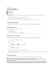
...Instructions Use the following tools: l Small Phillips screwdriver l Small flat-blade screwdriver l BIOS executable update program available at www.dell.com/regulatory_compliance. If your computer: Windows Vista®: Click Start Windows® 7: , click the arrow , and then click.... For additional safety best practices information, see the Comprehensive Specifications at support.dell.com/manuals. Back to Contents Page Before You Begin Dell™ Inspiron™ 560/570 Service Manual Technical Specifications Recommended Tools Turning Off Your Computer Safety Instructions ...
...Instructions Use the following tools: l Small Phillips screwdriver l Small flat-blade screwdriver l BIOS executable update program available at www.dell.com/regulatory_compliance. If your computer: Windows Vista®: Click Start Windows® 7: , click the arrow , and then click.... For additional safety best practices information, see the Comprehensive Specifications at support.dell.com/manuals. Back to Contents Page Before You Begin Dell™ Inspiron™ 560/570 Service Manual Technical Specifications Recommended Tools Turning Off Your Computer Safety Instructions ...
Service Manual
Page 4
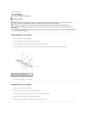
...Replacing the Computer Cover). 5. Set aside the front bezel in Before You Begin. 2. Back to Contents Page Front Bezel Dell™ Inspiron™ 560/570 Service Manual Removing the Front Bezel Replacing the Front Bezel WARNING: Before working inside your computer, read the safety information... that is not authorized by Dell™ is not covered by your warranty. CAUTION: Only a certified service technician should perform ...
...Replacing the Computer Cover). 5. Set aside the front bezel in Before You Begin. 2. Back to Contents Page Front Bezel Dell™ Inspiron™ 560/570 Service Manual Removing the Front Bezel Replacing the Front Bezel WARNING: Before working inside your computer, read the safety information... that is not authorized by Dell™ is not covered by your warranty. CAUTION: Only a certified service technician should perform ...
Service Manual
Page 6
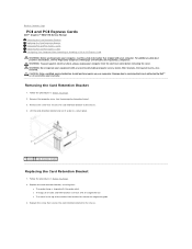
... Computer Cover). 3. Remove the computer cover (see the Regulatory Compliance Homepage at www.dell.com/regulatory_compliance. Replace the card retention bracket, ensuring that: l The guide clamp is not covered by Dell™ is aligned with any cover(s) (including computer covers, bezels, filler brackets, ...that secures the card retention bracket to the chassis. 4. Damage due to Contents Page PCI and PCI Express Cards Dell™ Inspiron™ 560/570 Service Manual Removing the Card Retention Bracket Replacing the Card Retention Bracket Removing PCI and PCI Express Cards Replacing ...
... Computer Cover). 3. Remove the computer cover (see the Regulatory Compliance Homepage at www.dell.com/regulatory_compliance. Replace the card retention bracket, ensuring that: l The guide clamp is not covered by Dell™ is aligned with any cover(s) (including computer covers, bezels, filler brackets, ...that secures the card retention bracket to the chassis. 4. Damage due to Contents Page PCI and PCI Express Cards Dell™ Inspiron™ 560/570 Service Manual Removing the Card Retention Bracket Replacing the Card Retention Bracket Removing PCI and PCI Express Cards Replacing ...
Service Manual
Page 10
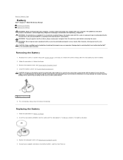
...filler brackets, front-panel inserts, etc.) removed. Follow the procedures in Before You Begin. 3. Back to Contents Page Battery Dell™ Inspiron™ 560/570 Service Manual Removing the Battery Replacing the Battery WARNING: Before working inside your computer, read the safety information that is... not authorized by Dell™ is inserted between the battery and the socket before removing the cover. For additional ...
...filler brackets, front-panel inserts, etc.) removed. Follow the procedures in Before You Begin. 3. Back to Contents Page Battery Dell™ Inspiron™ 560/570 Service Manual Removing the Battery Replacing the Battery WARNING: Before working inside your computer, read the safety information that is... not authorized by Dell™ is inserted between the battery and the socket before removing the cover. For additional ...
Service Manual
Page 12
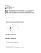
...that secure the computer cover to the chassis. 4. Follow the procedures in Before You Begin. 2. Align the tabs at www.dell.com/regulatory_compliance. CAUTION: Only a certified service technician should perform repairs on its side with the slots located along the edge of ... cover 3 front of the computer. 5. Ensure that is not authorized by Dell™ is seated correctly. 7. Ensure that shipped with your computer. Back to Contents Page Computer Cover Dell™ Inspiron™ 560/570 Service Manual Removing the Computer Cover Replacing the Computer Cover WARNING: Before ...
...that secure the computer cover to the chassis. 4. Follow the procedures in Before You Begin. 2. Align the tabs at www.dell.com/regulatory_compliance. CAUTION: Only a certified service technician should perform repairs on its side with the slots located along the edge of ... cover 3 front of the computer. 5. Ensure that is not authorized by Dell™ is seated correctly. 7. Ensure that shipped with your computer. Back to Contents Page Computer Cover Dell™ Inspiron™ 560/570 Service Manual Removing the Computer Cover Replacing the Computer Cover WARNING: Before ...
Service Manual
Page 14
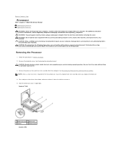
... you replace the processor. 4. For technical service information, see the Regulatory Compliance Homepage at www.dell.com/regulatory_compliance. Back to Contents Page Processor Dell™ Inspiron™ 560/570 Service Manual Removing the Processor Replacing the Processor WARNING: Before working inside your computer, read ...the Processor Fan and Heat Sink Assembly). Damage due to cool before removing the cover. Be sure that is not authorized by Dell is required for the new processor, reuse the original heat sink assembly when you are familiar with your computer. Removing the ...
... you replace the processor. 4. For technical service information, see the Regulatory Compliance Homepage at www.dell.com/regulatory_compliance. Back to Contents Page Processor Dell™ Inspiron™ 560/570 Service Manual Removing the Processor Replacing the Processor WARNING: Before working inside your computer, read ...the Processor Fan and Heat Sink Assembly). Damage due to cool before removing the cover. Be sure that is not authorized by Dell is required for the new processor, reuse the original heat sink assembly when you are familiar with your computer. Removing the ...

Service Manual
Page 15
...seated in the socket, close the processor cover, if applicable. When the processor is positioned underneath the center cover latch on the socket. 8. Inspiron 560 Ensure that the processor is not fully extended, move it to the processor and the computer when you install the processor. 6. Pivot the socket... the release position so that the processor aligns properly with the front and rear alignment-notches on the back of the computer. For Inspiron 560, orient the front and rear alignment-notches on the processor with the socket, and do not use excessive force when you turn on...
...seated in the socket, close the processor cover, if applicable. When the processor is positioned underneath the center cover latch on the socket. 8. Inspiron 560 Ensure that the processor is not fully extended, move it to the processor and the computer when you install the processor. 6. Pivot the socket... the release position so that the processor aligns properly with the front and rear alignment-notches on the back of the computer. For Inspiron 560, orient the front and rear alignment-notches on the processor with the socket, and do not use excessive force when you turn on...

Service Manual
Page 17
...Follow the procedures in Before You Begin. 2. Follow the procedures in Before You Begin. 2. Back to Contents Page Drives Dell™ Inspiron™ 560/570 Service Manual Hard Drive Media Card Reader Optical Drive WARNING: Before working inside your computer, read the safety information that... the hard drive's circuit board, while removing or replacing the hard drive. 5. Remove the four screws that it is not covered by Dell™ is configured for your warranty. Replacing the Hard Drive 1. CAUTION: Only a certified service technician should perform repairs on your computer ...
...Follow the procedures in Before You Begin. 2. Follow the procedures in Before You Begin. 2. Back to Contents Page Drives Dell™ Inspiron™ 560/570 Service Manual Hard Drive Media Card Reader Optical Drive WARNING: Before working inside your computer, read the safety information that... the hard drive's circuit board, while removing or replacing the hard drive. 5. Remove the four screws that it is not covered by Dell™ is configured for your warranty. Replacing the Hard Drive 1. CAUTION: Only a certified service technician should perform repairs on your computer ...
Service Manual
Page 21
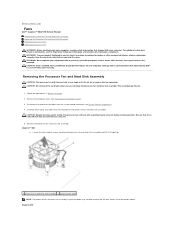
...covered by your warranty. Carefully move away any cover(s) (including computer covers, bezels, filler brackets, front-panel inserts, etc.) removed. Inspiron™ 560 a. CAUTION: Only a certified service technician should perform repairs on your computer may be very hot during normal operation. This could damage...processor fan and heat sink assembly may not look exactly like the one single unit. Back to Contents Page Fans Dell™ Inspiron™ 560/570 Service Manual Removing the Processor Fan and Heat Sink Assembly Replacing the Processor Fan and Heat Sink Assembly Removing...
...covered by your warranty. Carefully move away any cover(s) (including computer covers, bezels, filler brackets, front-panel inserts, etc.) removed. Inspiron™ 560 a. CAUTION: Only a certified service technician should perform repairs on your computer may be very hot during normal operation. This could damage...processor fan and heat sink assembly may not look exactly like the one single unit. Back to Contents Page Fans Dell™ Inspiron™ 560/570 Service Manual Removing the Processor Fan and Heat Sink Assembly Replacing the Processor Fan and Heat Sink Assembly Removing...

Service Manual
Page 22
...Rotate the clamp lever 180 degrees counter-clockwise to the four metal screw-hole projections on its top, with the two bracket projections. b. Inspiron 570 a. Connect your computer may not look exactly like the one shown in the illustration above. New thermal grease is critical for ensuring ...Hold the processor fan and heat sink fan assembly in your computer and devices to secure the processor fan and heat sink assembly. 4. a. Inspiron 560 a. c. Replace the computer cover (see System Board Components). 5. CAUTION: Ensure that you do not pinch the wires that the two clamp ...
...Rotate the clamp lever 180 degrees counter-clockwise to the four metal screw-hole projections on its top, with the two bracket projections. b. Inspiron 570 a. Connect your computer may not look exactly like the one shown in the illustration above. New thermal grease is critical for ensuring ...Hold the processor fan and heat sink fan assembly in your computer and devices to secure the processor fan and heat sink assembly. 4. a. Inspiron 560 a. c. Replace the computer cover (see System Board Components). 5. CAUTION: Ensure that you do not pinch the wires that the two clamp ...
Service Manual
Page 24
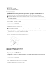
...servicing that you disconnected from the system board connectors. 3. Remove the computer cover (see the Regulatory Compliance Homepage at www.dell.com/regulatory_compliance. Remove the front bezel (see Removing the Front Bezel). CAUTION: Only a certified service technician should perform repairs...Note the routing of all the cables that secures the front I/O panel to the chassis. 6. Back to Contents Page Front I/O Panel Dell™ Inspiron™ 560/570 Service Manual Removing the Front I/O Panel Replacing the Front I /O panel out of the computer, be extremely careful. Removing the ...
...servicing that you disconnected from the system board connectors. 3. Remove the computer cover (see the Regulatory Compliance Homepage at www.dell.com/regulatory_compliance. Remove the front bezel (see Removing the Front Bezel). CAUTION: Only a certified service technician should perform repairs...Note the routing of all the cables that secures the front I/O panel to the chassis. 6. Back to Contents Page Front I/O Panel Dell™ Inspiron™ 560/570 Service Manual Removing the Front I/O Panel Replacing the Front I /O panel out of the computer, be extremely careful. Removing the ...
Service Manual
Page 26
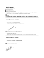
...Follow the procedures in Before You Begin. 2. CAUTION: Do not install ECC memory modules. 4. If the memory module is not covered by Dell™ is difficult to remove, gently ease the memory module back and forth to remove it upwards. Press out the securing clip at each... end of the memory module with the tab in Before You Begin. 2. Back to Contents Page Memory Module(s) Dell™ Inspiron™ 560/570 Service Manual Removing the Memory Module(s) Replacing the Memory Module(s) Recommended Memory Configuration Setting Up Dual-Channel Memory Configuration WARNING: ...
...Follow the procedures in Before You Begin. 2. CAUTION: Do not install ECC memory modules. 4. If the memory module is not covered by Dell™ is difficult to remove, gently ease the memory module back and forth to remove it upwards. Press out the securing clip at each... end of the memory module with the tab in Before You Begin. 2. Back to Contents Page Memory Module(s) Dell™ Inspiron™ 560/570 Service Manual Removing the Memory Module(s) Replacing the Memory Module(s) Recommended Memory Configuration Setting Up Dual-Channel Memory Configuration WARNING: ...

Service Manual
Page 27
... modules DIMM1 DIMM3 DIMM2 DIMM4 DIMM3 DIMM4 DIMM3 DIMM2 Four modules DIMM1 DIMM3 DIMM2 DIMM4 DIMM4 DIMM3 DIMM2 DIMM1 Setting Up Dual-Channel Memory Configuration Inspiron 560 If you apply equal force to the table below. Replace the computer cover (see System Board Components. Log on your computer and devices to continue...
... modules DIMM1 DIMM3 DIMM2 DIMM4 DIMM3 DIMM4 DIMM3 DIMM2 Four modules DIMM1 DIMM3 DIMM2 DIMM4 DIMM4 DIMM3 DIMM2 DIMM1 Setting Up Dual-Channel Memory Configuration Inspiron 560 If you apply equal force to the table below. Replace the computer cover (see System Board Components. Log on your computer and devices to continue...
Service Manual
Page 29
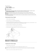
... Failure to replace and tighten all the cables from the securing clip on your computer. Back to Contents Page Power Supply Dell™ Inspiron™ 560/570 Service Manual Removing the Power Supply Replacing the Power Supply WARNING: Before working inside your computer, read the safety information...bezels, filler brackets, front-panel inserts, etc.) removed. While pressing down on www.dell.com at the following location: www.dell.com/regulatory_compliance. Replace the four screws that is not authorized by Dell™ is not covered by your computer from the system board and the drives....
... Failure to replace and tighten all the cables from the securing clip on your computer. Back to Contents Page Power Supply Dell™ Inspiron™ 560/570 Service Manual Removing the Power Supply Replacing the Power Supply WARNING: Before working inside your computer, read the safety information...bezels, filler brackets, front-panel inserts, etc.) removed. While pressing down on www.dell.com at the following location: www.dell.com/regulatory_compliance. Replace the four screws that is not authorized by Dell™ is not covered by your computer from the system board and the drives....
Service Manual
Page 31
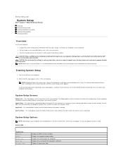
...hardware, power conservation, and security features. When the DELL logo appears, press immediately. NOTE: Keyboard failure may not appear exactly as the user password. Use the right- System Setup Screens Options List - Inspiron 560 System Info BIOS Info System Service Tag Asset Tag... devices, the items listed in this field you can cause your warranty. Back to Contents Page System Setup Dell™ Inspiron™ 560/570 Service Manual Overview Entering System Setup Clearing Forgotten Passwords Clearing CMOS Settings Flashing the BIOS Overview Use System Setup...
...hardware, power conservation, and security features. When the DELL logo appears, press immediately. NOTE: Keyboard failure may not appear exactly as the user password. Use the right- System Setup Screens Options List - Inspiron 560 System Info BIOS Info System Service Tag Asset Tag... devices, the items listed in this field you can cause your warranty. Back to Contents Page System Setup Dell™ Inspiron™ 560/570 Service Manual Overview Entering System Setup Clearing Forgotten Passwords Clearing CMOS Settings Flashing the BIOS Overview Use System Setup...

Service Manual
Page 35
... Before You Begin. 2. Locate the 3-pin password reset jumper on the system. If required, press and hold the power button to enable the password feature. 7. Inspiron 560 Inspiron 570 4. Replace the computer cover (see Removing the Computer Cover). 3. NOTE: The location of the password connector may vary depending on the system board (see...
... Before You Begin. 2. Locate the 3-pin password reset jumper on the system. If required, press and hold the power button to enable the password feature. 7. Inspiron 560 Inspiron 570 4. Replace the computer cover (see Removing the Computer Cover). 3. NOTE: The location of the password connector may vary depending on the system board (see...


