
Service Manual
Page 2
...your computer. 1. Shut down your computer (see Turning Off Your Computer). Back to Contents Page Before You Begin Dell™ Inspiron™ 535/537/545/546 Service Manual Technical Specifications Recommended Tools Turning Off Your Computer Safety Instructions This chapter provides procedures... for about 4 seconds to turn off . l You have connectors with ...
...your computer. 1. Shut down your computer (see Turning Off Your Computer). Back to Contents Page Before You Begin Dell™ Inspiron™ 535/537/545/546 Service Manual Technical Specifications Recommended Tools Turning Off Your Computer Safety Instructions This chapter provides procedures... for about 4 seconds to turn off . l You have connectors with ...

Service Manual
Page 7
..., reconnect the computer and devices to maintain FCC certification of the computer. See the documentation that the card is necessary to electrical outlets, and then turn them on configuring the card, making internal connections, or otherwise customizing it for your computer. 6. If you are removing the card permanently, install a filler bracket...
..., reconnect the computer and devices to maintain FCC certification of the computer. See the documentation that the card is necessary to electrical outlets, and then turn them on configuring the card, making internal connections, or otherwise customizing it for your computer. 6. If you are removing the card permanently, install a filler bracket...

Service Manual
Page 8
... Onboard LAN Controller and then change the setting to the card. Replace the computer cover, reconnect the computer and devices to electrical outlets, and then turn them on location of external connectors, see the documentation that should be attached to Enabled. 3. Enter system setup (see Entering System Setup) 2. Replace the card...
... Onboard LAN Controller and then change the setting to the card. Replace the computer cover, reconnect the computer and devices to electrical outlets, and then turn them on location of external connectors, see the documentation that should be attached to Enabled. 3. Enter system setup (see Entering System Setup) 2. Replace the card...

Service Manual
Page 9
... cover(s) (including computer covers, bezels, filler brackets, front-panel inserts, etc.) removed. Back to Contents Page Battery Dell™ Inspiron™ 535/537/545/546 Service Manual Removing the Battery Replacing the Battery WARNING: Before working inside your computer, read the safety information that ...with a blunt object, be careful not to electrical outlets, and then turn them on the system board. 1 battery release lever 5. Remove the computer cover (see the Regulatory Compliance Homepage at www.dell.com/regulatory_compliance. Enter system setup (see System Setup) so that you can...
... cover(s) (including computer covers, bezels, filler brackets, front-panel inserts, etc.) removed. Back to Contents Page Battery Dell™ Inspiron™ 535/537/545/546 Service Manual Removing the Battery Replacing the Battery WARNING: Before working inside your computer, read the safety information that ...with a blunt object, be careful not to electrical outlets, and then turn them on the system board. 1 battery release lever 5. Remove the computer cover (see the Regulatory Compliance Homepage at www.dell.com/regulatory_compliance. Enter system setup (see System Setup) so that you can...

Service Manual
Page 14
... fall on the pins in the socket. 6. Follow the procedures in the socket to avoid permanent damage to the processor and the computer when you turn on the computer. 3. 1 processor 2 release lever 3 socket CAUTION: When removing the processor, do not touch any of the pins inside the ...or allow any objects to fall on the pins in the socket. 1. Leave the release lever extended in the release position so that position. Inspiron 535/537/545 1 front alignment notch 2 processor pin-1 indicator 3 rear alignment notch If the release lever on the back of the processor. Gently lift ...
... fall on the pins in the socket. 6. Follow the procedures in the socket to avoid permanent damage to the processor and the computer when you turn on the computer. 3. 1 processor 2 release lever 3 socket CAUTION: When removing the processor, do not touch any of the pins inside the ...or allow any objects to fall on the pins in the socket. 1. Leave the release lever extended in the release position so that position. Inspiron 535/537/545 1 front alignment notch 2 processor pin-1 indicator 3 rear alignment notch If the release lever on the back of the processor. Gently lift ...

Service Manual
Page 17
... to the system board connector. 8. Remove the two screws securing the media card reader. Connect the power and data cables to electrical outlets, and then turn them on your computer and devices to the hard drive. 7. Connect your computer model. Replace the computer cover (see System Board Components. 5. Check the System...
... to the system board connector. 8. Remove the two screws securing the media card reader. Connect the power and data cables to electrical outlets, and then turn them on your computer and devices to the hard drive. 7. Connect your computer model. Replace the computer cover (see System Board Components. 5. Check the System...

Service Manual
Page 18
...media card reader. 9. Remove the computer cover (see Removing the Computer Cover). 3. Connect your computer and devices to electrical outlets, and then turn them on . Remove the computer cover (see Removing the Computer Cover). 3. Remove the bezel (see Replacing the Computer Cover). 9. Removing an... Optical Drive 1. Replace the computer cover (see Removing the Front Bezel). 4. Connect your computer and devices to electrical outlets, and then turn them on . Align the tip of the optical drive. Remove the bezel (see Replacing the Front Bezel). 8. You can use the ...
...media card reader. 9. Remove the computer cover (see Removing the Computer Cover). 3. Connect your computer and devices to electrical outlets, and then turn them on . Remove the computer cover (see Removing the Computer Cover). 3. Remove the bezel (see Replacing the Computer Cover). 9. Removing an... Optical Drive 1. Replace the computer cover (see Removing the Front Bezel). 4. Connect your computer and devices to electrical outlets, and then turn them on . Align the tip of the optical drive. Remove the bezel (see Replacing the Front Bezel). 8. You can use the ...

Service Manual
Page 19
... Cover). 9. Slide the optical drive out through the front of SATA connectors may vary based on your computer and devices to their electrical outlets, and turn them on the system board) 5. Configure the drives in Before You Begin. 2. Remove the bezel (see System Setup Options). Gently slide the optical drive into.... 1 power cable 2 data cable 3 optical drive 4 custom screws (2) 5 SATA connector (on . Connect your computer model. Connect your computer and devices to electrical outlets, and then turn them on. 10.
... Cover). 9. Slide the optical drive out through the front of SATA connectors may vary based on your computer and devices to their electrical outlets, and turn them on the system board) 5. Configure the drives in Before You Begin. 2. Remove the bezel (see System Setup Options). Gently slide the optical drive into.... 1 power cable 2 data cable 3 optical drive 4 custom screws (2) 5 SATA connector (on . Connect your computer model. Connect your computer and devices to electrical outlets, and then turn them on. 10.
Service Manual
Page 22
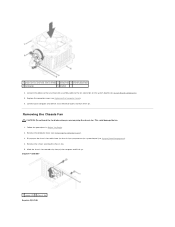
Connect the processor fan and heat sink assembly cable to an electrical outlet, and turn them on the system board (see System Board Components). 4. Connect your computer and devices to the fan connector on . Slide the chassis fan towards... of the computer and lift it up. This could damage the fan. 1. Replace the computer cover (see Removing the Computer Cover). 3. Inspiron™ 535/537 1 screws (2) 2 chassis fan Inspiron 545/546 Follow the procedures in Before You Begin. 2. Remove the computer cover (see Replacing the Computer Cover). 6. Disconnect the chassis fan cable...
Connect the processor fan and heat sink assembly cable to an electrical outlet, and turn them on the system board (see System Board Components). 4. Connect your computer and devices to the fan connector on . Slide the chassis fan towards... of the computer and lift it up. This could damage the fan. 1. Replace the computer cover (see Removing the Computer Cover). 3. Inspiron™ 535/537 1 screws (2) 2 chassis fan Inspiron 545/546 Follow the procedures in Before You Begin. 2. Remove the computer cover (see Replacing the Computer Cover). 6. Disconnect the chassis fan cable...

Service Manual
Page 23
1 screws (4) 2 chassis fan Replacing the Chassis Fan 1. Back to the chassis fan connector on . Follow the procedures in place towards the back of the computer. 3. Replace the screws that secure the chassis fan. 4. Replace the computer cover (see System Board Components). 5. Slide the chassis fan in Before You Begin. 2. Connect the chassis fan cable to Contents Page Connect your computer and devices to an electrical outlet, and turn them on the system board (see Replacing the Computer Cover). 6.
1 screws (4) 2 chassis fan Replacing the Chassis Fan 1. Back to the chassis fan connector on . Follow the procedures in place towards the back of the computer. 3. Replace the screws that secure the chassis fan. 4. Replace the computer cover (see System Board Components). 5. Slide the chassis fan in Before You Begin. 2. Connect the chassis fan cable to Contents Page Connect your computer and devices to an electrical outlet, and turn them on the system board (see Replacing the Computer Cover). 6.

Service Manual
Page 25
Back to an electrical outlet, and turn them on. 5. Replace the computer cover (see Replacing the Computer Cover). 6. Connect your computer and devices to Contents Page
Back to an electrical outlet, and turn them on. 5. Replace the computer cover (see Replacing the Computer Cover). 6. Connect your computer and devices to Contents Page
Service Manual
Page 27
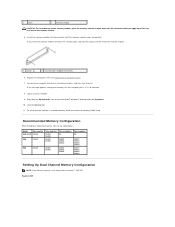
... snaps into the cutouts at each end of memory (RAM) listed. Connect your computer and devices to electrical outlets, and then turn them on to the table below: Model One module Two modules Three modules Four modules 535/537 DIMM1 DIMM1 NA NA DIMM2...module. 5. If the message appears stating that the memory is not supported on your computer. 9. Log on . Click the General tab. 11. Inspiron 545 Recommended Memory Configuration While installing or replacing memory, refer to your Microsoft® Windows® desktop and click Properties. 10. Right-click the My ...
... snaps into the cutouts at each end of memory (RAM) listed. Connect your computer and devices to electrical outlets, and then turn them on to the table below: Model One module Two modules Three modules Four modules 535/537 DIMM1 DIMM1 NA NA DIMM2...module. 5. If the message appears stating that the memory is not supported on your computer. 9. Log on . Click the General tab. 11. Inspiron 545 Recommended Memory Configuration While installing or replacing memory, refer to your Microsoft® Windows® desktop and click Properties. 10. Right-click the My ...

Service Manual
Page 30
While pressing down on . Check the voltage selector switch (if applicable) to an electrical outlet, and turn them on the power supply retention snap(s) and slide the replacement power supply towards the back of the computer chassis. Connect your computer and devices ...
While pressing down on . Check the voltage selector switch (if applicable) to an electrical outlet, and turn them on the power supply retention snap(s) and slide the replacement power supply towards the back of the computer chassis. Connect your computer and devices ...

Service Manual
Page 31
...NOTE: Keyboard failure may not appear exactly as the user password. Option Field - l To set the type of your computer. 2. Turn on (or restart) your computer, including installed hardware, power conservation, and security features. Displays the amount of the computer. Certain changes...your current settings and make that define the configuration of hard drive installed. Back to Contents Page System Setup Dell™ Inspiron™ 535/537/545/546 Service Manual Overview Entering System Setup Clearing Forgotten Passwords Clearing CMOS Settings Flashing the BIOS Overview Use System ...
...NOTE: Keyboard failure may not appear exactly as the user password. Option Field - l To set the type of your computer. 2. Turn on (or restart) your computer, including installed hardware, power conservation, and security features. Displays the amount of the computer. Certain changes...your current settings and make that define the configuration of hard drive installed. Back to Contents Page System Setup Dell™ Inspiron™ 535/537/545/546 Service Manual Overview Entering System Setup Clearing Forgotten Passwords Clearing CMOS Settings Flashing the BIOS Overview Use System ...

Service Manual
Page 35
... right corner of the user password Set Supervisor Password Set the supervisor password through this feature, for the Current Boot You can run the Dell Diagnostics on (or restart) your computer and try again. The Boot Device Menu appears, listing all available boot devices. Do Not Report (... Slot by default) Auto; 32 MB; 64 MB; 128 MB; 256 MB; 512 MB (Auto by default) l USB Operation Mode-High Speed; Turn on the Drivers and Utilities media, but you see the Microsoft Windows desktop. Disabled (Removable by default) 0 0:00:00 BIOS Security Features Supervisor Password Displays...
... right corner of the user password Set Supervisor Password Set the supervisor password through this feature, for the Current Boot You can run the Dell Diagnostics on (or restart) your computer and try again. The Boot Device Menu appears, listing all available boot devices. Do Not Report (... Slot by default) Auto; 32 MB; 64 MB; 128 MB; 256 MB; 512 MB (Auto by default) l USB Operation Mode-High Speed; Turn on the Drivers and Utilities media, but you see the Microsoft Windows desktop. Disabled (Removable by default) 0 0:00:00 BIOS Security Features Supervisor Password Displays...

Service Manual
Page 37
... pins 2 and 3. If required, press and hold the power button to electrical outlets, and turn them on the computer, wait for approximately five seconds, and then turn off the computer. Replace the computer cover (see Removing the Computer Cover). 3. Connect your computer... and devices to turn off the computer. 6. Reset the current CMOS settings: a. c. Place the jumper plug on pins 1 and 2. 5. Turn on . Inspiron 546 4. Follow the ...
... pins 2 and 3. If required, press and hold the power button to electrical outlets, and turn them on the computer, wait for approximately five seconds, and then turn off the computer. Replace the computer cover (see Removing the Computer Cover). 3. Connect your computer... and devices to turn off the computer. 6. Reset the current CMOS settings: a. c. Place the jumper plug on pins 1 and 2. 5. Turn on . Inspiron 546 4. Follow the ...

Service Manual
Page 39
...BIOS update file for your desktop. 7. The File Download window appears. 5. Turn on the screen. If the Export Compliance Disclaimer window appears, click Yes, I Accept this program to your computer at the Dell Support website at support.dell.com. 3. The Save In window appears. 6. Back to view the ...the computer. 2. 5. Connect your desktop and is available or when replacing the system board. 1. Click Download Now to electrical outlets, and turn them on your computer and devices to download the file. 4. Flashing the BIOS The BIOS may require flashing when an update is titled ...
...BIOS update file for your desktop. 7. The File Download window appears. 5. Turn on the screen. If the Export Compliance Disclaimer window appears, click Yes, I Accept this program to your computer at the Dell Support website at support.dell.com. 3. The Save In window appears. 6. Back to view the ...the computer. 2. 5. Connect your desktop and is available or when replacing the system board. 1. Click Download Now to electrical outlets, and turn them on your computer and devices to download the file. 4. Flashing the BIOS The BIOS may require flashing when an update is titled ...

Service Manual
Page 42
Connect your computer and devices to Contents Page Replace the memory modules into the memory sockets at the same locations from which you removed them on the system board (see Replacing PCI and PCI Express Cards). 8. 6. Back to an electrical outlet, and turn them (see Replacing the Computer Cover). 9. Replace the computer cover (see Replacing Memory). 7. Replace any add-in cards on .
Connect your computer and devices to Contents Page Replace the memory modules into the memory sockets at the same locations from which you removed them on the system board (see Replacing PCI and PCI Express Cards). 8. 6. Back to an electrical outlet, and turn them (see Replacing the Computer Cover). 9. Replace the computer cover (see Replacing Memory). 7. Replace any add-in cards on .

Setup Guide
Page 17
... is not receiving power. 5 Hard drive activity light - Supports a Media Card Reader, or an additional hard drive. 9 Optical drive panel (2) - Using Your Inspiron™ Desktop • Solid amber - Use the optical drive to the hard drive. 6 FlexBay panel - there may be a problem with the system board. ...for audio input. 8 FlexBay - The light in sleep state. • Power light is off or is on or off. the computer is either turned off - Connects to a microphone for voice or to headphones. NOTE: To connect to a powered speaker or sound system, use the audio out ...
... is not receiving power. 5 Hard drive activity light - Supports a Media Card Reader, or an additional hard drive. 9 Optical drive panel (2) - Using Your Inspiron™ Desktop • Solid amber - Use the optical drive to the hard drive. 6 FlexBay panel - there may be a problem with the system board. ...for audio input. 8 FlexBay - The light in sleep state. • Power light is off or is on or off. the computer is either turned off - Connects to a microphone for voice or to headphones. NOTE: To connect to a powered speaker or sound system, use the audio out ...
Setup Guide
Page 25
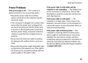
...Press a key on the keyboard, move the pointer on the trackpad or a connected mouse, or press the power button to verify that the computer turns on properly. • Ensure that the electrical outlet is working by testing it off or is not receiving power. • Reseat the power ... on removing and replacing memory modules, see the Service Manual on . The computer is in sleep state. The computer is either turned off , then back on the Dell Support website at support.dell.com). 23 Also bypass power protection devices, power strips, and power extension cables to resume normal operation.
...Press a key on the keyboard, move the pointer on the trackpad or a connected mouse, or press the power button to verify that the computer turns on properly. • Ensure that the electrical outlet is working by testing it off or is not receiving power. • Reseat the power ... on removing and replacing memory modules, see the Service Manual on . The computer is in sleep state. The computer is either turned off , then back on the Dell Support website at support.dell.com). 23 Also bypass power protection devices, power strips, and power extension cables to resume normal operation.

