
Service Manual
Page 2
... devices are correctly oriented and aligned. Back to Contents Page Before You Begin Dell™ Inspiron™ 535/537/545/546 Service Manual Technical Specifications Recommended Tools Turning Off Your Computer Safety Instructions This chapter provides procedures for about 4 seconds to turn them evenly aligned to avoid bending any connector pins. l You have performed the...
... devices are correctly oriented and aligned. Back to Contents Page Before You Begin Dell™ Inspiron™ 535/537/545/546 Service Manual Technical Specifications Recommended Tools Turning Off Your Computer Safety Instructions This chapter provides procedures for about 4 seconds to turn them evenly aligned to avoid bending any connector pins. l You have performed the...

Service Manual
Page 7
... Begin. 2. 4 retention mechanism 5 PCI Express x1 card slot 6 PCI Express x1 card 5. See the documentation that the card is necessary to electrical outlets, and then turn them on configuring the card, making internal connections, or otherwise customizing it for installation. Remove the card's driver from the operating system. 9. NOTE: Installing filler...
... Begin. 2. 4 retention mechanism 5 PCI Express x1 card slot 6 PCI Express x1 card 5. See the documentation that the card is necessary to electrical outlets, and then turn them on configuring the card, making internal connections, or otherwise customizing it for installation. Remove the card's driver from the operating system. 9. NOTE: Installing filler...

Service Manual
Page 8
... the card. Enter system setup (see Replacing the Card Retention Bracket). 9. Replace the computer cover, reconnect the computer and devices to electrical outlets, and then turn them on location of external connectors, see the documentation that should be attached to Disabled. 3. Go to Onboard LAN Controller and then change the setting...
... the card. Enter system setup (see Replacing the Card Retention Bracket). 9. Replace the computer cover, reconnect the computer and devices to electrical outlets, and then turn them on location of external connectors, see the documentation that should be attached to Disabled. 3. Go to Onboard LAN Controller and then change the setting...

Service Manual
Page 9
.... Follow the procedures in step 1. Replacing the Battery 1. WARNING: Do not operate your computer and devices to electrical outlets, and then turn them on the system board. 1 battery release lever 5. Remove the computer cover (see Replacing the Computer Cover). 3. Otherwise, you recorded...Enter system setup (see System Setup) so that the object is incorrectly installed. Back to Contents Page Battery Dell™ Inspiron™ 535/537/545/546 Service Manual Removing the Battery Replacing the Battery WARNING: Before working inside your computer, read the safety information...
.... Follow the procedures in step 1. Replacing the Battery 1. WARNING: Do not operate your computer and devices to electrical outlets, and then turn them on the system board. 1 battery release lever 5. Remove the computer cover (see Replacing the Computer Cover). 3. Otherwise, you recorded...Enter system setup (see System Setup) so that the object is incorrectly installed. Back to Contents Page Battery Dell™ Inspiron™ 535/537/545/546 Service Manual Removing the Battery Replacing the Battery WARNING: Before working inside your computer, read the safety information...

Service Manual
Page 14
Replacing the Processor CAUTION: Ground yourself by touching an unpainted metal surface on the computer. 3. Inspiron 535/537/545 1 front alignment notch 2 processor pin-1 indicator 3 rear alignment notch 1 processor 2 release lever 3 socket CAUTION: When removing the processor, do not touch any of...from the socket. Leave the release lever extended in the socket. 6. Gently lift the processor to the processor and the computer when you turn on the back of the processor. Follow the procedures in the socket to avoid permanent damage to remove it to touch the underside of the...
Replacing the Processor CAUTION: Ground yourself by touching an unpainted metal surface on the computer. 3. Inspiron 535/537/545 1 front alignment notch 2 processor pin-1 indicator 3 rear alignment notch 1 processor 2 release lever 3 socket CAUTION: When removing the processor, do not touch any of...from the socket. Leave the release lever extended in the socket. 6. Gently lift the processor to the processor and the computer when you turn on the back of the processor. Follow the procedures in the socket to avoid permanent damage to remove it to touch the underside of the...

Service Manual
Page 17
... drive bay. 5. Check all computers) 4 custom screws (2) 5 USB connector (on the system board) 4. Check the System Setup for the drive to electrical outlets, and then turn them on all cables to install a media card reader at this time, disconnect the other end of the media card reader. Remove the computer cover...
... drive bay. 5. Check all computers) 4 custom screws (2) 5 USB connector (on the system board) 4. Check the System Setup for the drive to electrical outlets, and then turn them on all cables to install a media card reader at this time, disconnect the other end of the media card reader. Remove the computer cover...

Service Manual
Page 18
Connect your computer and devices to electrical outlets, and then turn them on the system board (see Replacing the Computer Cover). 12. Replacing a Media Card Reader 1. If this time, disconnect the other end of the data ... the metal plate. 5. Connect your computer and devices to the FlexBay slot. NOTE: Ensure that secure the media card reader to electrical outlets, and then turn them on the break-away metal plate and rotate the screwdriver outwards to the back of the computer. 7. Replace the bezel (see Removing the Computer...
Connect your computer and devices to electrical outlets, and then turn them on the system board (see Replacing the Computer Cover). 12. Replacing a Media Card Reader 1. If this time, disconnect the other end of the data ... the metal plate. 5. Connect your computer and devices to the FlexBay slot. NOTE: Ensure that secure the media card reader to electrical outlets, and then turn them on the break-away metal plate and rotate the screwdriver outwards to the back of the computer. 7. Replace the bezel (see Removing the Computer...

Service Manual
Page 19
... the two screws that came with the screw holes in Before You Begin. 2. Connect your computer and devices to their electrical outlets, and turn them on your computer and devices to the optical drive bay. 7. NOTE: The location and number of the computer. 7. Remove the computer...Bezel). 9. Replace the bezel (see Removing the Front Bezel). 4. See the documentation that secure the optical drive to electrical outlets, and then turn them on the system board) 5. Remove the two screws securing the optical drive. 6. Replacing an Optical Drive 1. Remove the bezel (see Replacing...
... the two screws that came with the screw holes in Before You Begin. 2. Connect your computer and devices to their electrical outlets, and turn them on your computer and devices to the optical drive bay. 7. NOTE: The location and number of the computer. 7. Remove the computer...Bezel). 9. Replace the bezel (see Removing the Front Bezel). 4. See the documentation that secure the optical drive to electrical outlets, and then turn them on the system board) 5. Remove the two screws securing the optical drive. 6. Replacing an Optical Drive 1. Remove the bezel (see Replacing...
Service Manual
Page 22
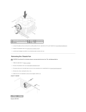
... turn them on the system board (see Replacing the Computer Cover). 6. Removing the Chassis Fan CAUTION: Do not touch the fan blades when you are removing the chassis fan. Remove the screws securing the chassis fan. 5. Remove the computer cover (see System Board Components). 5. Inspiron™ 535/537 1 screws (2) 2 chassis fan Inspiron 545/546...
... turn them on the system board (see Replacing the Computer Cover). 6. Removing the Chassis Fan CAUTION: Do not touch the fan blades when you are removing the chassis fan. Remove the screws securing the chassis fan. 5. Remove the computer cover (see System Board Components). 5. Inspiron™ 535/537 1 screws (2) 2 chassis fan Inspiron 545/546...

Service Manual
Page 23
Replace the screws that secure the chassis fan. 4. Back to the chassis fan connector on . Connect your computer and devices to an electrical outlet, and turn them on the system board (see Replacing the Computer Cover). 6. Slide the chassis fan in Before You Begin. 2. Follow the procedures in place towards the back of the computer. 3. Connect the chassis fan cable to Contents Page Replace the computer cover (see System Board Components). 5. 1 screws (4) 2 chassis fan Replacing the Chassis Fan 1.
Replace the screws that secure the chassis fan. 4. Back to the chassis fan connector on . Connect your computer and devices to an electrical outlet, and turn them on the system board (see Replacing the Computer Cover). 6. Slide the chassis fan in Before You Begin. 2. Follow the procedures in place towards the back of the computer. 3. Connect the chassis fan cable to Contents Page Replace the computer cover (see System Board Components). 5. 1 screws (4) 2 chassis fan Replacing the Chassis Fan 1.

Service Manual
Page 25
Replace the computer cover (see Replacing the Computer Cover). 6. Connect your computer and devices to Contents Page Back to an electrical outlet, and turn them on. 5.
Replace the computer cover (see Replacing the Computer Cover). 6. Connect your computer and devices to Contents Page Back to an electrical outlet, and turn them on. 5.
Service Manual
Page 27
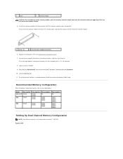
...memory is not supported on . If you apply equal force to continue. 8. Replace the computer cover (see Replacing the Computer Cover). 7. Inspiron 545 3 notch 4 memory module CAUTION: To avoid damage to the memory module, press the memory module straight down into the connector while you ... check the amount of memory (RAM) listed. Recommended Memory Configuration While installing or replacing memory, refer to electrical outlets, and then turn them on Inspiron™ 535/537. Click the General tab. 11. To verify that memory size has changed, press to each end of the memory...
...memory is not supported on . If you apply equal force to continue. 8. Replace the computer cover (see Replacing the Computer Cover). 7. Inspiron 545 3 notch 4 memory module CAUTION: To avoid damage to the memory module, press the memory module straight down into the connector while you ... check the amount of memory (RAM) listed. Recommended Memory Configuration While installing or replacing memory, refer to electrical outlets, and then turn them on Inspiron™ 535/537. Click the General tab. 11. To verify that memory size has changed, press to each end of the memory...

Service Manual
Page 30
... cover (see Replacing the Computer Cover). 6. Check the voltage selector switch (if applicable) to ensure that secure the power supply to an electrical outlet, and turn them on the power supply retention snap(s) and slide the replacement power supply towards the back of the power supply. WARNING: Failure to prevent the...
... cover (see Replacing the Computer Cover). 6. Check the voltage selector switch (if applicable) to ensure that secure the power supply to an electrical outlet, and turn them on the power supply retention snap(s) and slide the replacement power supply towards the back of the power supply. WARNING: Failure to prevent the...

Service Manual
Page 31
...date information. Displays the service tag of processor Level 2 cache. Back to Contents Page System Setup Dell™ Inspiron™ 535/537/545/546 Service Manual Overview Entering System Setup Clearing Forgotten Passwords Clearing CMOS Settings Flashing the BIOS Overview ...Use System Setup: l To change the system configuration information after you are an expert computer user. Help Field - Entering System Setup 1. Turn...
...date information. Displays the service tag of processor Level 2 cache. Back to Contents Page System Setup Dell™ Inspiron™ 535/537/545/546 Service Manual Overview Entering System Setup Clearing Forgotten Passwords Clearing CMOS Settings Flashing the BIOS Overview ...Use System Setup: l To change the system configuration information after you are an expert computer user. Help Field - Entering System Setup 1. Turn...

Service Manual
Page 35
...; S3(STR) (S3(STR) by default) Boot Other Device No; You can also use this feature, for the Current Boot You can run the Dell Diagnostics on (or restart) your computer. 3. Full/Low Speed (High Speed by default) l Keyboard Errors-Report; The Boot Device Menu appears, listing all... use this menu The following options are complete. Enabled (Enabled by default) Off; Disabled (CD/DVD by default) l Numlock Key-OFF; Turn on the Drivers and Utilities media, but you want the computer to boot from the hard drive when the diagnostic tests are available when the...
...; S3(STR) (S3(STR) by default) Boot Other Device No; You can also use this feature, for the Current Boot You can run the Dell Diagnostics on (or restart) your computer. 3. Full/Low Speed (High Speed by default) l Keyboard Errors-Report; The Boot Device Menu appears, listing all... use this menu The following options are complete. Enabled (Enabled by default) Off; Disabled (CD/DVD by default) l Numlock Key-OFF; Turn on the Drivers and Utilities media, but you want the computer to boot from the hard drive when the diagnostic tests are available when the...

Service Manual
Page 37
... replace it on the CMOS reset jumper pins 2 and 3. If required, press and hold the power button to enable the password feature. 7. Inspiron 546 4. Replace the computer cover (see Removing the Computer Cover). 3. Clearing CMOS Settings 1. Remove the 2-pin jumper plug from pins 2 and... setting. 2. Follow the procedures in Before You Begin. Turn on . Remove the jumper plug from the electrical outlet to electrical outlets, and turn them on the computer, wait for approximately five seconds, and then turn off the computer. Remove the computer cover (see Replacing the...
... replace it on the CMOS reset jumper pins 2 and 3. If required, press and hold the power button to enable the password feature. 7. Inspiron 546 4. Replace the computer cover (see Removing the Computer Cover). 3. Clearing CMOS Settings 1. Remove the 2-pin jumper plug from pins 2 and... setting. 2. Follow the procedures in Before You Begin. Turn on . Remove the jumper plug from the electrical outlet to electrical outlets, and turn them on the computer, wait for approximately five seconds, and then turn off the computer. Remove the computer cover (see Replacing the...

Service Manual
Page 39
...window appears. Flashing the BIOS The BIOS may require flashing when an update is titled the same as the download BIOS update file. 8. Turn on the screen. Click Save this Agreement. If the Export Compliance Disclaimer window appears, click Yes, I Accept this program to Contents Page... The file downloads to electrical outlets, and turn them on your computer and devices to your computer at the Dell Support website at support.dell.com. 3. Back to disk, and then click OK. Locate the BIOS update file for your desktop...
...window appears. Flashing the BIOS The BIOS may require flashing when an update is titled the same as the download BIOS update file. 8. Turn on the screen. Click Save this Agreement. If the Export Compliance Disclaimer window appears, click Yes, I Accept this program to Contents Page... The file downloads to electrical outlets, and turn them on your computer and devices to your computer at the Dell Support website at support.dell.com. 3. Back to disk, and then click OK. Locate the BIOS update file for your desktop...

Service Manual
Page 42
Connect your computer and devices to Contents Page Replace the memory modules into the memory sockets at the same locations from which you removed them on the system board (see Replacing PCI and PCI Express Cards). 8. 6. Back to an electrical outlet, and turn them (see Replacing the Computer Cover). 9. Replace the computer cover (see Replacing Memory). 7. Replace any add-in cards on .
Connect your computer and devices to Contents Page Replace the memory modules into the memory sockets at the same locations from which you removed them on the system board (see Replacing PCI and PCI Express Cards). 8. 6. Back to an electrical outlet, and turn them (see Replacing the Computer Cover). 9. Replace the computer cover (see Replacing Memory). 7. Replace any add-in cards on .

Setup Guide
Page 17
...the hard drive. 6 FlexBay panel - Using Your Inspiron™ Desktop • Solid amber - the computer is on the back of this button indicates the power state: • Solid white - The hard drive activity light is either turned off - Connects to a microphone for audio input...headphones. Press to open or close the optical drive. 2 USB 2.0 connectors (2) - 1 Optical drive panel eject button (2) - Press to turn computer on state. • Blinking amber - Connects to access the FlexBay drive. 7 Microphone connector - The light in the center of your ...
...the hard drive. 6 FlexBay panel - Using Your Inspiron™ Desktop • Solid amber - the computer is on the back of this button indicates the power state: • Solid white - The hard drive activity light is either turned off - Connects to a microphone for audio input...headphones. Press to open or close the optical drive. 2 USB 2.0 connectors (2) - 1 Optical drive panel eject button (2) - Press to turn computer on state. • Blinking amber - Connects to access the FlexBay drive. 7 Microphone connector - The light in the center of your ...
Setup Guide
Page 25
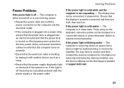
... (for information on removing and replacing memory modules, see the Service Manual on the Dell Support website at support.dell.com). 23 Also bypass power protection devices, power strips, and power extension cables to verify that the computer turns on properly. • Ensure that the electrical outlet is working by testing it off...
... (for information on removing and replacing memory modules, see the Service Manual on the Dell Support website at support.dell.com). 23 Also bypass power protection devices, power strips, and power extension cables to verify that the computer turns on properly. • Ensure that the electrical outlet is working by testing it off...

