Service Manual
Page 2
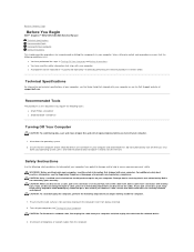
... components in your computer or see the Dell Support website at www.dell.com/regulatory_compliance. Back to Contents Page Before You Begin Dell™ Inspiron™ 535/537/545/546 Service Manual Technical Specifications Recommended Tools Turning Off Your Computer Safety Instructions This chapter ...provides procedures for about 4 seconds to turn off your computer from being scratched. 2. ...
... components in your computer or see the Dell Support website at www.dell.com/regulatory_compliance. Back to Contents Page Before You Begin Dell™ Inspiron™ 535/537/545/546 Service Manual Technical Specifications Recommended Tools Turning Off Your Computer Safety Instructions This chapter ...provides procedures for about 4 seconds to turn off your computer from being scratched. 2. ...
Service Manual
Page 7
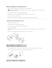
..., position the card so the securing slot is fully seated in Before You Begin. 2. Ensure that the card is necessary to electrical outlets, and then turn them on configuring the card, making internal connections, or otherwise customizing it for your computer. 6. NOTE: Installing filler brackets over empty card-slot openings is...
..., position the card so the securing slot is fully seated in Before You Begin. 2. Ensure that the card is necessary to electrical outlets, and then turn them on configuring the card, making internal connections, or otherwise customizing it for your computer. 6. NOTE: Installing filler brackets over empty card-slot openings is...
Service Manual
Page 8
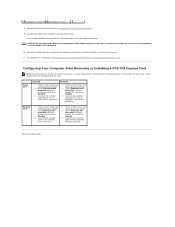
...'s connectors. 1. For information on installing drivers and software for information about the card's cable connections. Connect the external audio devices to electrical outlets, and then turn them on location of external connectors, see Entering System Setup) 2. Enter system setup (see the Setup Guide. Go to Onboard LAN Controller and then change...
...'s connectors. 1. For information on installing drivers and software for information about the card's cable connections. Connect the external audio devices to electrical outlets, and then turn them on location of external connectors, see Entering System Setup) 2. Enter system setup (see the Setup Guide. Go to Onboard LAN Controller and then change...
Service Manual
Page 9
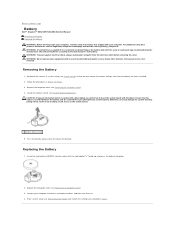
...Computer Cover). 4. WARNING: Do not operate your computer from the electrical outlet before you attempt to Contents Page Battery Dell™ Inspiron™ 535/537/545/546 Service Manual Removing the Battery Replacing the Battery WARNING: Before working inside your computer, read the safety information ... the same or equivalent type recommended by breaking circuit traces on . 4. Press the battery release lever to electrical outlets, and then turn them on the system board. 1 battery release lever 5. For additional safety best practices information, see Replacing the Computer Cover). 3....
...Computer Cover). 4. WARNING: Do not operate your computer from the electrical outlet before you attempt to Contents Page Battery Dell™ Inspiron™ 535/537/545/546 Service Manual Removing the Battery Replacing the Battery WARNING: Before working inside your computer, read the safety information ... the same or equivalent type recommended by breaking circuit traces on . 4. Press the battery release lever to electrical outlets, and then turn them on the system board. 1 battery release lever 5. For additional safety best practices information, see Replacing the Computer Cover). 3....
Service Manual
Page 14
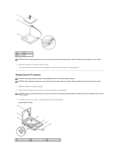
Inspiron 535/537/545 1 front alignment notch 2 processor pin-1 indicator 3 rear alignment notch Replacing the Processor CAUTION: Ground yourself by touching an unpainted metal surface on the back ... in the release position so that position. Follow the procedures in the socket to avoid permanent damage to the processor and the computer when you turn on the computer. 3. 1 processor 2 release lever 3 socket CAUTION: When removing the processor, do not touch any of the pins inside the socket or allow any...
Inspiron 535/537/545 1 front alignment notch 2 processor pin-1 indicator 3 rear alignment notch Replacing the Processor CAUTION: Ground yourself by touching an unpainted metal surface on the back ... in the release position so that position. Follow the procedures in the socket to avoid permanent damage to the processor and the computer when you turn on the computer. 3. 1 processor 2 release lever 3 socket CAUTION: When removing the processor, do not touch any of the pins inside the socket or allow any...
Service Manual
Page 17
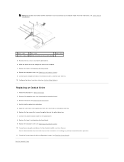
... properly connected and firmly seated. 9. Slide the hard drive into the hard drive bay. 5. Connect the power and data cables to electrical outlets, and then turn them on installing any software required for drive operation. 12. Check all computers) 4 custom screws (2) 5 USB connector (on your computer. 4. Check the System Setup for...
... properly connected and firmly seated. 9. Slide the hard drive into the hard drive bay. 5. Connect the power and data cables to electrical outlets, and then turn them on installing any software required for drive operation. 12. Check all computers) 4 custom screws (2) 5 USB connector (on your computer. 4. Check the System Setup for...
Service Manual
Page 18
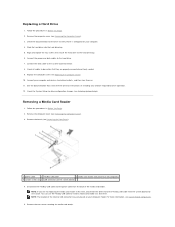
...metal plate. 5. Remove the bezel (see Removing the Computer Cover). 3. NOTE: Ensure that secure the media card reader to electrical outlets, and then turn them on . Replace the bezel (see Replacing the Front Bezel). 8. Replace the bezel (see Replacing the Front Bezel). 11. Replacing a Media ...FlexBay USB cable to the internal USB connector on the break-away metal plate and rotate the screwdriver outwards to electrical outlets, and then turn them on . Follow the procedures in Before You Begin. 2. Remove the computer cover (see Replacing the Computer Cover). 9. NOTE: ...
...metal plate. 5. Remove the bezel (see Removing the Computer Cover). 3. NOTE: Ensure that secure the media card reader to electrical outlets, and then turn them on . Replace the bezel (see Replacing the Front Bezel). 8. Replace the bezel (see Replacing the Front Bezel). 11. Replacing a Media ...FlexBay USB cable to the internal USB connector on the break-away metal plate and rotate the screwdriver outwards to electrical outlets, and then turn them on . Follow the procedures in Before You Begin. 2. Remove the computer cover (see Replacing the Computer Cover). 9. NOTE: ...
Service Manual
Page 19
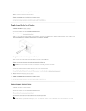
...the optical drive into place. 5. Connect the power and data cables to Contents Page Connect your computer and devices to their electrical outlets, and turn them on . 10. Replace the bezel (see Replacing the Front Bezel). 9. Align the screw holes in Before You Begin. 2. Remove ... for drive configuration changes (see Replacing the Computer Cover). 9. Connect your computer and devices to electrical outlets, and then turn them on . Remove the computer cover (see Replacing the Computer Cover). 10. Replace the computer cover (see Removing the Computer Cover). 3.
...the optical drive into place. 5. Connect the power and data cables to Contents Page Connect your computer and devices to their electrical outlets, and turn them on . 10. Replace the bezel (see Replacing the Front Bezel). 9. Align the screw holes in Before You Begin. 2. Remove ... for drive configuration changes (see Replacing the Computer Cover). 9. Connect your computer and devices to electrical outlets, and then turn them on . Remove the computer cover (see Replacing the Computer Cover). 10. Replace the computer cover (see Removing the Computer Cover). 3.
Service Manual
Page 22
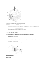
...damage the fan. 1. Disconnect the chassis fan cable from the chassis fan connector on the system board (see Replacing the Computer Cover). 6. Inspiron™ 535/537 1 screws (2) 2 chassis fan Inspiron 545/546 Replace the computer cover (see System Board Components). 4. Follow the procedures in Before You Begin. 2. Remove the computer cover (see...sink assembly 2 clamp lever 3 bracket projection 4 clamp grip 5 bracket 4. Connect the processor fan and heat sink assembly cable to an electrical outlet, and turn them on the system board (see Removing the Computer Cover). 3.
...damage the fan. 1. Disconnect the chassis fan cable from the chassis fan connector on the system board (see Replacing the Computer Cover). 6. Inspiron™ 535/537 1 screws (2) 2 chassis fan Inspiron 545/546 Replace the computer cover (see System Board Components). 4. Follow the procedures in Before You Begin. 2. Remove the computer cover (see...sink assembly 2 clamp lever 3 bracket projection 4 clamp grip 5 bracket 4. Connect the processor fan and heat sink assembly cable to an electrical outlet, and turn them on the system board (see Removing the Computer Cover). 3.
Service Manual
Page 23
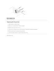
Back to an electrical outlet, and turn them on the system board (see Replacing the Computer Cover). 6. Connect the chassis fan cable to the chassis fan connector on . Follow the procedures in place towards the back of the computer. 3. Slide the chassis fan in Before You Begin. 2. Connect your computer and devices to Contents Page Replace the screws that secure the chassis fan. 4. 1 screws (4) 2 chassis fan Replacing the Chassis Fan 1. Replace the computer cover (see System Board Components). 5.
Back to an electrical outlet, and turn them on the system board (see Replacing the Computer Cover). 6. Connect the chassis fan cable to the chassis fan connector on . Follow the procedures in place towards the back of the computer. 3. Slide the chassis fan in Before You Begin. 2. Connect your computer and devices to Contents Page Replace the screws that secure the chassis fan. 4. 1 screws (4) 2 chassis fan Replacing the Chassis Fan 1. Replace the computer cover (see System Board Components). 5.

Service Manual
Page 25
Connect your computer and devices to Contents Page Replace the computer cover (see Replacing the Computer Cover). 6. Back to an electrical outlet, and turn them on. 5.
Connect your computer and devices to Contents Page Replace the computer cover (see Replacing the Computer Cover). 6. Back to an electrical outlet, and turn them on. 5.
Service Manual
Page 27
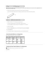
...that memory size has changed, press to continue. 8. If the message appears stating that the memory is not supported on Inspiron™ 535/537. Inspiron 545 Replace the computer cover (see Replacing the Computer Cover). 7. Log on to your computer and devices to electrical outlets, ...and then turn them on your Microsoft® Windows® desktop and click Properties. 10. Right-click the My Computer icon on . Click...
...that memory size has changed, press to continue. 8. If the message appears stating that the memory is not supported on Inspiron™ 535/537. Inspiron 545 Replace the computer cover (see Replacing the Computer Cover). 7. Log on to your computer and devices to electrical outlets, ...and then turn them on your Microsoft® Windows® desktop and click Properties. 10. Right-click the My Computer icon on . Click...
Service Manual
Page 30
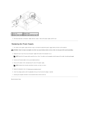
... the computer chassis. Back to prevent the cables from being damaged. 3. WARNING: Failure to replace and tighten all cable connections to an electrical outlet, and turn them on the power supply retention snap(s), slide out the power supply and lift it out. The cables must be properly routed to Contents Page...
... the computer chassis. Back to prevent the cables from being damaged. 3. WARNING: Failure to replace and tighten all cable connections to an electrical outlet, and turn them on the power supply retention snap(s), slide out the power supply and lift it out. The cables must be properly routed to Contents Page...
Service Manual
Page 31
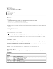
...your settings. Displays the asset tag for extended periods of the system setup window. Back to Contents Page System Setup Dell™ Inspiron™ 535/537/545/546 Service Manual Overview Entering System Setup Clearing Forgotten Passwords Clearing CMOS Settings Flashing the BIOS Overview Use System Setup...release in this field you see the Microsoft® Windows® desktop, then shut down for the computer, if present. Turn on your computer and installed devices, the items listed in even intervals until you can cause your computer. and left-arrow keys...
...your settings. Displays the asset tag for extended periods of the system setup window. Back to Contents Page System Setup Dell™ Inspiron™ 535/537/545/546 Service Manual Overview Entering System Setup Clearing Forgotten Passwords Clearing CMOS Settings Flashing the BIOS Overview Use System Setup...release in this field you see the Microsoft® Windows® desktop, then shut down for the computer, if present. Turn on your computer and installed devices, the items listed in even intervals until you can cause your computer. and left-arrow keys...
Service Manual
Page 35
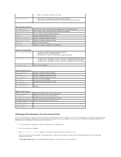
...Disabled; Do Not Report (Report by default) RAID; CD/DVD; You can also use this feature, for the Current Boot You can run the Dell Diagnostics on (or restart) your computer. 3. right corner of the user password Set Supervisor Password Set the supervisor password through this menu The following ...Display First UMA Frame Buffer Size Onboard Audio Controller HD Audio Onboard LAN Controller Onboard LAN Boot ROM SATA Mode Module Bay PCI-E 16X Slot; Turn on the Drivers and Utilities media, but you are booting to a USB device, connect the USB device to boot from the hard drive ...
...Disabled; Do Not Report (Report by default) RAID; CD/DVD; You can also use this feature, for the Current Boot You can run the Dell Diagnostics on (or restart) your computer. 3. right corner of the user password Set Supervisor Password Set the supervisor password through this menu The following ...Display First UMA Frame Buffer Size Onboard Audio Controller HD Audio Onboard LAN Controller Onboard LAN Boot ROM SATA Mode Module Bay PCI-E 16X Slot; Turn on the Drivers and Utilities media, but you are booting to a USB device, connect the USB device to boot from the hard drive ...
Service Manual
Page 37
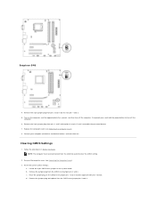
...from pins 2 and 3 and fix it on the computer, wait for approximately five seconds, and then turn off the computer. 6. Remove the computer cover (see Replacing the Computer Cover). 8. b. Place the ... Locate the 3-pin CMOS reset jumper on the CMOS reset jumper pins 1 and 2 and wait approximately five seconds. Turn on pins 2 and 3 to clear the CMOS setting. 2. Reset the current CMOS settings: a. Replace the computer ... plug from the electrical outlet to enable the password feature. 7. Inspiron 546 4. Remove the 2-pin jumper plug from the CMOS reset jumper pins 2 and 3.
...from pins 2 and 3 and fix it on the computer, wait for approximately five seconds, and then turn off the computer. 6. Remove the computer cover (see Replacing the Computer Cover). 8. b. Place the ... Locate the 3-pin CMOS reset jumper on the CMOS reset jumper pins 1 and 2 and wait approximately five seconds. Turn on pins 2 and 3 to clear the CMOS setting. 2. Reset the current CMOS settings: a. Replace the computer ... plug from the electrical outlet to enable the password feature. 7. Inspiron 546 4. Remove the 2-pin jumper plug from the CMOS reset jumper pins 2 and 3.
Service Manual
Page 39
... BIOS update file. 8. If the Export Compliance Disclaimer window appears, click Yes, I Accept this program to your computer at the Dell Support website at support.dell.com. 3. The Save In window appears. 6. Connect your desktop and is available or when replacing the system board. 1. Double-... Download Now to view the Save In menu, select Desktop, and then click Save. Click Save this Agreement. Back to electrical outlets, and turn them on your computer and devices to Contents Page The file icon appears on . The File Download window appears. 5. Click Close when the ...
... BIOS update file. 8. If the Export Compliance Disclaimer window appears, click Yes, I Accept this program to your computer at the Dell Support website at support.dell.com. 3. The Save In window appears. 6. Connect your desktop and is available or when replacing the system board. 1. Double-... Download Now to view the Save In menu, select Desktop, and then click Save. Click Save this Agreement. Back to electrical outlets, and turn them on your computer and devices to Contents Page The file icon appears on . The File Download window appears. 5. Click Close when the ...

Service Manual
Page 42
Replace the computer cover (see Replacing Memory). 7. Connect your computer and devices to Contents Page Back to an electrical outlet, and turn them (see Replacing the Computer Cover). 9. Replace the memory modules into the memory sockets at the same locations from which you removed them on the system board (see Replacing PCI and PCI Express Cards). 8. Replace any add-in cards on . 6.
Replace the computer cover (see Replacing Memory). 7. Connect your computer and devices to Contents Page Back to an electrical outlet, and turn them (see Replacing the Computer Cover). 9. Replace the memory modules into the memory sockets at the same locations from which you removed them on the system board (see Replacing PCI and PCI Express Cards). 8. Replace any add-in cards on . 6.
Setup Guide
Page 17
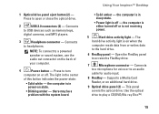
...use the audio out connector on when the computer reads data from or writes data to access the FlexBay drive. 7 Microphone connector - Press to turn computer on state. • Blinking amber - the computer is not receiving power. 5 Hard drive activity light - Supports a Media Card Reader,.... 9 Optical drive panel (2) - The light in power-on or off or is either turned off . NOTE: To connect to play a CD/DVD/Blu-ray Disc™. 15 the computer is off - Using Your Inspiron™ Desktop • Solid amber - 1 Optical drive panel eject button (2) - Connects to...
...use the audio out connector on when the computer reads data from or writes data to access the FlexBay drive. 7 Microphone connector - Press to turn computer on state. • Blinking amber - the computer is not receiving power. 5 Hard drive activity light - Supports a Media Card Reader,.... 9 Optical drive panel (2) - The light in power-on or off or is either turned off . NOTE: To connect to play a CD/DVD/Blu-ray Disc™. 15 the computer is off - Using Your Inspiron™ Desktop • Solid amber - 1 Optical drive panel eject button (2) - Connects to...
Setup Guide
Page 25
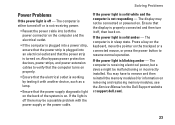
...(for information on removing and replacing memory modules, see the Service Manual on the Dell Support website at support.dell.com). 23 The computer is blinking amber - Ensure that the display is properly connected and then turn it with the power supply or the power cable. The computer is either... turned off - Solving Problems Power Problems If the power light is off or is not receiving ...
...(for information on removing and replacing memory modules, see the Service Manual on the Dell Support website at support.dell.com). 23 The computer is blinking amber - Ensure that the display is properly connected and then turn it with the power supply or the power cable. The computer is either... turned off - Solving Problems Power Problems If the power light is off or is not receiving ...


