Owner's Manual
Page 18
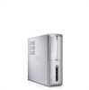
For more information). 2 card slots Access connectors for any installed PCI and PCI Express cards. 3 power supply LED Indicates power availability for attaching a commercially available theft-deterrent device. NOTE: May ... to the inside of the computer. To use the padlock rings, insert a commercially available padlock through the rings, and then lock the padlock. 7 security cable slot Security cable slot lets you to secure the computer cover to the chassis with the device. 18 Setting Up and Using Your Computer
For more information). 2 card slots Access connectors for any installed PCI and PCI Express cards. 3 power supply LED Indicates power availability for attaching a commercially available theft-deterrent device. NOTE: May ... to the inside of the computer. To use the padlock rings, insert a commercially available padlock through the rings, and then lock the padlock. 7 security cable slot Security cable slot lets you to secure the computer cover to the chassis with the device. 18 Setting Up and Using Your Computer
Owner's Manual
Page 32
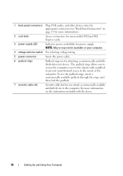
1 2 3 4 1 xD-Picture Card and SmartMedia (SMC) 3 Memory Stick (MS/MS Pro) 2 CompactFlash Type I and II (CF I/II) and MicroDrive Card 4 SecureDigital Card (SD)/ MultiMediaCard (MMC) To use the Media Card Reader: 1 Check the media or card to determine the proper orientation for insertion. 2 Slide the media or card into the appropriate slot until it is completely seated in the connector. Check the card orientation and try again. 32 Setting Up and Using Your Computer If you encounter resistance, do not force the media or card.
1 2 3 4 1 xD-Picture Card and SmartMedia (SMC) 3 Memory Stick (MS/MS Pro) 2 CompactFlash Type I and II (CF I/II) and MicroDrive Card 4 SecureDigital Card (SD)/ MultiMediaCard (MMC) To use the Media Card Reader: 1 Check the media or card to determine the proper orientation for insertion. 2 Slide the media or card into the appropriate slot until it is completely seated in the connector. Check the card orientation and try again. 32 Setting Up and Using Your Computer If you encounter resistance, do not force the media or card.
Owner's Manual
Page 36
Because hibernate mode requires a special file on your hard drive with enough disk space to store the contents of the computer memory, Dell creates an appropriately sized hibernate mode file before shipping the computer to exit from standby mode, press a key on the Power Schemes ... corrupted, Windows XP recreates the hibernate file automatically. 36 Setting Up and Using Your Computer When there is installed in the PCI Express x16 slot. To set standby mode to a reserved area on the Power Schemes Tab and Advanced Tab. Hibernate Mode Hibernate mode conserves power by . ...
Because hibernate mode requires a special file on your hard drive with enough disk space to store the contents of the computer memory, Dell creates an appropriately sized hibernate mode file before shipping the computer to exit from standby mode, press a key on the Power Schemes ... corrupted, Windows XP recreates the hibernate file automatically. 36 Setting Up and Using Your Computer When there is installed in the PCI Express x16 slot. To set standby mode to a reserved area on the Power Schemes Tab and Advanced Tab. Hibernate Mode Hibernate mode conserves power by . ...
Owner's Manual
Page 66
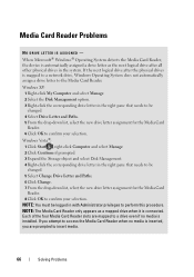
... the Media Card Reader when no media is connected. Media Card Reader Problems NO DRIVE LETTER IS ASSIGNED - Each of the four Media Card Reader slots are prompted to a drive even if no media is inserted, you are mapped to insert media. 66 Solving Problems
... the Media Card Reader when no media is connected. Media Card Reader Problems NO DRIVE LETTER IS ASSIGNED - Each of the four Media Card Reader slots are prompted to a drive even if no media is inserted, you are mapped to insert media. 66 Solving Problems

Owner's Manual
Page 116
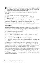
... metal surface on the computer chassis.Your Dell™ computer provides the following slots for PCI and PCI Express cards: • One PCI Express x16 card slot (SLOT1) • One PCI Express x1 card slot (SLOT2) • Two PCI card slots (SLOT3, SLOT4) See "System Board Components...page 116). Cards CAUTION: Before you begin any of your body before you are replacing a card, remove the current driver for card slot location. NOTICE: To prevent static damage to components inside your computer, discharge static electricity from the operating system. 116 Removing and Installing ...
... metal surface on the computer chassis.Your Dell™ computer provides the following slots for PCI and PCI Express cards: • One PCI Express x16 card slot (SLOT1) • One PCI Express x1 card slot (SLOT2) • Two PCI card slots (SLOT3, SLOT4) See "System Board Components...page 116). Cards CAUTION: Before you begin any of your body before you are replacing a card, remove the current driver for card slot location. NOTICE: To prevent static damage to components inside your computer, discharge static electricity from the operating system. 116 Removing and Installing ...
Owner's Manual
Page 118
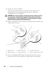
... computer from the electrical outlet before installing any cards. 8 Place the card in the slot. 3 4 2 5 6 1 1 alignment bar 2 fully-seated card 3 not fully-seated card 4 alignment guide 5 bracket within slot 6 bracket caught outside of slot 9 If you are connected to a network.To guard against electrical shock, laceration by... when they are installing the PCI Express card into the x16 card connector, position the card so the securing slot is fully seated in the connector and press down firmly. Ensure that came with the securing tab. 118 Removing and Installing Parts
... computer from the electrical outlet before installing any cards. 8 Place the card in the slot. 3 4 2 5 6 1 1 alignment bar 2 fully-seated card 3 not fully-seated card 4 alignment guide 5 bracket within slot 6 bracket caught outside of slot 9 If you are connected to a network.To guard against electrical shock, laceration by... when they are installing the PCI Express card into the x16 card connector, position the card so the securing slot is fully seated in the connector and press down firmly. Ensure that came with the securing tab. 118 Removing and Installing Parts
Owner's Manual
Page 119
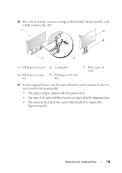
... card or filler bracket fits around the alignment guide. Ensure that the card is fully seated in the slot. 1 3 4 5 2 1 PCI Express x16 card 2 securing tab 4 PCI Express x1 card slot 5 PCI Express x16 card slot 3 PCI Express x1 card 11 Fix the support bracket and then press down the card retention bracket to... seat it on its slot ensuring that: • The guide clamp is aligned with the guide notch. • The tops of all cards and filler brackets are flush with the ...
... card or filler bracket fits around the alignment guide. Ensure that the card is fully seated in the slot. 1 3 4 5 2 1 PCI Express x16 card 2 securing tab 4 PCI Express x1 card slot 5 PCI Express x16 card slot 3 PCI Express x1 card 11 Fix the support bracket and then press down the card retention bracket to... seat it on its slot ensuring that: • The guide clamp is aligned with the guide notch. • The tops of all cards and filler brackets are flush with the ...
Owner's Manual
Page 120
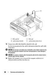
... to the equipment. See the documentation for the card for information about the card's cable connections. Cables routed over or behind the cards. 4 3 2 1 1 PCI card slot 3 card retention bracket 2 PCI card 4 card retention release lever 12 Connect any cables that should be attached to electrical outlets, and then turn them on...
... to the equipment. See the documentation for the card for information about the card's cable connections. Cables routed over or behind the cards. 4 3 2 1 1 PCI card slot 3 card retention bracket 2 PCI card 4 card retention release lever 12 Connect any cables that should be attached to electrical outlets, and then turn them on...
Owner's Manual
Page 122
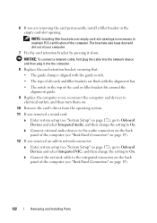
... change the setting to maintain FCC certification of all cards and filler brackets are removing the card permanently, install a filler bracket in the empty card-slot opening. b Connect external audio devices to On. NOTICE: To connect a network cable, first plug the cable into the computer. 8 Replace the card retention bracket, ensuring...add-in network connector: a Enter system setup (see "System Setup" on page 19). 122 Removing and Installing Parts NOTE: Installing filler brackets over empty card-slot openings is aligned with the guide notch. • The tops of the computer.
... change the setting to maintain FCC certification of all cards and filler brackets are removing the card permanently, install a filler bracket in the empty card-slot opening. b Connect external audio devices to On. NOTICE: To connect a network cable, first plug the cable into the computer. 8 Replace the card retention bracket, ensuring...add-in network connector: a Enter system setup (see "System Setup" on page 19). 122 Removing and Installing Parts NOTE: Installing filler brackets over empty card-slot openings is aligned with the guide notch. • The tops of the computer.
Owner's Manual
Page 131
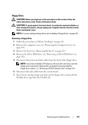
... the floppy drive. CAUTION: To guard against electrical shock, laceration by moving fan blades, or other unexpected injuries, always unplug your computer from the FlexBay slot. Removing a Floppy Drive 1 Follow the procedures in the Product Information Guide.
... the floppy drive. CAUTION: To guard against electrical shock, laceration by moving fan blades, or other unexpected injuries, always unplug your computer from the FlexBay slot. Removing a Floppy Drive 1 Follow the procedures in the Product Information Guide.
Owner's Manual
Page 133
... the two spring clamps and slide out the FlexBay drive cage from the FlexBay drive cage. 10 Slide the FlexBay drive cage in the FlexBay slot till it towards the cage notch to align the cage notch with the notch holes in "Before You Begin" on page 101. 2 Remove the computer...
... the two spring clamps and slide out the FlexBay drive cage from the FlexBay drive cage. 10 Slide the FlexBay drive cage in the FlexBay slot till it towards the cage notch to align the cage notch with the notch holes in "Before You Begin" on page 101. 2 Remove the computer...
Owner's Manual
Page 134
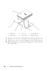
1 2 3 4 6 5 1 floppy drive 4 notch hole (2) 2 screws (2) 3 spring clamp (2) 5 cage notch (2) 6 floppy drive cage 8 Align the two screw holes on the floppy drive with the FlexBay drive cage. 9 Tighten the two screws to secure the floppy drive in the FlexBay drive cage. 10 Slide the FlexBay drive cage along with the floppy drive in the FlexBay slot till it snaps in place. 134 Removing and Installing Parts
1 2 3 4 6 5 1 floppy drive 4 notch hole (2) 2 screws (2) 3 spring clamp (2) 5 cage notch (2) 6 floppy drive cage 8 Align the two screw holes on the floppy drive with the FlexBay drive cage. 9 Tighten the two screws to secure the floppy drive in the FlexBay drive cage. 10 Slide the FlexBay drive cage along with the floppy drive in the FlexBay slot till it snaps in place. 134 Removing and Installing Parts
Owner's Manual
Page 137
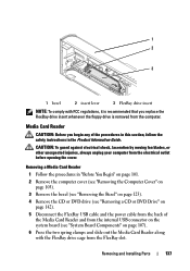
... Installing Parts 137 CAUTION: To guard against electrical shock, laceration by moving fan blades, or other unexpected injuries, always unplug your computer from the FlexBay slot. 1 2 3 1 bezel 2 insert lever 3 FlexBay drive insert NOTE: To comply with FCC regulations, it is recommended that you begin any of the Media Card Reader and...
... Installing Parts 137 CAUTION: To guard against electrical shock, laceration by moving fan blades, or other unexpected injuries, always unplug your computer from the FlexBay slot. 1 2 3 1 bezel 2 insert lever 3 FlexBay drive insert NOTE: To comply with FCC regulations, it is recommended that you begin any of the Media Card Reader and...
Owner's Manual
Page 139
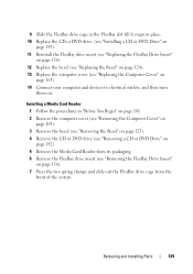
... the Bezel" on page 124). 13 Replace the computer cover (see "Removing the FlexBay Drive Insert" on . 9 Slide the FlexBay drive cage in the FlexBay slot till it snaps in "Before You Begin" on page 101. 2 Remove the computer cover (see "Removing the Computer Cover" on page 103). 3 Remove the bezel...
... the Bezel" on page 124). 13 Replace the computer cover (see "Removing the FlexBay Drive Insert" on . 9 Slide the FlexBay drive cage in the FlexBay slot till it snaps in "Before You Begin" on page 101. 2 Remove the computer cover (see "Removing the Computer Cover" on page 103). 3 Remove the bezel...
Owner's Manual
Page 140
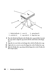
1 2 3 4 6 5 1 Media Card Reader 2 screws (2) 3 spring clamp (2) 4 notch hole (2) 5 cage notch (2) 6 floppy drive cage 8 Place the Media Card Reader in the FlexBay drive cage and slide it towards the cage notch to align the cage notch with the notch holes in the floppy drive. 9 Align the two screw holes on the floppy drive with the FlexBay drive cage. 10 Tighten the two screws to secure the floppy drive in the FlexBay drive cage. 11 Slide the FlexBay drive cage along with the floppy drive in the FlexBay slot till it snaps in place. 140 Removing and Installing Parts
1 2 3 4 6 5 1 Media Card Reader 2 screws (2) 3 spring clamp (2) 4 notch hole (2) 5 cage notch (2) 6 floppy drive cage 8 Place the Media Card Reader in the FlexBay drive cage and slide it towards the cage notch to align the cage notch with the notch holes in the floppy drive. 9 Align the two screw holes on the floppy drive with the FlexBay drive cage. 10 Tighten the two screws to secure the floppy drive in the FlexBay drive cage. 11 Slide the FlexBay drive cage along with the floppy drive in the FlexBay slot till it snaps in place. 140 Removing and Installing Parts
Owner's Manual
Page 143
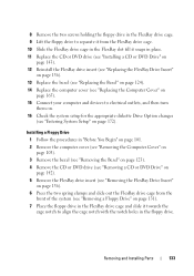
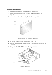
Installing a CD or DVD Drive 1 Follow the procedures in "Before You Begin" on page 101. 2 Remove the computer cover (see "Removing the Computer Cover" on page 103). 3 Remove the bezel (see "Removing the Bezel" on page 123). 1 2 1 shoulder screws (2) 2 CD or DVD drive 4 Fix the two shoulder screws on the CD or DVD drive. 5 Align the shoulder screw of the CD or DVD drive with the slots in the CD or DVD drive bay. 6 Gently slide the CD or DVD drive till it snaps in place. 1 1 CD or DVD drive Removing and Installing Parts 143
Installing a CD or DVD Drive 1 Follow the procedures in "Before You Begin" on page 101. 2 Remove the computer cover (see "Removing the Computer Cover" on page 103). 3 Remove the bezel (see "Removing the Bezel" on page 123). 1 2 1 shoulder screws (2) 2 CD or DVD drive 4 Fix the two shoulder screws on the CD or DVD drive. 5 Align the shoulder screw of the CD or DVD drive with the slots in the CD or DVD drive bay. 6 Gently slide the CD or DVD drive till it snaps in place. 1 1 CD or DVD drive Removing and Installing Parts 143
Owner's Manual
Page 153
... to the I/O panel from the system board. 5 Remove the screw that they have had sufficient time to release the I/O panel clamp from the I/O panel clamp slot. 7 Carefully remove the I/O panel from the computer. CAUTION: The heat sink assembly, power supply, and other unexpected injuries, always unplug your computer from your body...
... to the I/O panel from the system board. 5 Remove the screw that they have had sufficient time to release the I/O panel clamp from the I/O panel clamp slot. 7 Carefully remove the I/O panel from the computer. CAUTION: The heat sink assembly, power supply, and other unexpected injuries, always unplug your computer from your body...

Owner's Manual
Page 154
...Connect your computer and devices to an electrical outlet, and turn them on. 8 Verify that the computer works correctly by running the Dell Diagnostics (see "Dell Diagnostics" on page 84). 154 Removing and Installing Parts NOTICE: Take care not to damage the cable connectors and the cable routing ...clips when sliding the I/O panel into the computer. 2 Align and slide the I/O panel clamp in the I/O panel clamp slot. 3 Replace and tighten the screw ...
...Connect your computer and devices to an electrical outlet, and turn them on. 8 Verify that the computer works correctly by running the Dell Diagnostics (see "Dell Diagnostics" on page 84). 154 Removing and Installing Parts NOTICE: Take care not to damage the cable connectors and the cable routing ...clips when sliding the I/O panel into the computer. 2 Align and slide the I/O panel clamp in the I/O panel clamp slot. 3 Replace and tighten the screw ...

Owner's Manual
Page 155
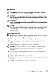
... have had sufficient time to components inside your computer, discharge static electricity from the electrical outlet before opening the cover. 1 2 3 1 I/O panel 2 I/O panel clamp 3 I/O panel clamp slot Processor Fan CAUTION: Before you begin any of the procedures in this section, follow the safety instructions in "Before You Begin" on page 101. 2 Remove...
... have had sufficient time to components inside your computer, discharge static electricity from the electrical outlet before opening the cover. 1 2 3 1 I/O panel 2 I/O panel clamp 3 I/O panel clamp slot Processor Fan CAUTION: Before you begin any of the procedures in this section, follow the safety instructions in "Before You Begin" on page 101. 2 Remove...

Owner's Manual
Page 164
... into the hinge tabs located along the edge of the computer. 2 Pivot the support bracket downward. 3 Align the notch in the support bracket with the slot in the hard drive bay and press it toward the back of the procedures in this section, follow the safety instructions located in cards on..." on page 165). 8 Connect your computer and devices to an electrical outlet, and turn them on. 9 Verify that the computer works correctly by running the Dell Diagnostics (see "Dell Diagnostics" on page 84).
... into the hinge tabs located along the edge of the computer. 2 Pivot the support bracket downward. 3 Align the notch in the support bracket with the slot in the hard drive bay and press it toward the back of the procedures in this section, follow the safety instructions located in cards on..." on page 165). 8 Connect your computer and devices to an electrical outlet, and turn them on. 9 Verify that the computer works correctly by running the Dell Diagnostics (see "Dell Diagnostics" on page 84).


