Specifications
Page 1
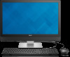
... jurisdictions. A00 Regulatory model: W12C | Type: W12C004 Computer model: Inspiron 24-5459 NOTE: The images in the United States and/or other marks and names mentioned herein may differ from your computer depending on the configuration you ordered. Inspiron 24 5000 Series Views Specifications Copyright © 2015 Dell Inc. This product is protected by U.S. and international copyright and intellectual property laws. Dell™ and the...
... jurisdictions. A00 Regulatory model: W12C | Type: W12C004 Computer model: Inspiron 24-5459 NOTE: The images in the United States and/or other marks and names mentioned herein may differ from your computer depending on the configuration you ordered. Inspiron 24 5000 Series Views Specifications Copyright © 2015 Dell Inc. This product is protected by U.S. and international copyright and intellectual property laws. Dell™ and the...
Specifications
Page 5
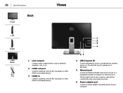
... lights next to the connector indicate the connectivity status and network activity. 6 Power-adapter port Connect a power adapter to provide power to 480 Mbps. 5 Network port Connect an Ethernet (RJ45) cable from a router or a broadband modem for network or internet access. Specifications Front Back Views Left Right Back Tilt 1 Line-out port Connect audio-output devices such as speakers, amplifiers, and so on. 2 HDMI-out port Connect a gaming console, Blu‑ray player, or other HDMI‑out enabled devices. 3 HDMI-in Connect...
... lights next to the connector indicate the connectivity status and network activity. 6 Power-adapter port Connect a power adapter to provide power to 480 Mbps. 5 Network port Connect an Ethernet (RJ45) cable from a router or a broadband modem for network or internet access. Specifications Front Back Views Left Right Back Tilt 1 Line-out port Connect audio-output devices such as speakers, amplifiers, and so on. 2 HDMI-out port Connect a gaming console, Blu‑ray player, or other HDMI‑out enabled devices. 3 HDMI-in Connect...

Specifications
Page 10
Views Ports and connectors External: Network USB Audio/Video Internal: M.2 Specifications One RJ45 port • Four USB 2.0 ports • Two USB 3.0 ports • One headset port • One line-out port • One HDMI-out port • One HDMI-in port One M.2 slot for WLAN and Bluetooth combo card Dimensions and weight System information Memory Ports and connectors Communications Video Audio Media-card reader Display Camera Stand Power adapter Computer environment Storage
Views Ports and connectors External: Network USB Audio/Video Internal: M.2 Specifications One RJ45 port • Four USB 2.0 ports • Two USB 3.0 ports • One headset port • One line-out port • One HDMI-out port • One HDMI-in port One M.2 slot for WLAN and Bluetooth combo card Dimensions and weight System information Memory Ports and connectors Communications Video Audio Media-card reader Display Camera Stand Power adapter Computer environment Storage

Specifications
Page 14
Views Storage Interface Hard drive Optical drive Specifications • SATA 3 Gbps for optical drive • SATA 6 Gbps for hard drive One 2.5-inch drive One 9.5-mm DVD+/-RW drive Dimensions and weight System information Memory Ports and connectors Communications Video Audio Media-card reader Display Camera Stand Power adapter Computer environment Storage
Views Storage Interface Hard drive Optical drive Specifications • SATA 3 Gbps for optical drive • SATA 6 Gbps for hard drive One 2.5-inch drive One 9.5-mm DVD+/-RW drive Dimensions and weight System information Memory Ports and connectors Communications Video Audio Media-card reader Display Camera Stand Power adapter Computer environment Storage

Specifications
Page 20
....04-1985 Operating Temperature range 0°C to 35°C (32°F to 95°F) Relative humidity (maximum) 10% to 90% (non-condensing) Vibration (maximum)* 0.66 GRMS Shock (maximum) 110 G† Altitude (maximum) -15.2 m to 3048 m (-50 ft to 35,000 ft) Dimensions and weight System information Memory Ports and connectors Communications Video Audio Media-card reader Display Camera Stand Power adapter Computer...
....04-1985 Operating Temperature range 0°C to 35°C (32°F to 95°F) Relative humidity (maximum) 10% to 90% (non-condensing) Vibration (maximum)* 0.66 GRMS Shock (maximum) 110 G† Altitude (maximum) -15.2 m to 3048 m (-50 ft to 35,000 ft) Dimensions and weight System information Memory Ports and connectors Communications Video Audio Media-card reader Display Camera Stand Power adapter Computer...
Service Manual
Page 4
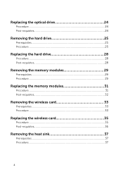
Replacing the optical drive 24 Procedure...24 Post-requisites 24 Removing the hard drive 25 Prerequisites...25 Procedure...25 Replacing the hard drive 28 Procedure...28 Post-requisites 28 Removing the memory modules 29 Prerequisites...29 Procedure...29 Replacing the memory modules 31 Procedure...31 Post-requisites 32 Removing the wireless card 33 Prerequisites...33 Procedure...33 Replacing the wireless card 35 Procedure...35 Post-requisites 36 Removing the heat sink 37 Prerequisites...37 Procedure...37 4
Replacing the optical drive 24 Procedure...24 Post-requisites 24 Removing the hard drive 25 Prerequisites...25 Procedure...25 Replacing the hard drive 28 Procedure...28 Post-requisites 28 Removing the memory modules 29 Prerequisites...29 Procedure...29 Replacing the memory modules 31 Procedure...31 Post-requisites 32 Removing the wireless card 33 Prerequisites...33 Procedure...33 Replacing the wireless card 35 Procedure...35 Post-requisites 36 Removing the heat sink 37 Prerequisites...37 Procedure...37 4

Service Manual
Page 9
... the power button for shut-down your computer. - NOTE: The images in this document may differ from your computer depending on the configuration you begin 1 Save and close all open files and exit all open applications. 2 Shut down instructions. 3 Disconnect your computer and all attached devices and peripherals, such as keyboard, mouse, monitor, and so on, from your computer. 6 Remove any media card and optical disc...
... the power button for shut-down your computer. - NOTE: The images in this document may differ from your computer depending on the configuration you begin 1 Save and close all open files and exit all open applications. 2 Shut down instructions. 3 Disconnect your computer and all attached devices and peripherals, such as keyboard, mouse, monitor, and so on, from your computer. 6 Remove any media card and optical disc...

Service Manual
Page 10
... anything inside the computer, replace all power sources before disconnecting the cable. CAUTION: Press and eject any connector pins. When connecting cables, ensure that is not authorized by Dell is flat and clean. Damage due to servicing that the ports and connectors are correctly oriented and aligned. After you must disengage before opening the computer cover or panels. CAUTION: You should only perform troubleshooting and repairs as...
... anything inside the computer, replace all power sources before disconnecting the cable. CAUTION: Press and eject any connector pins. When connecting cables, ensure that is not authorized by Dell is flat and clean. Damage due to servicing that the ports and connectors are correctly oriented and aligned. After you must disengage before opening the computer cover or panels. CAUTION: You should only perform troubleshooting and repairs as...

Service Manual
Page 12
After working inside your computer CAUTION: Leaving stray or loose screws inside your computer may severely damage your computer. 1 Replace all screws and ensure that no stray screws remain inside your computer. 2 Connect any external devices, peripherals, and cables you removed before working on your computer. 3 Replace any media cards, discs, and any other parts that you removed before working on your computer. 4 Connect your computer and all attached devices to their electrical outlets. 5 Turn on your computer. 12
After working inside your computer CAUTION: Leaving stray or loose screws inside your computer may severely damage your computer. 1 Replace all screws and ensure that no stray screws remain inside your computer. 2 Connect any external devices, peripherals, and cables you removed before working on your computer. 3 Replace any media cards, discs, and any other parts that you removed before working on your computer. 4 Connect your computer and all attached devices to their electrical outlets. 5 Turn on your computer. 12
Service Manual
Page 13
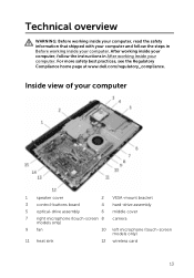
... in After working inside your computer. Technical overview WARNING: Before working inside your computer, read the safety information that shipped with your computer and follow the instructions in Before working inside your computer. Inside view of your computer 1 speaker cover 2 VESA-mount bracket 3 control-buttons board 4 hard-drive assembly 5 optical-drive assembly 6 middle cover 7 right microphone (touch-screen 8 camera models only) 9 fan 10 left microphone (touch-screen models only) 11 heat sink 12 wireless card 13...
... in After working inside your computer. Technical overview WARNING: Before working inside your computer, read the safety information that shipped with your computer and follow the instructions in Before working inside your computer. Inside view of your computer 1 speaker cover 2 VESA-mount bracket 3 control-buttons board 4 hard-drive assembly 5 optical-drive assembly 6 middle cover 7 right microphone (touch-screen 8 camera models only) 9 fan 10 left microphone (touch-screen models only) 11 heat sink 12 wireless card 13...
Service Manual
Page 14
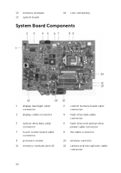
13 memory modules 15 system board 14 coin-cell battery System Board Components 1 display-backlight cable connector 3 display-cable connector 5 optical-drive data cable connector 7 touch-screen board cable connector 9 processor socket 11 memory-modules slots (2) 2 control-buttons board cable connector 4 hard-drive data cable connector 6 hard-drive and optical-drive power cable connector 8 fan cable connector 10 wireless-card slot 12 camera and microphone-cable connector 14
13 memory modules 15 system board 14 coin-cell battery System Board Components 1 display-backlight cable connector 3 display-cable connector 5 optical-drive data cable connector 7 touch-screen board cable connector 9 processor socket 11 memory-modules slots (2) 2 control-buttons board cable connector 4 hard-drive data cable connector 6 hard-drive and optical-drive power cable connector 8 fan cable connector 10 wireless-card slot 12 camera and microphone-cable connector 14

Service Manual
Page 28
... the hard-drive bracket with your computer and follow the instructions in Before working inside your computer. Replacing the hard drive WARNING: Before working inside your computer, read the safety information that secures the hard-drive assembly to the middle cover. 5 Connect the hard-drive cable to the hard drive. CAUTION: Hard drives are fragile. After working inside your computer, follow the steps in After working inside your computer. Exercise care when handling the hard drive. For...
... the hard-drive bracket with your computer and follow the instructions in Before working inside your computer. Replacing the hard drive WARNING: Before working inside your computer, read the safety information that secures the hard-drive assembly to the middle cover. 5 Connect the hard-drive cable to the hard drive. CAUTION: Hard drives are fragile. After working inside your computer, follow the steps in After working inside your computer. Exercise care when handling the hard drive. For...

Service Manual
Page 56
You must enter the Service Tag in After working inside your computer. You must make the desired changes again after you replace the system board. Prerequisites 1 Remove the stand. 2 Remove the back cover. 3 Remove the wireless card. 4 Remove the memory modules. 5 Remove the heat sink. 6 Remove the processor. 7 Remove the VESA-mount bracket. 56 For more safety best practices, see the Regulatory Compliance home page at www.dell.com/regulatory_compliance. NOTE: Before...
You must enter the Service Tag in After working inside your computer. You must make the desired changes again after you replace the system board. Prerequisites 1 Remove the stand. 2 Remove the back cover. 3 Remove the wireless card. 4 Remove the memory modules. 5 Remove the heat sink. 6 Remove the processor. 7 Remove the VESA-mount bracket. 56 For more safety best practices, see the Regulatory Compliance home page at www.dell.com/regulatory_compliance. NOTE: Before...

Service Manual
Page 58
3 Open the latches and disconnect the control-buttons board cable and display cable from the slots on the middle cover. 58 drive power cable 4 Remove the screws that secure the system board to the middle cover. 5 Starting from the inner edge, carefully lift the system board and release the ports from the system board. 1 display-backlight cable 3 display cable 5 optical-drive data cable 7 touch-screen board cable 2 control-buttons board cable 4 hard-drive data cable 6 hard-drive and optical-
3 Open the latches and disconnect the control-buttons board cable and display cable from the slots on the middle cover. 58 drive power cable 4 Remove the screws that secure the system board to the middle cover. 5 Starting from the inner edge, carefully lift the system board and release the ports from the system board. 1 display-backlight cable 3 display cable 5 optical-drive data cable 7 touch-screen board cable 2 control-buttons board cable 4 hard-drive data cable 6 hard-drive and optical-

Service Manual
Page 60
... the system board to the middle cover. 4 Connect the display-backlight cable to on the system board. 5 Slide the control-buttons board and display cables into their connectors on the system board and close the latches to secure the cables. 6 Connect the speaker, touch-screen board, hard-drive, optical-drive, hard-drive and optical-drive power, fan, and microphone and camera cables to the BIOS using the BIOS setup program. NOTE: Replacing the system board removes any changes you have made to the system board. After working inside your computer...
... the system board to the middle cover. 4 Connect the display-backlight cable to on the system board. 5 Slide the control-buttons board and display cables into their connectors on the system board and close the latches to secure the cables. 6 Connect the speaker, touch-screen board, hard-drive, optical-drive, hard-drive and optical-drive power, fan, and microphone and camera cables to the BIOS using the BIOS setup program. NOTE: Replacing the system board removes any changes you have made to the system board. After working inside your computer...

Service Manual
Page 70
... follow the instructions in Before working inside your computer. Post-requisites 1 Replace the speaker cover. 2 Replace the back cover. 3 Replace the stand. 70 For more safety best practices, see the Regulatory Compliance home page at www.dell.com/regulatory_compliance. Procedure 1 Using the alignment posts, place the speakers on the display assembly. 2 Route the speaker cable through the routing guide on the display bezel. 3 Route the speaker cable through the...
... follow the instructions in Before working inside your computer. Post-requisites 1 Replace the speaker cover. 2 Replace the back cover. 3 Replace the stand. 70 For more safety best practices, see the Regulatory Compliance home page at www.dell.com/regulatory_compliance. Procedure 1 Using the alignment posts, place the speakers on the display assembly. 2 Route the speaker cable through the routing guide on the display bezel. 3 Route the speaker cable through the...

Service Manual
Page 74
... After working inside your computer. Prerequisites 1 Remove the stand. 2 Remove the back cover. 3 Remove the optical drive. 4 Remove the hard drive. 5 Remove the wireless card. 6 Remove the heat sink. 7 Remove the fan. 8 Remove the system board. 9 Remove the VESA-mount bracket. 10 Remove the speaker cover. Procedure 1 Note the routing of the antenna, camera and microphone, touch-screen board, optical drive and hard drive cables and remove the cables from the routing guides on the middle cover. 2 Disconnect the touch-screen board and display-backlight cables from the display panel...
... After working inside your computer. Prerequisites 1 Remove the stand. 2 Remove the back cover. 3 Remove the optical drive. 4 Remove the hard drive. 5 Remove the wireless card. 6 Remove the heat sink. 7 Remove the fan. 8 Remove the system board. 9 Remove the VESA-mount bracket. 10 Remove the speaker cover. Procedure 1 Note the routing of the antenna, camera and microphone, touch-screen board, optical drive and hard drive cables and remove the cables from the routing guides on the middle cover. 2 Disconnect the touch-screen board and display-backlight cables from the display panel...

Service Manual
Page 79
... at www.dell.com/regulatory_compliance. After working inside your computer, follow the steps in After working inside your computer. Post-requisites 1 Replace the speaker cover. 2 Replace the VESA-mount bracket. 3 Replace the system board. 4 Replace the fan. 5 Replace the heat sink. 6 Replace the wireless card. 7 Replace the hard drive. 8 Replace the optical drive. 9 Replace the back cover. 79 Replacing the middle cover WARNING: Before working inside your computer, read the safety information that secure the middle cover to the display panel. Procedure...
... at www.dell.com/regulatory_compliance. After working inside your computer, follow the steps in After working inside your computer. Post-requisites 1 Replace the speaker cover. 2 Replace the VESA-mount bracket. 3 Replace the system board. 4 Replace the fan. 5 Replace the heat sink. 6 Replace the wireless card. 7 Replace the hard drive. 8 Replace the optical drive. 9 Replace the back cover. 79 Replacing the middle cover WARNING: Before working inside your computer, read the safety information that secure the middle cover to the display panel. Procedure...
Quick Start Guide - Windows 8
Page 1
... the keyboard and mouse. Inspiron 24 5000 Series Quick Start Guide Snelstartgids Guide d'information rapide Guía de inicio rápido 1 Set up the stand Stel de standaard in | Installez le socle Montaje del soporte Articulating stand Standaard met scharnier | Socle articulé Articulación del soporte Pedestal stand Voetstuk | Socle piédestal Soporte en pedestal 3 Connect the power adapter Sluit...
... the keyboard and mouse. Inspiron 24 5000 Series Quick Start Guide Snelstartgids Guide d'information rapide Guía de inicio rápido 1 Set up the stand Stel de standaard in | Installez le socle Montaje del soporte Articulating stand Standaard met scharnier | Socle articulé Articulación del soporte Pedestal stand Voetstuk | Socle piédestal Soporte en pedestal 3 Connect the power adapter Sluit...
Quick Start Guide - Windows 10
Page 1
... et sécurité Normativa y seguridad Regulatory model Wettelijk model | Modèle réglementaire Modelo normativo Regulatory type Wettelijk type | Type réglementaire Tipo normativo Computer model Computermodel | Modèle de l'ordinateur Modelo de equipo Dell.com/support Dell.com/support/manuals Dell.com/support/windows Dell.com/support/linux Dell.com/contactdell Dell.com/regulatory_compliance W12C W12C004 Inspiron 24-5459 © 2015 Dell Inc. © 2015 Microsoft Corporation. ©...
... et sécurité Normativa y seguridad Regulatory model Wettelijk model | Modèle réglementaire Modelo normativo Regulatory type Wettelijk type | Type réglementaire Tipo normativo Computer model Computermodel | Modèle de l'ordinateur Modelo de equipo Dell.com/support Dell.com/support/manuals Dell.com/support/windows Dell.com/support/linux Dell.com/contactdell Dell.com/regulatory_compliance W12C W12C004 Inspiron 24-5459 © 2015 Dell Inc. © 2015 Microsoft Corporation. ©...


