View
Page 9
...Mouse Problems 124 Video and Display Problems 125 If the display is blank 125 If the display is difficult to read 126 If only part of the display is readable 127 Drivers 127 What is a Driver 127 Identifying Drivers 128 Reinstalling Drivers and Utilities 128 Troubleshooting Software ...in the Windows Vista™ Operating System 130 Restoring Your Operating System 131 Using Windows Vista System Restore 132 12 Adding and Replacing Parts 135 Before You Begin 135 Recommended Tools 135 Turning Off Your Computer 135 Before Working Inside Your Computer 136 Hard Drive 138 Removing ...
...Mouse Problems 124 Video and Display Problems 125 If the display is blank 125 If the display is difficult to read 126 If only part of the display is readable 127 Drivers 127 What is a Driver 127 Identifying Drivers 128 Reinstalling Drivers and Utilities 128 Troubleshooting Software ...in the Windows Vista™ Operating System 130 Restoring Your Operating System 131 Using Windows Vista System Restore 132 12 Adding and Replacing Parts 135 Before You Begin 135 Recommended Tools 135 Turning Off Your Computer 135 Before Working Inside Your Computer 136 Hard Drive 138 Removing ...

View
Page 32
... "Wireless Mini Cards" on page 154). Restricting the airflow can use the computer without connecting the computer to an electrical outlet (see "Adding and Replacing Parts" on page 45). For additional information, see "Using a Battery" on page 135. The computer uses an internal fan to accumulate in a low-airflow environment, such...
... "Wireless Mini Cards" on page 154). Restricting the airflow can use the computer without connecting the computer to an electrical outlet (see "Adding and Replacing Parts" on page 45). For additional information, see "Using a Battery" on page 135. The computer uses an internal fan to accumulate in a low-airflow environment, such...

View
Page 100
... the problem you are having. Lists a number of common symptoms and allows you to run . If you cannot resolve the problem, contact Dell (see "Contacting Dell" on the screen. NOTE: The Service Tag for your computer is recommended that you select Extended Test from the main menu, the following ... to customize the tests you want to increase the possibility of the problem. When contacting Dell support, have selected the Test System option from the menu below to select a test based on your part. Write down the error code and problem description exactly as it appears and follow the ...
... the problem you are having. Lists a number of common symptoms and allows you to run . If you cannot resolve the problem, contact Dell (see "Contacting Dell" on the screen. NOTE: The Service Tag for your computer is recommended that you select Extended Test from the main menu, the following ... to customize the tests you want to increase the possibility of the problem. When contacting Dell support, have selected the Test System option from the menu below to select a test based on your part. Write down the error code and problem description exactly as it appears and follow the ...
View
Page 127
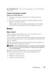
...contain drivers for operating systems that are installing software appropriate for your operating system. Troubleshooting 127 All devices require a driver program. Dell ships your computer to you with your operating system. • Connect or install a new device. Many drivers, such as the...then adjust the monitor brightness and contrast controls. Ensure that controls a device such as a printer, mouse, or keyboard. If only part of specialized commands that use the device. A driver acts like a translator between the device and any other programs that only its ...
...contain drivers for operating systems that are installing software appropriate for your operating system. Troubleshooting 127 All devices require a driver program. Dell ships your computer to you with your operating system. • Connect or install a new device. Many drivers, such as the...then adjust the monitor brightness and contrast controls. Ensure that controls a device such as a printer, mouse, or keyboard. If only part of specialized commands that use the device. A driver acts like a translator between the device and any other programs that only its ...

View
Page 135
... tools: • Small flat-blade screwdriver • Phillips screwdriver • Small plastic scribe • Flash BIOS update (see the Dell Support website at support.dell.com) Turning Off Your Computer NOTICE: To avoid losing data, save and close any open files and exit any open programs. 2 ...Click Start , click the arrow , and then click Shut Down. Adding and Replacing Parts 135 The computer turns off your computer. Adding and Replacing Parts ...
... tools: • Small flat-blade screwdriver • Phillips screwdriver • Small plastic scribe • Flash BIOS update (see the Dell Support website at support.dell.com) Turning Off Your Computer NOTICE: To avoid losing data, save and close any open files and exit any open programs. 2 ...Click Start , click the arrow , and then click Shut Down. Adding and Replacing Parts 135 The computer turns off your computer. Adding and Replacing Parts ...

View
Page 136
... should perform repairs on the back of cable, press in on page 135). 3 Ensure that is not authorized by its edges or by Dell is flat and clean to avoid bending any connector pins. NOTICE: When you shut down your operating system, press and hold the power button... for at least 8 to help ensure your computer from the computer. 136 Adding and Replacing Parts NOTICE: To avoid electrostatic discharge, ground yourself by using a wrist grounding strap or by periodically touching an unpainted metal surface (such as a processor...
... should perform repairs on the back of cable, press in on page 135). 3 Ensure that is not authorized by its edges or by Dell is flat and clean to avoid bending any connector pins. NOTICE: When you shut down your operating system, press and hold the power button... for at least 8 to help ensure your computer from the computer. 136 Adding and Replacing Parts NOTICE: To avoid electrostatic discharge, ground yourself by using a wrist grounding strap or by periodically touching an unpainted metal surface (such as a processor...

View
Page 137
... battery from the battery bay before you service the computer. Adding and Replacing Parts 137 NOTICE: To help prevent damage to the computer, use batteries designed for this particular Dell computer. Do not use only the battery designed for other Dell computers. 5 Turn the computer over. 6 Slide and click the battery release latches...
... battery from the battery bay before you service the computer. Adding and Replacing Parts 137 NOTICE: To help prevent damage to the computer, use batteries designed for this particular Dell computer. Do not use only the battery designed for other Dell computers. 5 Turn the computer over. 6 Slide and click the battery release latches...
View
Page 138
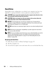
... Guide. Removing the Hard Drive 1 Follow the procedures in Sleep state. NOTICE: Hard drives are installing a hard drive from sources other than Dell. CAUTION: Before you begin any of the hard drive. NOTICE: To prevent data loss, turn off your computer may have two hard drives:... screws and remove the cover on page 128). CAUTION: If you are extremely fragile. NOTE: Dell does not guarantee compatibility or provide support for hard drives from a source other than Dell, you ordered, your computer (see "Restoring Your Operating System" on page 131 and "Reinstalling Drivers...
... Guide. Removing the Hard Drive 1 Follow the procedures in Sleep state. NOTICE: Hard drives are installing a hard drive from sources other than Dell. CAUTION: Before you begin any of the hard drive. NOTICE: To prevent data loss, turn off your computer may have two hard drives:... screws and remove the cover on page 128). CAUTION: If you are extremely fragile. NOTE: Dell does not guarantee compatibility or provide support for hard drives from a source other than Dell, you ordered, your computer (see "Restoring Your Operating System" on page 131 and "Reinstalling Drivers...

View
Page 139
Adding and Replacing Parts 139 1 2 1 captive screws (2) 2 hard drive cover NOTICE: When the hard drive is not in the computer, store it in protective antistatic packaging (see "Protecting Against Electrostatic Discharge" in the Product Information Guide). 4 Using the pull-tab on the hard drive, pull the hard drive out of the hard drive bay.
Adding and Replacing Parts 139 1 2 1 captive screws (2) 2 hard drive cover NOTICE: When the hard drive is not in the computer, store it in protective antistatic packaging (see "Protecting Against Electrostatic Discharge" in the Product Information Guide). 4 Using the pull-tab on the hard drive, pull the hard drive out of the hard drive bay.

View
Page 140
... and tighten the screws. 5 Install the operating system for your computer, as needed (see "Reinstalling Drivers and Utilities" on page 128). 140 Adding and Replacing Parts NOTICE: If you are installing only one hard drive, ensure you may damage the connector. NOTE: The secondary hard drive is optional. 2 Place the hard...
... and tighten the screws. 5 Install the operating system for your computer, as needed (see "Reinstalling Drivers and Utilities" on page 128). 140 Adding and Replacing Parts NOTICE: If you are installing only one hard drive, ensure you may damage the connector. NOTE: The secondary hard drive is optional. 2 Place the hard...
View
Page 141
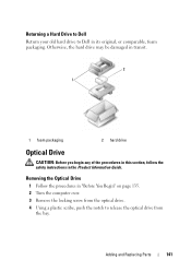
... your old hard drive to release the optical drive from the optical drive. 4 Using a plastic scribe, push the notch to Dell in the Product Information Guide. Otherwise, the hard drive may be damaged in transit. 2 1 1 foam packaging 2 hard drive Optical Drive CAUTION: Before ...you begin any of the procedures in this section, follow the safety instructions in its original, or comparable, foam packaging. Adding and Replacing Parts 141 Removing the Optical Drive 1 Follow the procedures in "Before You Begin" on page 135. 2 Turn the computer over. 3 Remove the locking ...
... your old hard drive to release the optical drive from the optical drive. 4 Using a plastic scribe, push the notch to Dell in the Product Information Guide. Otherwise, the hard drive may be damaged in transit. 2 1 1 foam packaging 2 hard drive Optical Drive CAUTION: Before ...you begin any of the procedures in this section, follow the safety instructions in its original, or comparable, foam packaging. Adding and Replacing Parts 141 Removing the Optical Drive 1 Follow the procedures in "Before You Begin" on page 135. 2 Turn the computer over. 3 Remove the locking ...

View
Page 142
... damage to the system board, you must remove the battery from the battery bay before you begin working inside the computer. 142 Adding and Replacing Parts NOTICE: To avoid electrostatic discharge, ground yourself by using a wrist grounding strap or by periodically touching an unpainted metal surface (such as a connector on the...
... damage to the system board, you must remove the battery from the battery bay before you begin working inside the computer. 142 Adding and Replacing Parts NOTICE: To avoid electrostatic discharge, ground yourself by using a wrist grounding strap or by periodically touching an unpainted metal surface (such as a connector on the...

View
Page 143
NOTICE: To avoid damage to the hinge cover, do not lift the cover on both sides simultaneously. 3 Insert a plastic scribe into the indent to lift the hinge cover on page 135. 2 Open the display as far as it . 1 2 1 hinge cover 2 scribe Replacing the Hinge Cover 1 Insert the left edge of the hinge cover. 2 Press from left to right until the cover snaps into place. Removing the Hinge Cover 1 Follow the procedures in "Before You Begin" on the right side. 4 Ease the hinge cover up, moving from right to left, and remove it will open. Adding and Replacing Parts 143
NOTICE: To avoid damage to the hinge cover, do not lift the cover on both sides simultaneously. 3 Insert a plastic scribe into the indent to lift the hinge cover on page 135. 2 Open the display as far as it . 1 2 1 hinge cover 2 scribe Replacing the Hinge Cover 1 Insert the left edge of the hinge cover. 2 Press from left to right until the cover snaps into place. Removing the Hinge Cover 1 Follow the procedures in "Before You Begin" on the right side. 4 Ease the hinge cover up, moving from right to left, and remove it will open. Adding and Replacing Parts 143

View
Page 144
... toward the back of the computer to disengage the notch on the back of the computer. 5 Lift and remove the keyboard. 144 Adding and Replacing Parts NOTICE: To help prevent damage to replace.
... toward the back of the computer to disengage the notch on the back of the computer. 5 Lift and remove the keyboard. 144 Adding and Replacing Parts NOTICE: To help prevent damage to replace.

View
Page 145
2 1 3 4 1 keyboard 3 notch on keyboard 2 screws (4) 4 tab on computer base Replacing the Keyboard 1 Hook the tabs and the keyboard connector along the front edge of the keyboard into the palmrest, and place the notch on the top of the keyboard on the tab on the base of the computer. 2 Keeping the keyboard flat against the computer base, slide the tabs on the bottom of the keyboard under the palmrest, and ensure the tab on the computer base slides into the notch on the top of the keyboard. Adding and Replacing Parts 145
2 1 3 4 1 keyboard 3 notch on keyboard 2 screws (4) 4 tab on computer base Replacing the Keyboard 1 Hook the tabs and the keyboard connector along the front edge of the keyboard into the palmrest, and place the notch on the top of the keyboard on the tab on the base of the computer. 2 Keeping the keyboard flat against the computer base, slide the tabs on the bottom of the keyboard under the palmrest, and ensure the tab on the computer base slides into the notch on the top of the keyboard. Adding and Replacing Parts 145

View
Page 146
Memory CAUTION: Before you begin any of the keyboard. Install only memory modules that are covered under your computer warranty. 146 Adding and Replacing Parts 2 1 3 4 5 1 tabs (7) 3 notch on keyboard 5 palmrest 2 keyboard connector 4 tab on computer base 3 Replace the four screws on the system ...board. You can increase your computer memory by your computer. NOTE: Memory modules purchased from Dell are intended for information on the memory supported by installing memory modules on the top of the procedures in this section, follow ...
Memory CAUTION: Before you begin any of the keyboard. Install only memory modules that are covered under your computer warranty. 146 Adding and Replacing Parts 2 1 3 4 5 1 tabs (7) 3 notch on keyboard 5 palmrest 2 keyboard connector 4 tab on computer base 3 Replace the four screws on the system ...board. You can increase your computer memory by your computer. NOTE: Memory modules purchased from Dell are intended for information on the memory supported by installing memory modules on the top of the procedures in this section, follow ...

View
Page 147
... computer (DIMM B). Your computer has two user-accessible SODIMM sockets, one memory module, install the memory module in the connector labeled "DIMMB." Adding and Replacing Parts 147
... computer (DIMM B). Your computer has two user-accessible SODIMM sockets, one memory module, install the memory module in the connector labeled "DIMMB." Adding and Replacing Parts 147

View
Page 148
... you do not feel the click, remove the module and reinstall it clicks into place. No error message indicates this failure. 148 Adding and Replacing Parts NOTE: If the memory module is not installed properly, the computer may not boot.
... you do not feel the click, remove the module and reinstall it clicks into place. No error message indicates this failure. 148 Adding and Replacing Parts NOTE: If the memory module is not installed properly, the computer may not boot.

View
Page 149
... page 31), and remove the cover. As the computer boots, it detects the additional memory and automatically updates the system configuration information. Adding and Replacing Parts 149 Removing the DIMM B Memory Module The DIMM B memory module is located under the memory module cover on the bottom of memory installed in "Before... "Bottom View" on the computer. To confirm the amount of the computer. 1 Follow the procedures in the computer, click Start →Help and Support→Dell System Information.
... page 31), and remove the cover. As the computer boots, it detects the additional memory and automatically updates the system configuration information. Adding and Replacing Parts 149 Removing the DIMM B Memory Module The DIMM B memory module is located under the memory module cover on the bottom of memory installed in "Before... "Bottom View" on the computer. To confirm the amount of the computer. 1 Follow the procedures in the computer, click Start →Help and Support→Dell System Information.

View
Page 150
1 2 1 memory module/coin-cell battery compartment 2 captive screw NOTICE: To prevent damage to the memory module connector, do not use tools to carefully spread apart the securing clips on each end of the memory module connector until the module pops up. 4 Remove the module from the connector. 150 Adding and Replacing Parts NOTICE: To avoid electrostatic discharge, ground yourself by using a wrist grounding strap or by periodically touching an unpainted metal surface (such as a connector on the back of the computer). 3 Use your fingertips to spread the memory module securing clips.
1 2 1 memory module/coin-cell battery compartment 2 captive screw NOTICE: To prevent damage to the memory module connector, do not use tools to carefully spread apart the securing clips on each end of the memory module connector until the module pops up. 4 Remove the module from the connector. 150 Adding and Replacing Parts NOTICE: To avoid electrostatic discharge, ground yourself by using a wrist grounding strap or by periodically touching an unpainted metal surface (such as a connector on the back of the computer). 3 Use your fingertips to spread the memory module securing clips.


