
Owner's Manual
Page 10
... Drive 137 Returning a Hard Drive to Dell 137 Optical Drive 138 Removing the Optical Drive 138 Replacing the Optical Drive 138 Hinge Cover 139 Removing the Hinge Cover 139 Replacing the Hinge Cover 140 Keyboard 140 Removing the Keyboard 141 Replacing the Keyboard 142 Memory 142 Removing Memory Module 142 Replacing Memory Module 144 Subscriber Identity Module (Optional...
... Drive 137 Returning a Hard Drive to Dell 137 Optical Drive 138 Removing the Optical Drive 138 Replacing the Optical Drive 138 Hinge Cover 139 Removing the Hinge Cover 139 Replacing the Hinge Cover 140 Keyboard 140 Removing the Keyboard 141 Replacing the Keyboard 142 Memory 142 Removing Memory Module 142 Replacing Memory Module 144 Subscriber Identity Module (Optional...
Owner's Manual
Page 110
.... The system configuration information does not match the hardware configuration. Restart the computer, and avoid touching the keyboard or the mouse during the boot routine. K E Y B O A R D D A T A L I N E F A I R E C T - L I C E N S E D C O N T E N T I S N O T A C C E S S I B L E I N M E D I A D I L U R E - Reinstall the memory modules and, if necessary, replace them (see "Dell MediaDirect problems" on page 95). If the error message still appears, see "Using the System Setup Program...
.... The system configuration information does not match the hardware configuration. Restart the computer, and avoid touching the keyboard or the mouse during the boot routine. K E Y B O A R D D A T A L I N E F A I R E C T - L I C E N S E D C O N T E N T I S N O T A C C E S S I B L E I N M E D I A D I L U R E - Reinstall the memory modules and, if necessary, replace them (see "Dell MediaDirect problems" on page 95). If the error message still appears, see "Using the System Setup Program...

Owner's Manual
Page 112
... U N E X P E C T E D I N T E R R U P T I B L E . The keyboard controller may be malfunctioning, or a memory module may be malfunctioning. X : \ I S N O T A C C E S S I N P R O T E C T E D M O D E - Replace the battery, or connect the computer to charge the battery. TI M E- System configuration settings are defective, back up the data... system configuration settings may have a defective sector or corrupted FAT on page 160). See Windows Help and Support for the Date and Time options (see "Dell Diagnostics" on page 171). WA R N I N G : B A T T E R Y I S C R I T I C A L...
... U N E X P E C T E D I N T E R R U P T I B L E . The keyboard controller may be malfunctioning, or a memory module may be malfunctioning. X : \ I S N O T A C C E S S I N P R O T E C T E D M O D E - Replace the battery, or connect the computer to charge the battery. TI M E- System configuration settings are defective, back up the data... system configuration settings may have a defective sector or corrupted FAT on page 160). See Windows Help and Support for the Date and Time options (see "Dell Diagnostics" on page 171). WA R N I N G : B A T T E R Y I S C R I T I C A L...
Owner's Manual
Page 142
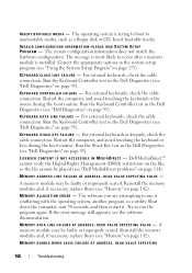
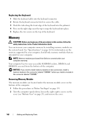
... touching an unpainted metal surface (such as a connector on page 39. Keyboard For more information about the keyboard, see "Using the Keyboard and Touchpad" on the back of the hinge cover. 3 Press from left to right until the cover snaps into place. 4 Replace the two screws that secure the hinge cover from the battery...
... touching an unpainted metal surface (such as a connector on page 39. Keyboard For more information about the keyboard, see "Using the Keyboard and Touchpad" on the back of the hinge cover. 3 Press from left to right until the cover snaps into place. 4 Replace the two screws that secure the hinge cover from the battery...
Owner's Manual
Page 143
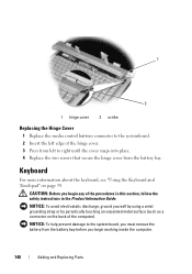
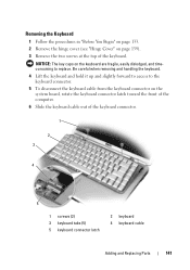
... 139). 3 Remove the two screws at the top of the keyboard connector. 1 2 3 4 5 1 screws (2) 3 keyboard tabs (5) 5 keyboard connector latch 2 keyboard 4 keyboard cable Adding and Replacing Parts 141 Be careful when removing and handling the keyboard. 4 Lift the keyboard and hold it up and slightly forward to access to replace. Removing the Keyboard 1 Follow the procedures in "Before You Begin" on page...
... 139). 3 Remove the two screws at the top of the keyboard connector. 1 2 3 4 5 1 screws (2) 3 keyboard tabs (5) 5 keyboard connector latch 2 keyboard 4 keyboard cable Adding and Replacing Parts 141 Be careful when removing and handling the keyboard. 4 Lift the keyboard and hold it up and slightly forward to access to replace. Removing the Keyboard 1 Follow the procedures in "Before You Begin" on page...
Owner's Manual
Page 144
... modules that are covered under the memory module cover on page 29), and remove the cover. 142 Adding and Replacing Parts NOTICE: If you need to snap the keyboard into the palmrest. 4 Press on the right edge near the top to install memory modules in two connectors,... the safety instructions in the connector labeled "DIMMB." Your computer has two user-accessible SODIMM sockets, DIMM A and DIMM B, accessed from Dell are intended for information on the system board. Memory CAUTION: Before you install a module in the Product Information Guide. Removing Memory Module The...
... modules that are covered under the memory module cover on page 29), and remove the cover. 142 Adding and Replacing Parts NOTICE: If you need to snap the keyboard into the palmrest. 4 Press on the right edge near the top to install memory modules in two connectors,... the safety instructions in the connector labeled "DIMMB." Your computer has two user-accessible SODIMM sockets, DIMM A and DIMM B, accessed from Dell are intended for information on the system board. Memory CAUTION: Before you install a module in the Product Information Guide. Removing Memory Module The...

Owner's Manual
Page 201
... installing, 78 removing, 79 F FCM. See Flash Cache Module Flash Cache Module, 149 H hard drive problems, 104 replacing, 135 returning to Dell, 137 hardware Dell Diagnostics, 95 Hardware Troubleshooter, 127 hinge cover removing, 139 I IEEE 1394 connector description, 26 problems, 111 Internet connection... setting up, 32 K keyboard numeric keypad, 39 problems, 112 removing, 140 shortcuts, 40 keyboard status lights description, 23 keypad numeric, 39 L labels Microsoft Windows, 14 Service Tag, 14 lost computer, 94 M media playing, 51 media control buttons Dell MediaDirect button, 58 description,...
... installing, 78 removing, 79 F FCM. See Flash Cache Module Flash Cache Module, 149 H hard drive problems, 104 replacing, 135 returning to Dell, 137 hardware Dell Diagnostics, 95 Hardware Troubleshooter, 127 hinge cover removing, 139 I IEEE 1394 connector description, 26 problems, 111 Internet connection... setting up, 32 K keyboard numeric keypad, 39 problems, 112 removing, 140 shortcuts, 40 keyboard status lights description, 23 keypad numeric, 39 L labels Microsoft Windows, 14 Service Tag, 14 lost computer, 94 M media playing, 51 media control buttons Dell MediaDirect button, 58 description,...

Service Manual
Page 7
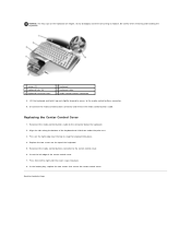
...procedures in this section, follow the safety instructions in the Product Information Guide. Remove the keyboard (see Replacing the Center Control Cover). Replace the center control cover (see Removing the Keyboard). 4. Follow the procedures in position and gently press until the button board secures within.... Connect the button board cable to Contents Page Back to Contents Page Button Board Dell™ Inspiron™ 1525/1526 Service Manual CAUTION: Before you begin any of the computer). Replace the keyboard (see Replacing the Keyboard). 5. Back to the system board. 3.
...procedures in this section, follow the safety instructions in the Product Information Guide. Remove the keyboard (see Replacing the Center Control Cover). Replace the center control cover (see Removing the Keyboard). 4. Follow the procedures in position and gently press until the button board secures within.... Connect the button board cable to Contents Page Back to Contents Page Button Board Dell™ Inspiron™ 1525/1526 Service Manual CAUTION: Before you begin any of the computer). Replace the keyboard (see Replacing the Keyboard). 5. Back to the system board. 3.
Service Manual
Page 10
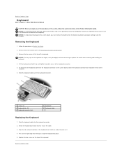
... fragile, easily dislodged, and time-consuming to the connector below the keyboard. 2. Reconnect the media control buttons cable to replace. Align the tabs along the bottom of the keyboard. 5. Be careful when removing and handling the keyboard. 1 screws (2) 3 keyboard tabs (5) 5 keyboard connector latch 2 keyboard 4 keyboard cable 6 media control buttons connector 8. Back to the center control cover. 6. Reconnect the...
... fragile, easily dislodged, and time-consuming to the connector below the keyboard. 2. Reconnect the media control buttons cable to replace. Align the tabs along the bottom of the keyboard. 5. Be careful when removing and handling the keyboard. 1 screws (2) 3 keyboard tabs (5) 5 keyboard connector latch 2 keyboard 4 keyboard cable 6 media control buttons connector 8. Back to the center control cover. 6. Reconnect the...

Service Manual
Page 11
Remove the hard drive (see Removing the Keyboard). 8. Remove the keyboard (see Removing the Hard Drive). 4. Remove the processor thermal-cooling assembly (see Removing the Display Assembly). 9. Use a plastic scribe to Contents Page Coin-Cell Battery Dell™ Inspiron™ 1525/1526 Service Manual Removing the Coin-Cell Battery Replacing the Coin-Cell Battery Removing the Coin...
Remove the hard drive (see Removing the Keyboard). 8. Remove the keyboard (see Removing the Hard Drive). 4. Remove the processor thermal-cooling assembly (see Removing the Display Assembly). 9. Use a plastic scribe to Contents Page Coin-Cell Battery Dell™ Inspiron™ 1525/1526 Service Manual Removing the Coin-Cell Battery Replacing the Coin-Cell Battery Removing the Coin...

Service Manual
Page 19
... from around the display bezel. 6. Replace the keyboard (see Wireless Mini- Connect the antennae cables to the Mini-Cards (see Replacing the Keyboard). 9. Cards). 13. Remove the captive screw and five shoulder screws from the bottom corner of the computer. 12. Replace the center control cover (see Removing ... the display cable to the camera cable connector on the system board. 7. Replace the back cover and tighten the eight captive screws on the cover. Remove the display assembly (see Removing the Keyboard). 4. NOTE: Ensure that the display cable, camera cable, and antenna cables...
... from around the display bezel. 6. Replace the keyboard (see Wireless Mini- Connect the antennae cables to the Mini-Cards (see Replacing the Keyboard). 9. Cards). 13. Remove the captive screw and five shoulder screws from the bottom corner of the computer. 12. Replace the center control cover (see Removing ... the display cable to the camera cable connector on the system board. 7. Replace the back cover and tighten the eight captive screws on the cover. Remove the display assembly (see Removing the Keyboard). 4. NOTE: Ensure that the display cable, camera cable, and antenna cables...

Service Manual
Page 20
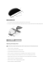
...to the display panel and remove the brackets. Remove the display assembly (see Removing the Keyboard). 4. Remove the display bezel (see Replacing the Center Control Cover). Display Panel Removing the Display Panel CAUTION: Before you begin the ...2 display panel 7. Replace the captive screw and five shoulder screws around the display bezel. 5. Replace the center control cover (see Removing the Display Bezel). 6. Replace the six rubber display bumpers around the display bezel. 4. Replace the keyboard (see Replacing the Keyboard). 7. Replacing the Display Bezel CAUTION...
...to the display panel and remove the brackets. Remove the display assembly (see Removing the Keyboard). 4. Remove the display bezel (see Replacing the Center Control Cover). Display Panel Removing the Display Panel CAUTION: Before you begin the ...2 display panel 7. Replace the captive screw and five shoulder screws around the display bezel. 5. Replace the center control cover (see Removing the Display Bezel). 6. Replace the six rubber display bumpers around the display bezel. 4. Replace the keyboard (see Replacing the Keyboard). 7. Replacing the Display Bezel CAUTION...
Service Manual
Page 21
... 4. Connect the bottom flex-cable connector to disconnect the top flex-cable connector from the invertor connector. 10. Replace the display assembly (see Replacing the Keyboard). Follow the instructions in the Product Information Guide. 1. Align the screw holes on the display panel with the corresponding... screw holes and guide pins on each side of the display panel) to secure the display brackets to the cover. 6. Replace the keyboard (see Replacing the Display Assembly). 9. Use the pull tab to the display connector. 3. Connect the top flex-cable connector to disconnect ...
... 4. Connect the bottom flex-cable connector to disconnect the top flex-cable connector from the invertor connector. 10. Replace the display assembly (see Replacing the Keyboard). Follow the instructions in the Product Information Guide. 1. Align the screw holes on the display panel with the corresponding... screw holes and guide pins on each side of the display panel) to secure the display brackets to the cover. 6. Replace the keyboard (see Replacing the Display Assembly). 9. Use the pull tab to the display connector. 3. Connect the top flex-cable connector to disconnect ...

Service Manual
Page 22
... the Display Panel). 7. Disconnect the camera cable connector from the camera and microphone asssembly. 8. Remove the display assembly (see Removing the Keyboard). 4. Remove the keyboard (see Removing the Display Assembly). 5. Replace the center control cover (see Removing the Center Control Cover). 3. Lift the camera and microphone assembly out of the display cover. 1 camera...
... the Display Panel). 7. Disconnect the camera cable connector from the camera and microphone asssembly. 8. Remove the display assembly (see Removing the Keyboard). 4. Remove the keyboard (see Removing the Display Assembly). 5. Replace the center control cover (see Removing the Center Control Cover). 3. Lift the camera and microphone assembly out of the display cover. 1 camera...
Service Manual
Page 23
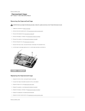
... palm rest (see Removing the Center Control Cover). 3. Remove the center control cover (see Replacing the Palm Rest). 4. Back to Contents Page Replace the display assembly (see Replacing the Keyboard). 7. Back to Contents Page ExpressCard Cage Dell™ Inspiron™ 1525/1526 Service Manual Removing the ExpressCard Cage CAUTION: Before you begin the following procedure, follow the...
... palm rest (see Removing the Center Control Cover). 3. Remove the center control cover (see Replacing the Palm Rest). 4. Back to Contents Page Replace the display assembly (see Replacing the Keyboard). 7. Back to Contents Page ExpressCard Cage Dell™ Inspiron™ 1525/1526 Service Manual Removing the ExpressCard Cage CAUTION: Before you begin the following procedure, follow the...
Service Manual
Page 27
... keyboard connector. 1 screws (2) 3 keyboard tabs (5) 5 keyboard connector latch 2 keyboard 4 keyboard cable Replacing the Keyboard 1. Be careful when removing and handling the keyboard. 4. Slide the keyboard cable out of the keyboard. Back to secure the cable. 3. To disconnect the keyboard cable from the battery bay before you begin working inside the computer. Rotate the keyboard connector latch to Contents Page Keyboard Dell™ Inspiron™ 1525/1526...
... keyboard connector. 1 screws (2) 3 keyboard tabs (5) 5 keyboard connector latch 2 keyboard 4 keyboard cable Replacing the Keyboard 1. Be careful when removing and handling the keyboard. 4. Slide the keyboard cable out of the keyboard. Back to secure the cable. 3. To disconnect the keyboard cable from the battery bay before you begin working inside the computer. Rotate the keyboard connector latch to Contents Page Keyboard Dell™ Inspiron™ 1525/1526...

Service Manual
Page 29
...wireless technology, if installed (see Removing the Palm Rest). 11. Remove the processor (see Removing the Keyboard). 8. Carefully pry open the spring. 17. Remove the keyboard (see Removing the Processor Module). 14. Remove the processor thermal-cooling assembly (see Removing the Optical ...plastic grip together to the right and remove it. Back to Contents Page Battery Latch Assembly Dell™ Inspiron™ 1525/1526 Service Manual Removing the Battery Latch Assembly Replacing the Battery Latch Assembly Removing the Battery Latch Assembly CAUTION: Before you begin the following ...
...wireless technology, if installed (see Removing the Palm Rest). 11. Remove the processor (see Removing the Keyboard). 8. Carefully pry open the spring. 17. Remove the keyboard (see Removing the Processor Module). 14. Remove the processor thermal-cooling assembly (see Removing the Optical ...plastic grip together to the right and remove it. Back to Contents Page Battery Latch Assembly Dell™ Inspiron™ 1525/1526 Service Manual Removing the Battery Latch Assembly Replacing the Battery Latch Assembly Removing the Battery Latch Assembly CAUTION: Before you begin the following ...

Service Manual
Page 44
... safety instructions in Before You Begin. 2. Route the speaker cables carefully through the routing channel. 4. Replace the display assembly (see Replacing the Keyboard). 7. Replace the keyboard (see Replacing the Display Assembly). 6. Back to Contents Page Speaker Assembly Dell™ Inspiron™ 1525/1526 Service Manual Removing the Speaker Assembly CAUTION: Before you begin the following procedure, follow the safety...
... safety instructions in Before You Begin. 2. Route the speaker cables carefully through the routing channel. 4. Replace the display assembly (see Replacing the Keyboard). 7. Replace the keyboard (see Replacing the Display Assembly). 6. Back to Contents Page Speaker Assembly Dell™ Inspiron™ 1525/1526 Service Manual Removing the Speaker Assembly CAUTION: Before you begin the following procedure, follow the safety...
Service Manual
Page 46
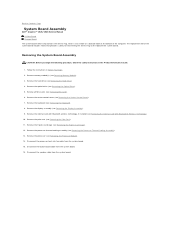
The replacement kit for the system board includes media that provides a utility for transferring the Service Tag to Contents Page System Board Assembly Dell™ Inspiron™ 1525/1526 Service Manual S-Video Board Charger Board The system board's BIOS chip contains the Service Tag, which is also ... the palm rest (see Removing the Processor Module). 14. Disconnect the speaker cable from the system board. 15. Remove the keyboard (see Removing the Internal Card With Bluetooth® Wireless Technology). 10. Remove the internal card with Bluetooth wireless technology, if installed (...
The replacement kit for the system board includes media that provides a utility for transferring the Service Tag to Contents Page System Board Assembly Dell™ Inspiron™ 1525/1526 Service Manual S-Video Board Charger Board The system board's BIOS chip contains the Service Tag, which is also ... the palm rest (see Removing the Processor Module). 14. Disconnect the speaker cable from the system board. 15. Remove the keyboard (see Removing the Internal Card With Bluetooth® Wireless Technology). 10. Remove the internal card with Bluetooth wireless technology, if installed (...
Service Manual
Page 48
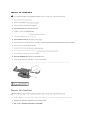
... board and seperate the S-Video board from the system board assembly. 1 screw 2 S-Video connector 3 S-Video board 4 system board Replacing the S-Video Board CAUTION: Before you begin the following procedure, follow the safety instructions in the Product Information Guide. 1. Remove the ... the Processor Thermal-Cooling Assembly). 13. Remove the processor thermal-cooling assembly (see Removing the Display Assembly). 9. Remove the keyboard (see Removing the Internal Card With Bluetooth® Wireless Technology). 10. Remove the internal card with Bluetooth wireless technology, if installed...
... board and seperate the S-Video board from the system board assembly. 1 screw 2 S-Video connector 3 S-Video board 4 system board Replacing the S-Video Board CAUTION: Before you begin the following procedure, follow the safety instructions in the Product Information Guide. 1. Remove the ... the Processor Thermal-Cooling Assembly). 13. Remove the processor thermal-cooling assembly (see Removing the Display Assembly). 9. Remove the keyboard (see Removing the Internal Card With Bluetooth® Wireless Technology). 10. Remove the internal card with Bluetooth wireless technology, if installed...


