Owners Manual
Page 27
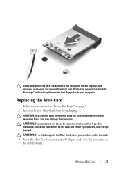
... information that shipped with your computer. If you use excessive force, you feel resistance, check the connectors on the card and on page 9. 2 Remove the new Mini-Card from its packaging. CAUTION: The connectors are keyed to the Mini-Card, never place cables under the card. 3 Insert the Mini-Card connector...
... information that shipped with your computer. If you use excessive force, you feel resistance, check the connectors on the card and on page 9. 2 Remove the new Mini-Card from its packaging. CAUTION: The connectors are keyed to the Mini-Card, never place cables under the card. 3 Insert the Mini-Card connector...
Owners Manual
Page 37
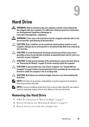
... On or in "Before You Begin" on page 13. 3 Remove the two screws from a source other than Dell, you need to the system board, remove the main battery, see "Removing the Battery" on the new hard drive. NOTE: If you remove the hard drive from sources other than... Dell. CAUTION: To prevent data loss, turn off your computer, see the Regulatory Compliance Homepage at www.dell.com/regulatory_compliance. Exercise care when handling the hard drive....
... On or in "Before You Begin" on page 13. 3 Remove the two screws from a source other than Dell, you need to the system board, remove the main battery, see "Removing the Battery" on the new hard drive. NOTE: If you remove the hard drive from sources other than... Dell. CAUTION: To prevent data loss, turn off your computer, see the Regulatory Compliance Homepage at www.dell.com/regulatory_compliance. Exercise care when handling the hard drive....
Owners Manual
Page 39
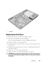
... Assembly" on the computer, replace all screws and ensure that no stray screws remain inside the computer. See "Replacing the Battery" on page 9. 2 Remove the new hard drive from step 3 to the computer. CAUTION: Before turning on page 32. 6 Replace the two screws to the computer base. 7 Replace the battery. Save...
... Assembly" on the computer, replace all screws and ensure that no stray screws remain inside the computer. See "Replacing the Battery" on page 9. 2 Remove the new hard drive from step 3 to the computer. CAUTION: Before turning on page 32. 6 Replace the two screws to the computer base. 7 Replace the battery. Save...
Owners Manual
Page 48
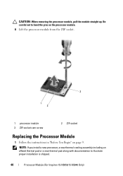
CAUTION: When removing the processor module, pull the module straight up. NOTE: If you install a new processor, a new thermal-cooling assembly including an affixed thermal pad or a new thermal pad along with documentation to bend the pins on the processor module. 6 Lift the processor module from the ZIF socket. 3 1 2 1 processor module 3 ZIF-socket cam screw 2 ZIF socket Replacing the Processor Module 1 Follow the instructions in "Before You Begin" on page 9. Be careful not to illustrate proper installation is shipped. 48 Processor Module (For Inspiron 15-N5050/15-N5040 Only)
CAUTION: When removing the processor module, pull the module straight up. NOTE: If you install a new processor, a new thermal-cooling assembly including an affixed thermal pad or a new thermal pad along with documentation to bend the pins on the processor module. 6 Lift the processor module from the ZIF socket. 3 1 2 1 processor module 3 ZIF-socket cam screw 2 ZIF socket Replacing the Processor Module 1 Follow the instructions in "Before You Begin" on page 9. Be careful not to illustrate proper installation is shipped. 48 Processor Module (For Inspiron 15-N5050/15-N5040 Only)


