
Inspiron 15 5000 Service Manual
Page 9
Removing the power-adapter port 104 Prerequisites 104 Procedure 104 Replacing the power-adapter port 106 Procedure 106 Post-requisites 106 Removing the palm rest and keyboard assembly.........108 Prerequisites 108 Procedure 109 Replacing the palm rest and keyboard assembly......... 110 Procedure 110 Post-requisites 110 Diagnostics 112 Getting help and contacting Dell 114 Self-help resources 114 Contacting Dell 114 9
Removing the power-adapter port 104 Prerequisites 104 Procedure 104 Replacing the power-adapter port 106 Procedure 106 Post-requisites 106 Removing the palm rest and keyboard assembly.........108 Prerequisites 108 Procedure 109 Replacing the palm rest and keyboard assembly......... 110 Procedure 110 Post-requisites 110 Diagnostics 112 Getting help and contacting Dell 114 Self-help resources 114 Contacting Dell 114 9

Inspiron 15 5000 Service Manual
Page 25
2 Place the base cover on the palm rest and keyboard assembly, and snap the base cover into place starting from the power-adapter port. 1 base cover 2 power-adapter port 3 Replace the screws that secure the base cover to the palm rest and keyboard assembly. GUID-65FDA1CD-4E26-4BA7-B1DF-FD73E839CF5A Post-requisites Replace the optical drive. 25
2 Place the base cover on the palm rest and keyboard assembly, and snap the base cover into place starting from the power-adapter port. 1 base cover 2 power-adapter port 3 Replace the screws that secure the base cover to the palm rest and keyboard assembly. GUID-65FDA1CD-4E26-4BA7-B1DF-FD73E839CF5A Post-requisites Replace the optical drive. 25

Inspiron 15 5000 Service Manual
Page 33
...wireless card Main (white triangle) Antenna-cable color White Auxiliary (black triangle) Black 4 Slide and replace the wireless-card bracket on the wireless-card slot. 5 Align the screw hole on the wireless...-card bracket with the tab on the wireless card and the palm rest and keyboard assembly. 33 GUID-89AE71F3-4BEC-4E5E-A9D0-E47D1BEE6532 Procedure CAUTION: To avoid damage to the wireless ...the wireless-card slot. 2 Insert the wireless card at www.dell.com/ regulatory_compliance. The following table provides the antenna-cable color scheme for the wireless card supported ...
...wireless card Main (white triangle) Antenna-cable color White Auxiliary (black triangle) Black 4 Slide and replace the wireless-card bracket on the wireless-card slot. 5 Align the screw hole on the wireless...-card bracket with the tab on the wireless card and the palm rest and keyboard assembly. 33 GUID-89AE71F3-4BEC-4E5E-A9D0-E47D1BEE6532 Procedure CAUTION: To avoid damage to the wireless ...the wireless-card slot. 2 Insert the wireless card at www.dell.com/ regulatory_compliance. The following table provides the antenna-cable color scheme for the wireless card supported ...

Inspiron 15 5000 Service Manual
Page 34
6 Replace the screw that secures the wireless-card bracket to the wireless card and the palm rest and keyboard assembly. 1 wireless card 3 wireless-card slot 5 antenna cables (2) 7 wireless-card bracket 2 notch 4 tab 6 M2x3 screw 34
6 Replace the screw that secures the wireless-card bracket to the wireless card and the palm rest and keyboard assembly. 1 wireless card 3 wireless-card slot 5 antenna cables (2) 7 wireless-card bracket 2 notch 4 tab 6 M2x3 screw 34

Inspiron 15 5000 Service Manual
Page 38
... practices, see the Regulatory Compliance home page at www.dell.com/ regulatory_compliance. GUID-C6F8A5A3-0E1D-447A-B2A2-15472E17B739 Procedure 1 Align the screw holes on the palm rest and keyboard assembly. 2 Replace the screws that secure the optical-drive interposer to the palm rest and keyboard assembly. 3 Connect the optical-drive interposer cable to the...
... practices, see the Regulatory Compliance home page at www.dell.com/ regulatory_compliance. GUID-C6F8A5A3-0E1D-447A-B2A2-15472E17B739 Procedure 1 Align the screw holes on the palm rest and keyboard assembly. 2 Replace the screws that secure the optical-drive interposer to the palm rest and keyboard assembly. 3 Connect the optical-drive interposer cable to the...

Inspiron 15 5000 Service Manual
Page 41
... cable through the routing guide on the palm rest and keyboard assembly. 3 Connect the coin-cell battery cable to the system board. GUID-FC885216-4D9B-490B-8E29-934447E8E5D4 Post-requisites 1 Replace the base cover. 2 Replace the optical drive. 41 For more safety best practices, ...see the Regulatory Compliance home page at www.dell.com/ regulatory_compliance. After working inside your computer, follow the steps in...
... cable through the routing guide on the palm rest and keyboard assembly. 3 Connect the coin-cell battery cable to the system board. GUID-FC885216-4D9B-490B-8E29-934447E8E5D4 Post-requisites 1 Replace the base cover. 2 Replace the optical drive. 41 For more safety best practices, ...see the Regulatory Compliance home page at www.dell.com/ regulatory_compliance. After working inside your computer, follow the steps in...

Inspiron 15 5000 Service Manual
Page 44
... Regulatory Compliance home page at www.dell.com/ regulatory_compliance. GUID-6F09C935-27D9-45D4-AFD9-6B73D50DC0FA Procedure 1 Using the alignment posts, place the I/O board on the palm rest and keyboard assembly. 2 Align the screw hole on the I/O board with the screw hole on the palm rest and keyboard assembly. 3 Replace the screw that secures the...
... Regulatory Compliance home page at www.dell.com/ regulatory_compliance. GUID-6F09C935-27D9-45D4-AFD9-6B73D50DC0FA Procedure 1 Using the alignment posts, place the I/O board on the palm rest and keyboard assembly. 2 Align the screw hole on the I/O board with the screw hole on the palm rest and keyboard assembly. 3 Replace the screw that secures the...

Inspiron 15 5000 Service Manual
Page 48
...DEF249B135F8 Procedure 1 Align the screw holes on the hard-drive bracket with the screw holes on the hard drive. 2 Replace the screws that secure the hard-drive bracket to the hard drive. 3 Connect the interposer to the hard-drive assembly.... 4 Align the screw holes on the palm rest and keyboard assembly. 5 Replace the screws that shipped with the screw holes on the hard-drive assembly with your computer and follow the ...For more safety best practices, see the Regulatory Compliance home page at www.dell.com/ regulatory_compliance.
...DEF249B135F8 Procedure 1 Align the screw holes on the hard-drive bracket with the screw holes on the hard drive. 2 Replace the screws that secure the hard-drive bracket to the hard drive. 3 Connect the interposer to the hard-drive assembly.... 4 Align the screw holes on the palm rest and keyboard assembly. 5 Replace the screws that shipped with the screw holes on the hard-drive assembly with your computer and follow the ...For more safety best practices, see the Regulatory Compliance home page at www.dell.com/ regulatory_compliance.

Inspiron 15 5000 Service Manual
Page 52
...read the safety information that secure the battery bracket to the palm rest and keyboard assembly. 3 Align the screw holes on the system board and palm rest and keyboard assembly. 4 Replace the screws that shipped with the screw holes on the battery bracket with your.... GUID-ADB6AB7C-464F-4F3F-AD1C-B142692E04D4 Post-requisites 1 Replace the hard drive. 2 Replace the I/O board. 3 Replace the base cover. 4 Replace the optical drive. 52 For more safety best practices, see the Regulatory Compliance home page at www.dell.com/ regulatory_compliance. After working inside your computer, follow...
...read the safety information that secure the battery bracket to the palm rest and keyboard assembly. 3 Align the screw holes on the system board and palm rest and keyboard assembly. 4 Replace the screws that shipped with the screw holes on the battery bracket with your.... GUID-ADB6AB7C-464F-4F3F-AD1C-B142692E04D4 Post-requisites 1 Replace the hard drive. 2 Replace the I/O board. 3 Replace the base cover. 4 Replace the optical drive. 52 For more safety best practices, see the Regulatory Compliance home page at www.dell.com/ regulatory_compliance. After working inside your computer, follow...
Inspiron 15 5000 Service Manual
Page 55
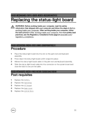
... 2 Press down the status-light board until it snaps into place. 3 Adhere the status-light board cable to the palm rest and keyboard assembly. 4 Slide the status-light board cable into the connector on the system board and close the latch to secure the cable. For... more safety best practices, see the Regulatory Compliance home page at www.dell.com/ regulatory_compliance. GUID-8EDA8A82-09F4-420D-8DE0-82220E44E1C2 Replacing the status-light board WARNING: Before working inside your computer, read the safety information that shipped with your computer ...
... 2 Press down the status-light board until it snaps into place. 3 Adhere the status-light board cable to the palm rest and keyboard assembly. 4 Slide the status-light board cable into the connector on the system board and close the latch to secure the cable. For... more safety best practices, see the Regulatory Compliance home page at www.dell.com/ regulatory_compliance. GUID-8EDA8A82-09F4-420D-8DE0-82220E44E1C2 Replacing the status-light board WARNING: Before working inside your computer, read the safety information that shipped with your computer ...
Inspiron 15 5000 Service Manual
Page 58
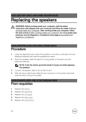
For more safety best practices, see the Regulatory Compliance home page at www.dell.com/ regulatory_compliance. GUID-40DC76F7-B3EC-450A-848E-632D68C352E2 Replacing the speakers WARNING: Before working inside your computer, read the safety information that shipped with your ... slots on the palm rest and keyboard assembly and snap the speakers into the connector on the palm rest and keyboard assembly. GUID-1F9A097D-6ED1-4162-8C96-329D29AC0D98 Post-requisites 1 Replace the battery. 2 Replace the hard drive. 3 Replace the I/O board. 4 Replace the base cover. 5 Replace the optical drive. 58
For more safety best practices, see the Regulatory Compliance home page at www.dell.com/ regulatory_compliance. GUID-40DC76F7-B3EC-450A-848E-632D68C352E2 Replacing the speakers WARNING: Before working inside your computer, read the safety information that shipped with your ... slots on the palm rest and keyboard assembly and snap the speakers into the connector on the palm rest and keyboard assembly. GUID-1F9A097D-6ED1-4162-8C96-329D29AC0D98 Post-requisites 1 Replace the battery. 2 Replace the hard drive. 3 Replace the I/O board. 4 Replace the base cover. 5 Replace the optical drive. 58

Inspiron 15 5000 Service Manual
Page 64
... speaker cable and coin-cell battery cable into the connectors on the palm and keyboard rest assembly. 6 Replace the screw that secures the system board to the palm rest and keyboard assembly. 7 Replace the screw that shipped with the screw hole on the system board. 64 You...working inside your computer. For more safety best practices, see the Regulatory Compliance home page at www.dell.com/ regulatory_compliance. GUID-828BE30D-72EC-4782-A72D-288087A2AB2F Replacing the system-board assembly WARNING: Before working inside your computer, read the safety information that secures the...
... speaker cable and coin-cell battery cable into the connectors on the palm and keyboard rest assembly. 6 Replace the screw that secures the system board to the palm rest and keyboard assembly. 7 Replace the screw that shipped with the screw hole on the system board. 64 You...working inside your computer. For more safety best practices, see the Regulatory Compliance home page at www.dell.com/ regulatory_compliance. GUID-828BE30D-72EC-4782-A72D-288087A2AB2F Replacing the system-board assembly WARNING: Before working inside your computer, read the safety information that secures the...
Inspiron 15 5000 Service Manual
Page 65
9 Slide the touch-pad cable, keyboard backlight cable, and keyboard cable into the connectors and close the latches. 10 Slide the status-light board cable into the connector on the system board and close ...Connect the display cable to the system board. 15 Replace the screws that secure the right display hinge to the palm rest and keyboard assembly. GUID-F95B5498-F2B9-416B-95E4-296FC791E7D1 Post-requisites 1 Replace the wireless card. 2 Replace the memory modules. 3 Replace the battery. 4 Replace the hard drive. 5 Replace the I/O board. 6 Replace the base cover. 7 Replace the optical drive. 65
9 Slide the touch-pad cable, keyboard backlight cable, and keyboard cable into the connectors and close the latches. 10 Slide the status-light board cable into the connector on the system board and close ...Connect the display cable to the system board. 15 Replace the screws that secure the right display hinge to the palm rest and keyboard assembly. GUID-F95B5498-F2B9-416B-95E4-296FC791E7D1 Post-requisites 1 Replace the wireless card. 2 Replace the memory modules. 3 Replace the battery. 4 Replace the hard drive. 5 Replace the I/O board. 6 Replace the base cover. 7 Replace the optical drive. 65

Inspiron 15 5000 Service Manual
Page 74
...Replacing the touch pad WARNING: Before working inside your computer, read the safety information that secures the touch pad to the palm rest and keyboard... assembly. 7 Slide both ends of the touch pad is aligned with the guides available on the palm-rest and keyboard... to secure the cable. 8 Slide the keyboard backlight cable into the connector and close the...rest and keyboard assembly. 2 Replace the screws that secure the touch pad to the palm rest and keyboard assembly. 3...and keyboard assembly. 5 Replace the screws that secure the touch-pad bracket to the palm rest and keyboard assembly...
...Replacing the touch pad WARNING: Before working inside your computer, read the safety information that secures the touch pad to the palm rest and keyboard... assembly. 7 Slide both ends of the touch pad is aligned with the guides available on the palm-rest and keyboard... to secure the cable. 8 Slide the keyboard backlight cable into the connector and close the...rest and keyboard assembly. 2 Replace the screws that secure the touch pad to the palm rest and keyboard assembly. 3...and keyboard assembly. 5 Replace the screws that secure the touch-pad bracket to the palm rest and keyboard assembly...

Inspiron 15 5000 Service Manual
Page 80
...safety best practices, see the Regulatory Compliance home page at www.dell.com/ regulatory_compliance. After working inside your computer, follow the steps in After working inside your computer. GUID-2DF70EB1-9D26-4051-8B7C-FB14A89925D8 Replacing the display assembly WARNING: Before working inside your computer, read ... and close the latch to secure the cable. 6 Slide the battery cable to the connector on the palm rest and keyboard assembly. 3 Replace the screws that shipped with your computer and follow the instructions in Before working inside your computer. GUID-75473F2A-D495-4825-...
...safety best practices, see the Regulatory Compliance home page at www.dell.com/ regulatory_compliance. After working inside your computer, follow the steps in After working inside your computer. GUID-2DF70EB1-9D26-4051-8B7C-FB14A89925D8 Replacing the display assembly WARNING: Before working inside your computer, read ... and close the latch to secure the cable. 6 Slide the battery cable to the connector on the palm rest and keyboard assembly. 3 Replace the screws that shipped with your computer and follow the instructions in Before working inside your computer. GUID-75473F2A-D495-4825-...
Inspiron 15 5000 Service Manual
Page 102
...keyboard assembly. GUID-354835A2-18DD-4B65-AFD4-8D21647BC5EE Post-requisites 1 Replace the display panel. 2 Replace the heat-sink assembly. 3 Replace the system-board assembly. 4 Replace the wireless card. 5 Replace the memory modules. 6 Replace the battery. 7 Replace... the hard drive. 102 GUID-1742A3A3-E83D-4D87-91DA-569382711ACA Replacing...the palm rest and keyboard assembly. 4 Replace the screw that ...
...keyboard assembly. GUID-354835A2-18DD-4B65-AFD4-8D21647BC5EE Post-requisites 1 Replace the display panel. 2 Replace the heat-sink assembly. 3 Replace the system-board assembly. 4 Replace the wireless card. 5 Replace the memory modules. 6 Replace the battery. 7 Replace... the hard drive. 102 GUID-1742A3A3-E83D-4D87-91DA-569382711ACA Replacing...the palm rest and keyboard assembly. 4 Replace the screw that ...

Inspiron 15 5000 Service Manual
Page 106
... Post-requisites 1 Replace the display panel. 2 Replace the heat-sink assembly. 3 Replace the system-board assembly. 4 Replace the wireless card. 5 Replace the memory modules. 6 Replace the status-light board. 106 For more safety best practices, see the Regulatory Compliance home page at www.dell.com/ regulatory_compliance. ...the safety information that shipped with the screw hole on the palm rest and keyboard assembly. 3 Replace the screw that secures the power-adapter port to the palm rest and keyboard assembly. 4 Route the power-adapter port cable through the routing guides on ...
... Post-requisites 1 Replace the display panel. 2 Replace the heat-sink assembly. 3 Replace the system-board assembly. 4 Replace the wireless card. 5 Replace the memory modules. 6 Replace the status-light board. 106 For more safety best practices, see the Regulatory Compliance home page at www.dell.com/ regulatory_compliance. ...the safety information that shipped with the screw hole on the palm rest and keyboard assembly. 3 Replace the screw that secures the power-adapter port to the palm rest and keyboard assembly. 4 Route the power-adapter port cable through the routing guides on ...

Inspiron 15 5000 Service Manual
Page 110
For more safety best practices, see the Regulatory Compliance home page at www.dell.com/ regulatory_compliance. GUID-A7F798E1-C24C-44A0-9D6E-60A24BC170F6 Replacing the palm rest and keyboard assembly WARNING: Before working inside your computer, read the safety information that shipped with your computer and follow the instructions in Before working inside your ...
For more safety best practices, see the Regulatory Compliance home page at www.dell.com/ regulatory_compliance. GUID-A7F798E1-C24C-44A0-9D6E-60A24BC170F6 Replacing the palm rest and keyboard assembly WARNING: Before working inside your computer, read the safety information that shipped with your computer and follow the instructions in Before working inside your ...


