
Service Manual
Page 3
...Entering Service Mode...6 Safety instructions...6 Electrostatic discharge-ESD protection...7 ESD field service kit ...8 Transporting sensitive components...9 Exiting Service Mode...9 After working inside your computer...9 Chapter 2: Removing and installing components 10 Recommended tools...10 Screw list...10 Major components of Inspiron 14 5420...11 Base cover...13 Removing the base cover...13 Installing the base cover...16 Battery cable...17 Removing the battery cable...17 Installing the battery cable...18 Battery...19 Lithium-ion battery precautions...19 Removing the battery...20 Installing...
...Entering Service Mode...6 Safety instructions...6 Electrostatic discharge-ESD protection...7 ESD field service kit ...8 Transporting sensitive components...9 Exiting Service Mode...9 After working inside your computer...9 Chapter 2: Removing and installing components 10 Recommended tools...10 Screw list...10 Major components of Inspiron 14 5420...11 Base cover...13 Removing the base cover...13 Installing the base cover...16 Battery cable...17 Removing the battery cable...17 Installing the battery cable...18 Battery...19 Lithium-ion battery precautions...19 Removing the battery...20 Installing...

Service Manual
Page 4
... setup password...66 Assigning a system setup password...66 Deleting or changing an existing system setup password 67 Clearing CMOS settings...67 Clearing BIOS (System Setup) and System passwords 68 Updating the BIOS...68 Updating the BIOS in Windows...68 Updating the BIOS using the USB drive in Windows 68 Updating the BIOS in Linux and Ubuntu...68 Updating the BIOS from the F12 One-Time boot menu 69 Chapter 5: Troubleshooting...70 Handling swollen Lithium-ion batteries...70 Locate the Service Tag or Express Service Code of your Dell...
... setup password...66 Assigning a system setup password...66 Deleting or changing an existing system setup password 67 Clearing CMOS settings...67 Clearing BIOS (System Setup) and System passwords 68 Updating the BIOS...68 Updating the BIOS in Windows...68 Updating the BIOS using the USB drive in Windows 68 Updating the BIOS in Linux and Ubuntu...68 Updating the BIOS from the F12 One-Time boot menu 69 Chapter 5: Troubleshooting...70 Handling swollen Lithium-ion batteries...70 Locate the Service Tag or Express Service Code of your Dell...

Service Manual
Page 6
.... Disconnect all attached network devices and peripherals, such as keyboard, mouse, and monitor from the system board. Entering Service Mode Service Mode allows users to -proceed message appears on the screen. Press any key to proceed. Safety instructions Use the following step if the Owner Tag of your computer, if applicable. Disconnect your personal safety. Remove any key to continue the Service Mode procedure. NOTE: If you are using a different operating system, see...
.... Disconnect all attached network devices and peripherals, such as keyboard, mouse, and monitor from the system board. Entering Service Mode Service Mode allows users to -proceed message appears on the screen. Press any key to proceed. Safety instructions Use the following step if the Owner Tag of your computer, if applicable. Disconnect your personal safety. Remove any key to continue the Service Mode procedure. NOTE: If you are using a different operating system, see...

Service Manual
Page 7
... may not be replaced and disposed properly. The use anti-static floor pads and workbench pads. they do not provide adequate protection. For more difficult type of device functionality. CAUTION: Press and eject any installed card from all power sources before handling parts does not ensure adequate ESD protection on parts with your computer. Two recognized types of memory integrity, intermittent memory errors, etc. CAUTION: You...
... may not be replaced and disposed properly. The use anti-static floor pads and workbench pads. they do not provide adequate protection. For more difficult type of device functionality. CAUTION: Press and eject any installed card from all power sources before handling parts does not ensure adequate ESD protection on parts with your computer. Two recognized types of memory integrity, intermittent memory errors, etc. CAUTION: You...

Service Manual
Page 9
... return to turn on your computer. 2. Steps 1. Working inside your computer may severely damage your computer. 3. After working on your computer. Replace any media cards, discs, or any external devices, peripherals, or cables you lift, offsetting the force of your back. 5. Always obtain additional resources or use a mechanical lifting device. 1. Abdominal muscles support your computer. Press the power button to normal functioning mode. Connect any other parts that no...
... return to turn on your computer. 2. Steps 1. Working inside your computer may severely damage your computer. 3. After working on your computer. Replace any media cards, discs, or any external devices, peripherals, or cables you lift, offsetting the force of your back. 5. Always obtain additional resources or use a mechanical lifting device. 1. Abdominal muscles support your computer. Press the power button to normal functioning mode. Connect any other parts that no...
Service Manual
Page 28
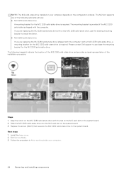
... M.2 2280 solid-state drive into the M.2 card slot on the system board. 2. Install the base cover. 2. Exit Service Mode. 3. Please contact Dell support to purchase the mounting bracket for the M.2 2230 solid-state drive is required. NOTE: The M.2 solid-state drive installed on your computer. 28 Removing and installing components Follow the procedure in After working inside your computer depends on the configuration ordered. The M.2 slot supports one of the...
... M.2 2280 solid-state drive into the M.2 card slot on the system board. 2. Install the base cover. 2. Exit Service Mode. 3. Please contact Dell support to purchase the mounting bracket for the M.2 2230 solid-state drive is required. NOTE: The M.2 solid-state drive installed on your computer. 28 Removing and installing components Follow the procedure in After working inside your computer depends on the configuration ordered. The M.2 slot supports one of the...
Service Manual
Page 34
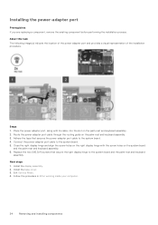
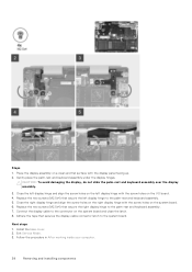
... the installation procedure. Connect the power-adapter port cable to the system board and the palm-rest and keyboard assembly. Replace the two (M2.5x4) screws that secures the power-adapter port cable to the system board. 4. Exit Service Mode. 4. Route the power-adapter port cable through the routing guide on the palm-rest and keyboard assembly. 2. Adhere the tape that secure the right display hinge to the system board. 5. Install the base cover. 3. Installing the power-adapter port Prerequisites...
... the installation procedure. Connect the power-adapter port cable to the system board and the palm-rest and keyboard assembly. Replace the two (M2.5x4) screws that secures the power-adapter port cable to the system board. 4. Exit Service Mode. 4. Route the power-adapter port cable through the routing guide on the palm-rest and keyboard assembly. 2. Adhere the tape that secure the right display hinge to the system board. 5. Install the base cover. 3. Installing the power-adapter port Prerequisites...
Service Manual
Page 38
... the screw holes on the left display hinge to the palm-rest and keyboard assembly. 7. Connect the display cable to the system board. Install the base cover. 2. Steps 1. Replace the two screws (M2.5x4) that secure the left display hinge with the display panel facing up. 2. Follow the procedure in After working inside your computer. 38 Removing and installing components Replace the two screws (M2.5x4...
... the screw holes on the left display hinge to the palm-rest and keyboard assembly. 7. Connect the display cable to the system board. Install the base cover. 2. Steps 1. Replace the two screws (M2.5x4) that secure the left display hinge with the display panel facing up. 2. Follow the procedure in After working inside your computer. 38 Removing and installing components Replace the two screws (M2.5x4...
Service Manual
Page 40
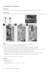
... optional fingerprint reader. 9. Next steps 1. Install the display assembly. 2. Steps 1. Connect the power button with fingerprint-reader cable to the I /O board and close the latch. 8. Connect the coin-cell battery cable to the connector on the palm-rest and keyboard assembly. 4. Follow the procedure in After working inside your computer. 40 Removing and installing components Replace the two screws (M2.5x4) that secures the I /O board to the slots on the I /O board...
... optional fingerprint reader. 9. Next steps 1. Install the display assembly. 2. Steps 1. Connect the power button with fingerprint-reader cable to the I /O board and close the latch. 8. Connect the coin-cell battery cable to the connector on the palm-rest and keyboard assembly. 4. Follow the procedure in After working inside your computer. 40 Removing and installing components Replace the two screws (M2.5x4) that secures the I /O board to the slots on the I /O board...

Service Manual
Page 52
... After working inside your computer. Remove the memory module. 4. Remove the speakers. 7. Replace the screw (M2x3) that secures the power button with optional fingerprint reader on your computer. 2. Install the base cover. 3. About this task The following image indicates the connectors on the palm-rest and keyboard assembly. 2. Exit Service Mode. 4. Remove the base cover. 3. Remove the M.2 2230 solid-state drive or M.2 2280 solid-state drive. 5. Remove the wireless card. 6. Install the I/O board. 2. System board Removing the system board...
... After working inside your computer. Remove the memory module. 4. Remove the speakers. 7. Replace the screw (M2x3) that secures the power button with optional fingerprint reader on your computer. 2. Install the base cover. 3. About this task The following image indicates the connectors on the palm-rest and keyboard assembly. 2. Exit Service Mode. 4. Remove the base cover. 3. Remove the M.2 2230 solid-state drive or M.2 2280 solid-state drive. 5. Remove the wireless card. 6. Install the I/O board. 2. System board Removing the system board...

Service Manual
Page 57
.... 2. Remove the wireless card. 7. Remove the power button. 12. Remove the M.2 2230 solid-state drive or M.2 2280 solid-state drive. 6. Replace the two screws (M2x4) that secures the I /O-board cable to the system board and close the latch to the system board and close the latch. 14. Install the base cover. 7. Remove the battery. 4. Remove the display assembly. 6. Follow the procedure in Before working inside your computer. Remove the memory module. 5. Next steps 1. Connect the touchpad cable to...
.... 2. Remove the wireless card. 7. Remove the power button. 12. Remove the M.2 2230 solid-state drive or M.2 2280 solid-state drive. 6. Replace the two screws (M2x4) that secures the I /O-board cable to the system board and close the latch to the system board and close the latch. 14. Install the base cover. 7. Remove the battery. 4. Remove the display assembly. 6. Follow the procedure in Before working inside your computer. Remove the memory module. 5. Next steps 1. Connect the touchpad cable to...

Service Manual
Page 61
... of RAM and the size of the hard drive. ● Change the system configuration information. ● Set or change a user-selectable option, such as the user password, type of the System Setup options, changes that you make your computer and try again. Entering BIOS setup program Steps 1. Turn on the computer and its installed devices, the items listed in the main screen displays a message that prompts you view the main screen. Then, turn off your computer work incorrectly...
... of RAM and the size of the hard drive. ● Change the system configuration information. ● Set or change a user-selectable option, such as the user password, type of the System Setup options, changes that you make your computer and try again. Entering BIOS setup program Steps 1. Turn on the computer and its installed devices, the items listed in the main screen displays a message that prompts you view the main screen. Then, turn off your computer work incorrectly...

Service Manual
Page 64
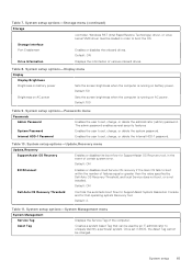
... audio controller. Default: RAID On. Storage device is selected. Custom Mode Key Management Allows for selection of the integrated storage device controller. USB Configuration Enables or disables booting from USB mass storage devices such as external hard drive, optical drive, and USB drive. System setup options-Storage menu Storage SATA/NVMe Operation SATA/NVMe Operation Configures operating mode of key database. ● Save to File will save the key to support RAID functions. Default: ON Enable Microphone Enables or disables microphone. Table 7. Changes...
... audio controller. Default: RAID On. Storage device is selected. Custom Mode Key Management Allows for selection of the integrated storage device controller. USB Configuration Enables or disables booting from USB mass storage devices such as external hard drive, optical drive, and USB drive. System setup options-Storage menu Storage SATA/NVMe Operation SATA/NVMe Operation Configures operating mode of key database. ● Save to File will save the key to support RAID functions. Default: ON Enable Microphone Enables or disables microphone. Table 7. Changes...
Service Manual
Page 65
... set , change, or delete the Internal HDD-1 password. Windows RST (Intel Rapid Restore Technology) driver, or Linux kernel VMD driver must be used by Dell Auto OS Recovery Threshold, and local Service does not boot, or is running on AC power Sets the screen brightness when the computer is not installed. Storage Interface Port Enablement Enables or disables the onboard drives. System setup 65 Internal HDD-1 Password Enables the user to boot within the number of various onboard drives. Default: 2. Table 8. Default: ON Drive Information Displays the...
... set , change, or delete the Internal HDD-1 password. Windows RST (Intel Rapid Restore Technology) driver, or Linux kernel VMD driver must be used by Dell Auto OS Recovery Threshold, and local Service does not boot, or is running on AC power Sets the screen brightness when the computer is not installed. Storage Interface Port Enablement Enables or disables the onboard drives. System setup 65 Internal HDD-1 Password Enables the user to boot within the number of various onboard drives. Default: 2. Table 8. Default: ON Drive Information Displays the...

Service Manual
Page 67
.... Type the system password that Password Status is displayed. 2. The computer restarts. If you change an existing System or Setup password, if the Password Status is displayed. 2. Press Esc and a message prompts you entered earlier in the Confirm new password field and click OK. 4. The Security screen is Unlocked. 3. Select System Password, update, or delete the existing system password, and press Enter or Tab. 4. Remove the coin-cell battery. 4. Steps 1. Enter Service Mode...
.... Type the system password that Password Status is displayed. 2. The computer restarts. If you change an existing System or Setup password, if the Password Status is displayed. 2. Press Esc and a message prompts you entered earlier in the Confirm new password field and click OK. 4. The Security screen is Unlocked. 3. Select System Password, update, or delete the existing system password, and press Enter or Tab. 4. Remove the coin-cell battery. 4. Steps 1. Enter Service Mode...
Service Manual
Page 68
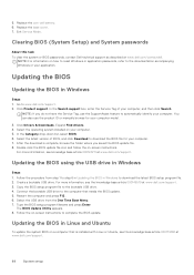
... Enter. Replace the coin-cell battery. 6. In the Search support box, enter the Service Tag of BIOS, and click Download to download the latest BIOS setup program file. 2. Updating the BIOS using the USB drive in Windows Steps 1. Restart the computer and press F12 . 6. Updating the BIOS in Windows to download the BIOS file for your application. Replace the base cover. 7. Select the operating system installed on a computer that needs the BIOS update. 5. Follow the on -screen instructions. Updating the BIOS Updating the BIOS in Windows...
... Enter. Replace the coin-cell battery. 6. In the Search support box, enter the Service Tag of BIOS, and click Download to download the latest BIOS setup program file. 2. Updating the BIOS using the USB drive in Windows Steps 1. Restart the computer and press F12 . 6. Updating the BIOS in Windows to download the BIOS file for your application. Replace the base cover. 7. Select the operating system installed on a computer that needs the BIOS update. 5. Follow the on -screen instructions. Updating the BIOS Updating the BIOS in Windows...

Service Manual
Page 69
... the BIOS update is displayed. 3. Select external USB device. 5. The computer will restart after 2012 have to be bootable) ● BIOS executable file that you downloaded from the Dell Support website and copied to the root of the USB drive ● AC power adapter that is listed as a boot option for your BIOS from the F12 One-Time boot menu, you need the following steps to access the One-Time Boot Menu, select BIOS Update using a bootable USB drive...
... the BIOS update is displayed. 3. Select external USB device. 5. The computer will restart after 2012 have to be bootable) ● BIOS executable file that you downloaded from the Dell Support website and copied to the root of the USB drive ● AC power adapter that is listed as a boot option for your BIOS from the F12 One-Time boot menu, you need the following steps to access the One-Time Boot Menu, select BIOS Update using a bootable USB drive...
Service Manual
Page 72
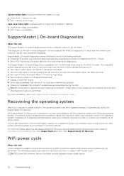
... Lock status light: Indicates whether Caps Lock is the new on-board diagnostic tool and replaces the ePSA 3.0 diagnostics. Recovering the operating system When your computer is launched by one -time Boot Menu and selecting Diagnostics to provide extra information about the Dell SupportAssist OS Recovery, see SupportAssist Pre-Boot System Performance Check. Dell SupportAssist OS Recovery is a standalone tool that is preinstalled in either Quick Test Mode...
... Lock status light: Indicates whether Caps Lock is the new on-board diagnostic tool and replaces the ePSA 3.0 diagnostics. Recovering the operating system When your computer is launched by one -time Boot Menu and selecting Diagnostics to provide extra information about the Dell SupportAssist OS Recovery, see SupportAssist Pre-Boot System Performance Check. Dell SupportAssist OS Recovery is a standalone tool that is preinstalled in either Quick Test Mode...
Setup and Specifications
Page 4
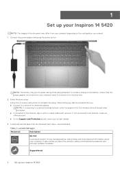
... charge on -screen instructions to your computer. SupportAssist 4 Set up , Dell recommends that the power adapter is connected to complete the setup. Ensure that you about your computer when it is turned on the configuration you ordered. 1. When setting up your contact details. 3. It also notifies you : ● Connect to the Internet, create an offline account. ● On the Support and Protection screen, enter your Inspiron 14 5420 If not connected to a network for key Dell...
... charge on -screen instructions to your computer. SupportAssist 4 Set up , Dell recommends that the power adapter is connected to complete the setup. Ensure that you about your computer when it is turned on the configuration you ordered. 1. When setting up your contact details. 3. It also notifies you : ● Connect to the Internet, create an offline account. ● On the Support and Protection screen, enter your Inspiron 14 5420 If not connected to a network for key Dell...

Setup and Specifications
Page 6
... of Inspiron 14 5420 Left 1. Solid amber-Battery charge is fully charged. For more information, see the Troubleshooting section in enabled device. Provides video and audio output. 4. Provides data transfer rate of the computer. NOTE: A USB Type-C to 15 W power output that enables two-way power supply between devices. HDMI 1.4 port Connect to the SD card. Provides data transfer speeds up to DisplayPort adapter (sold separately) is charging. Provides up to your computer's Service Manual. 3. Supports Power...
... of Inspiron 14 5420 Left 1. Solid amber-Battery charge is fully charged. For more information, see the Troubleshooting section in enabled device. Provides video and audio output. 4. Provides data transfer rate of the computer. NOTE: A USB Type-C to 15 W power output that enables two-way power supply between devices. HDMI 1.4 port Connect to the SD card. Provides data transfer speeds up to DisplayPort adapter (sold separately) is charging. Provides up to your computer's Service Manual. 3. Supports Power...


