

Service Guide
Page 5
Contents Preface...ix Warnings and Cautions xiii Chapter 1 The IP4700 About the IP4700 1-2 IP4700 Components 1-4 Customer-Replaceable Units (CRUs 1-4 High-Availability Features 1-5 Enclosure 1-6 Front Panel 1-7 Front Door 1-9 Midplane 1-9 Storage Processors 1-10 Link Control Cards (LCCs 1-12 Disk Modules 1-13 Disk Drives 1-13 ...
Contents Preface...ix Warnings and Cautions xiii Chapter 1 The IP4700 About the IP4700 1-2 IP4700 Components 1-4 Customer-Replaceable Units (CRUs 1-4 High-Availability Features 1-5 Enclosure 1-6 Front Panel 1-7 Front Door 1-9 Midplane 1-9 Storage Processors 1-10 Link Control Cards (LCCs 1-12 Disk Modules 1-13 Disk Drives 1-13 ...
Service Guide
Page 6
... 3 Servicing and Upgrading an IP4700 Monitoring IP4700 Status 3-2 Handling CRUs 3-5 Power Issues and CRUs 3-5 Avoiding Electrostatic Discharge (ESD) Damage 3-6 Replacing or Adding a Disk Module 3-8 Replacing the Storage Processor Fan Pack 3-13 Replacing a Storage Processor 3-15 Installing a Storage Processor 3-16 Replacing a Link Control Card 3-17 Replacing the Drive Fan Pack 3-20 Replacing a Power Supply Module 3-23 Replacing an SPS 3-28...
... 3 Servicing and Upgrading an IP4700 Monitoring IP4700 Status 3-2 Handling CRUs 3-5 Power Issues and CRUs 3-5 Avoiding Electrostatic Discharge (ESD) Damage 3-6 Replacing or Adding a Disk Module 3-8 Replacing the Storage Processor Fan Pack 3-13 Replacing a Storage Processor 3-15 Installing a Storage Processor 3-16 Replacing a Link Control Card 3-17 Replacing the Drive Fan Pack 3-20 Replacing a Power Supply Module 3-23 Replacing an SPS 3-28...

Service Guide
Page 9
... for technical personnel and system administrators who will install and service the IP4700, you intend to • install an IP4700 • upgrade an IP4700 by adding disk modules and disk-array enclosures (DAEs) • replace failed CRUs • install, service, and use the DC Standby ...Power Supply (DC SPS) IP4700 Installation and Service Guide ix Preface This manual explains how to install the IP4700, install or replace the Standby Power Supply (SPS), and how to replace customer-replaceable units (CRUs). If you have installed the appropriate mounting ...
... for technical personnel and system administrators who will install and service the IP4700, you intend to • install an IP4700 • upgrade an IP4700 by adding disk modules and disk-array enclosures (DAEs) • replace failed CRUs • install, service, and use the DC Standby ...Power Supply (DC SPS) IP4700 Installation and Service Guide ix Preface This manual explains how to install the IP4700, install or replace the Standby Power Supply (SPS), and how to replace customer-replaceable units (CRUs). If you have installed the appropriate mounting ...

Service Guide
Page 10
...Chapter 3 describes how to the system or equipment. In addition, it to the LAN and to replace the SPS. Chapter 2 explains requirements and describes how to install the IP4700 and cable it explains how to Disk Array Enclosures (DAEs). Chapter 4 introduces the Standby Power ...and explains how to install and connect cables to hardware or software. Appendix A lists the IP4700 and SPS technical specifications. Glossary defines terms used in this manual: Chapter 1 introduces the IP4700's components. The caution may apply to them. Other related manuals include: • EMC ...
...Chapter 3 describes how to the system or equipment. In addition, it to the LAN and to replace the SPS. Chapter 2 explains requirements and describes how to install the IP4700 and cable it explains how to Disk Array Enclosures (DAEs). Chapter 4 introduces the Standby Power ...and explains how to install and connect cables to hardware or software. Appendix A lists the IP4700 and SPS technical specifications. Glossary defines terms used in this manual: Chapter 1 introduces the IP4700's components. The caution may apply to them. Other related manuals include: • EMC ...

Service Guide
Page 16
Warnings and Cautions WARNING EMC apoya la instalación, mantenimiento y expansión de estos sistemas solamente por medio de proveedores de servicio calificados. xvi IP4700 Installation and Service Guide CAUTION Trained personnel are advised to exercise great care at all paperwork, including incident reports, up to : • Remove rings, watches, ...;s información sobre las garantías a fan, motor, or solenoid. • Always use the correct tools for the job. • Always use the correct replacement parts. • Keep all times when working on the...
Warnings and Cautions WARNING EMC apoya la instalación, mantenimiento y expansión de estos sistemas solamente por medio de proveedores de servicio calificados. xvi IP4700 Installation and Service Guide CAUTION Trained personnel are advised to exercise great care at all paperwork, including incident reports, up to : • Remove rings, watches, ...;s información sobre las garantías a fan, motor, or solenoid. • Always use the correct tools for the job. • Always use the correct replacement parts. • Keep all times when working on the...

Service Guide
Page 17
... a printed-circuit board. • Unless specifically designed for non-disruptive replacement, never plug or unplug printed-circuit boards with the power on. IP4700 Installation and Service Guide xvii Severe component damage may result. CAUTION Before handling IP4700 printed-circuit boards or other IP4700 parts containing LSI and/or VLSI components, observe the following precautions...
... a printed-circuit board. • Unless specifically designed for non-disruptive replacement, never plug or unplug printed-circuit boards with the power on. IP4700 Installation and Service Guide xvii Severe component damage may result. CAUTION Before handling IP4700 printed-circuit boards or other IP4700 parts containing LSI and/or VLSI components, observe the following precautions...

Service Guide
Page 19
Major topics are • About the IP4700 1-2 • IP4700 Components 1-4 • Customer-Replaceable Units (CRUs 1-4 • High-Availability Features 1-5 • Enclosure 1-6 • Storage Processors 1-10 • Link Control Cards (LCCs 1-12 • Disk Modules 1-13 • Power Supplies 1-14 • SPS (Standby Power Supply 1-16 • Drive Fan Pack 1-17 • Storage Processor Fan Pack 1-18 The IP4700 1-1 1 The IP4700 This chapter describes the IP4700 hardware features.
Major topics are • About the IP4700 1-2 • IP4700 Components 1-4 • Customer-Replaceable Units (CRUs 1-4 • High-Availability Features 1-5 • Enclosure 1-6 • Storage Processors 1-10 • Link Control Cards (LCCs 1-12 • Disk Modules 1-13 • Power Supplies 1-14 • SPS (Standby Power Supply 1-16 • Drive Fan Pack 1-17 • Storage Processor Fan Pack 1-18 The IP4700 1-1 1 The IP4700 This chapter describes the IP4700 hardware features.

Service Guide
Page 22
The IP4700 1 IP4700 Components The IP4700 disk-array processor enclosure (DPE) components are • A sheet-metal enclosure with a midplane, front door, and storage processor fan pack cover • Two storage processors (...; One drive fan pack • One storage processor fan pack • Two standby power supplies (SPSs) Customer-Replaceable Units (CRUs) The following are customer-replaceable units (CRUs), which you can add or replace without tools while the IP4700 is powered up: • Storage processors • Link control cards • Disk modules • Power supplies...
The IP4700 1 IP4700 Components The IP4700 disk-array processor enclosure (DPE) components are • A sheet-metal enclosure with a midplane, front door, and storage processor fan pack cover • Two storage processors (...; One drive fan pack • One storage processor fan pack • Two standby power supplies (SPSs) Customer-Replaceable Units (CRUs) The following are customer-replaceable units (CRUs), which you can add or replace without tools while the IP4700 is powered up: • Storage processors • Link control cards • Disk modules • Power supplies...

Service Guide
Page 30
... CRU monitor communicates status to another. 1-12 IP4700 Installation and Service Guide Each link control card has two status LEDs visible from one storage processor to the storage processor server using a microcomputer-controlled customer-replaceable unit (CRU) monitor. For the meaning of... one or more file systems from the back of the entire IP4700, using special protocols. You can add or replace a link control card while the IP4700 is , an automatic transfer of these...
... CRU monitor communicates status to another. 1-12 IP4700 Installation and Service Guide Each link control card has two status LEDs visible from one storage processor to the storage processor server using a microcomputer-controlled customer-replaceable unit (CRU) monitor. For the meaning of... one or more file systems from the back of the entire IP4700, using special protocols. You can add or replace a link control card while the IP4700 is , an automatic transfer of these...

Service Guide
Page 34
... disk. AC power connector Power switch SP interface connector SPS fault LED (amber) Replace battery LED (amber) Figure 1-12 Rear View of a Single SPS On-line LED (green) On battery LED (amber) EMC1466 1-16 IP4700 Installation and Service Guide Two 800-watt SPS units (see Figure 1-12) fit ...beneath the IP4700 and maintain power until write cache data can be safely stored to prevent data loss during a power failure...
... disk. AC power connector Power switch SP interface connector SPS fault LED (amber) Replace battery LED (amber) Figure 1-12 Rear View of a Single SPS On-line LED (green) On battery LED (amber) EMC1466 1-16 IP4700 Installation and Service Guide Two 800-watt SPS units (see Figure 1-12) fit ...beneath the IP4700 and maintain power until write cache data can be safely stored to prevent data loss during a power failure...

Service Guide
Page 61
Servicing and Upgrading an IP4700 3-1 Topics are • Monitoring IP4700 Status 3-2 • Handling CRUs 3-5 • Replacing or Adding a Disk Module 3-8 • Replacing the Storage Processor Fan Pack 3-13 • Replacing a Storage Processor 3-15 • Replacing a Link Control Card 3-17 • Replacing the Drive Fan Pack 3-20 • Replacing a Power Supply Module 3-23 • Replacing an SPS 3-28 • NOTE: SPS...
Servicing and Upgrading an IP4700 3-1 Topics are • Monitoring IP4700 Status 3-2 • Handling CRUs 3-5 • Replacing or Adding a Disk Module 3-8 • Replacing the Storage Processor Fan Pack 3-13 • Replacing a Storage Processor 3-15 • Replacing a Link Control Card 3-17 • Replacing the Drive Fan Pack 3-20 • Replacing a Power Supply Module 3-23 • Replacing an SPS 3-28 • NOTE: SPS...
Service Guide
Page 63
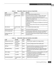
...the drive is powered up delay of a slot. Flashing (at a constant rate) when the disk drive is not obvious from the Back of the IP4700. if the fault is spinning up but not handling any fault condition exists; This LED stays active until the SPS completes a successful power test. Table...with fan pack cover on the front, look at the back of the IP4700 Light Quantity Color Meaning Storage processor active 1 per link control Green card On when the LCC is powered up or spinning down normally. SPS replace battery 1 per disk module Green slot Off when the module slot is...
...the drive is powered up delay of a slot. Flashing (at a constant rate) when the disk drive is not obvious from the Back of the IP4700. if the fault is spinning up but not handling any fault condition exists; This LED stays active until the SPS completes a successful power test. Table...with fan pack cover on the front, look at the back of the IP4700 Light Quantity Color Meaning Storage processor active 1 per link control Green card On when the LCC is powered up or spinning down normally. SPS replace battery 1 per disk module Green slot Off when the module slot is...
Service Guide
Page 64
... link is active and NIC is on the NIC. Cooling fault 1 per SP Amber With solid Link LED, indicates data activity on , you replace the faulty CRU. 3-4 IP4700 Installation and Service Guide LAN data (gigabit) 1 per supply Amber Flashing when multiple fans in the drive fan pack is faulty. Power supply active...
... link is active and NIC is on the NIC. Cooling fault 1 per SP Amber With solid Link LED, indicates data activity on , you replace the faulty CRU. 3-4 IP4700 Installation and Service Guide LAN data (gigabit) 1 per supply Amber Flashing when multiple fans in the drive fan pack is faulty. Power supply active...

Service Guide
Page 65
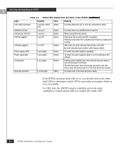
...processor will affect performance and may temporarily impair operating system access to ensure EMI compliance and proper air flow over the CRUs. While the IP4700 is powered up. Doing so effectively bypasses the SPS, and write cache data cannot be powered up when you can remove the drive fan... pack or storage processor fan pack while the IP4700 is powered up, you reinstall the drive or storage processor fan pack. Its CRUs are hot swappable. Cache Dirty) 0 0xafb40 0x14362c. NOTE: You can service or replace any CRU. Do not remove a faulty CRU until you must ...
...processor will affect performance and may temporarily impair operating system access to ensure EMI compliance and proper air flow over the CRUs. While the IP4700 is powered up. Doing so effectively bypasses the SPS, and write cache data cannot be powered up when you can remove the drive fan... pack or storage processor fan pack while the IP4700 is powered up, you reinstall the drive or storage processor fan pack. Its CRUs are hot swappable. Cache Dirty) 0 0xafb40 0x14362c. NOTE: You can service or replace any CRU. Do not remove a faulty CRU until you must ...

Service Guide
Page 66
...can inadvertently damage the sensitive electronic circuits in the work on each SPS 4. Shut off (0) position. Servicing and Upgrading an IP4700 3 3. Remove the drive fan pack (see Replacing the Drive Fan Pack on page 3-20.), and set the power switch on the equipment. Avoiding Electrostatic Discharge (ESD) ...you may build up electrostatic charge, such as foam packaging, foam cups, cellophane wrappers, and similar items. • Do not remove replacement or upgrade CRUs from the work site of an electrostatic discharge by touching them . • Gather together the ESD kit and all ...
...can inadvertently damage the sensitive electronic circuits in the work on each SPS 4. Shut off (0) position. Servicing and Upgrading an IP4700 3 3. Remove the drive fan pack (see Replacing the Drive Fan Pack on page 3-20.), and set the power switch on the equipment. Avoiding Electrostatic Discharge (ESD) ...you may build up electrostatic charge, such as foam packaging, foam cups, cellophane wrappers, and similar items. • Do not remove replacement or upgrade CRUs from the work site of an electrostatic discharge by touching them . • Gather together the ESD kit and all ...

Service Guide
Page 67
... CRUs. • Do not remove a faulty CRU until you are not a substitute for repair. • Maintain the location where you have a replacement available. • Handle a CRU only when using an ESD wristband as follows: Attach the clip of an ESD kit. When you have installed the... the room or contact other surfaces before installing a CRU, first place the CRU back in Appendix A. Handling CRUs 3-7 Servicing and Upgrading an IP4700 3 IMPORTANT: These procedures are ready again to install the CRU, repeat these procedures. Once you store CRUs within the limits specified in the...
... CRUs. • Do not remove a faulty CRU until you are not a substitute for repair. • Maintain the location where you have a replacement available. • Handle a CRU only when using an ESD wristband as follows: Attach the clip of an ESD kit. When you have installed the... the room or contact other surfaces before installing a CRU, first place the CRU back in Appendix A. Handling CRUs 3-7 Servicing and Upgrading an IP4700 3 IMPORTANT: These procedures are ready again to install the CRU, repeat these procedures. Once you store CRUs within the limits specified in the...

Service Guide
Page 68
... may damage a disk module being inserted or removed. • Handle a disk module gently and use an ESD wristband. Servicing and Upgrading an IP4700 3 Replacing or Adding a Disk Module ! When replacing or adding a disk module, observe the following: • Remove or install disk modules only while the storage system is required for periods when...
... may damage a disk module being inserted or removed. • Handle a disk module gently and use an ESD wristband. Servicing and Upgrading an IP4700 3 Replacing or Adding a Disk Module ! When replacing or adding a disk module, observe the following: • Remove or install disk modules only while the storage system is required for periods when...

Service Guide
Page 69
To replace a disk module: 1. Front door Keylock Figure 3-2 Unlocking the Front Door EMC1445 Replacing or Adding a Disk Module 3-9 Unlock and open the IP4700's front door to access the disk modules. The door must open the front door as a spare, contact your service provider for EMI compliance when the IP4700 is powered up. CAUTION You must be closed for assistance. ! Open it only to use a previously used disk module as shown in Figures 3-2 and 3-3. Servicing and Upgrading an IP4700 3 IMPORTANT: If you want to replace or add a disk module.
To replace a disk module: 1. Front door Keylock Figure 3-2 Unlocking the Front Door EMC1445 Replacing or Adding a Disk Module 3-9 Unlock and open the IP4700's front door to access the disk modules. The door must open the front door as a spare, contact your service provider for EMI compliance when the IP4700 is powered up. CAUTION You must be closed for assistance. ! Open it only to use a previously used disk module as shown in Figures 3-2 and 3-3. Servicing and Upgrading an IP4700 3 IMPORTANT: If you want to replace or add a disk module.

Service Guide
Page 70
...See Figure 3-4. If the active LED is off, you want to install the replacement disk module. 3. NOTE: If the active LED is on the latch. 4. then remove the disk module from the slot. 3-10 IP4700 Installation and Service Guide Press the latch and slowly pull the module from the ...slot. Wait 30 seconds for the disk to stop spinning. Servicing and Upgrading an IP4700 3 EMC1446 Figure 3-3 Opening the Front Door 2. Locate the slot...
...See Figure 3-4. If the active LED is off, you want to install the replacement disk module. 3. NOTE: If the active LED is on the latch. 4. then remove the disk module from the slot. 3-10 IP4700 Installation and Service Guide Press the latch and slowly pull the module from the ...slot. Wait 30 seconds for the disk to stop spinning. Servicing and Upgrading an IP4700 3 EMC1446 Figure 3-3 Opening the Front Door 2. Locate the slot...

Service Guide
Page 71
... 3-2). Remove and store the ESD wristband. Grasp the disk module handle, and align the module with the guides in the slot. 2. Replacing or Adding a Disk Module 3-11 Servicing and Upgrading an IP4700 3 Figure 3-4 Removing a Disk Module EMC1447 IMPORTANT: After removing a disk module, wait for the activity lights on the other drives to...
... 3-2). Remove and store the ESD wristband. Grasp the disk module handle, and align the module with the guides in the slot. 2. Replacing or Adding a Disk Module 3-11 Servicing and Upgrading an IP4700 3 Figure 3-4 Removing a Disk Module EMC1447 IMPORTANT: After removing a disk module, wait for the activity lights on the other drives to...


