
Service Guide
Page 5
... xiii Chapter 1 The IP4700 About the IP4700 1-2 IP4700 Components 1-4 Customer-Replaceable Units (CRUs 1-4 High-Availability Features 1-5 Enclosure 1-6 Front Panel 1-7 Front Door 1-9 Midplane 1-9 Storage Processors 1-10 Link Control Cards (LCCs 1-12 Disk Modules 1-13 Disk Drives 1-13 Drive Carrier 1-13 Power Supplies 1-14 SPS (Standby Power Supply 1-16 Drive Fan Pack 1-17 Storage Processor Fan Pack 1-18 Chapter 2 Installing an IP4700 Requirements 2-2 Site Requirements 2-2 Cabling Requirements 2-2 Addressing Requirements 2-6 IP4700 Installation and Service Guide v
... xiii Chapter 1 The IP4700 About the IP4700 1-2 IP4700 Components 1-4 Customer-Replaceable Units (CRUs 1-4 High-Availability Features 1-5 Enclosure 1-6 Front Panel 1-7 Front Door 1-9 Midplane 1-9 Storage Processors 1-10 Link Control Cards (LCCs 1-12 Disk Modules 1-13 Disk Drives 1-13 Drive Carrier 1-13 Power Supplies 1-14 SPS (Standby Power Supply 1-16 Drive Fan Pack 1-17 Storage Processor Fan Pack 1-18 Chapter 2 Installing an IP4700 Requirements 2-2 Site Requirements 2-2 Cabling Requirements 2-2 Addressing Requirements 2-6 IP4700 Installation and Service Guide v
Service Guide
Page 6
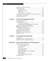
...2-9 LAN Connectors 2-9 Management Console 2-12 SCSI Cable 2-12 Link Control Card Connectors 2-14 Attaching the Power Cords and Powering Up the IP4700 .......2-16 Powering Down the IP4700 2-21 Abnormal Powerdown 2-23 Chapter 3 Servicing and Upgrading an IP4700 Monitoring IP4700 Status 3-2 Handling CRUs 3-5 Power Issues and CRUs 3-5 Avoiding Electrostatic Discharge (ESD) Damage 3-6 Replacing or Adding a Disk Module 3-8 Replacing the Storage Processor Fan Pack 3-13 Replacing a Storage Processor 3-15 Installing a Storage Processor 3-16 Replacing a Link Control Card 3-17 Replacing...
...2-9 LAN Connectors 2-9 Management Console 2-12 SCSI Cable 2-12 Link Control Card Connectors 2-14 Attaching the Power Cords and Powering Up the IP4700 .......2-16 Powering Down the IP4700 2-21 Abnormal Powerdown 2-23 Chapter 3 Servicing and Upgrading an IP4700 Monitoring IP4700 Status 3-2 Handling CRUs 3-5 Power Issues and CRUs 3-5 Avoiding Electrostatic Discharge (ESD) Damage 3-6 Replacing or Adding a Disk Module 3-8 Replacing the Storage Processor Fan Pack 3-13 Replacing a Storage Processor 3-15 Installing a Storage Processor 3-16 Replacing a Link Control Card 3-17 Replacing...

Service Guide
Page 9
... • install an IP4700 • upgrade an IP4700 by adding disk modules and disk-array enclosures (DAEs) • replace failed CRUs • install, service, and use the DC Standby Power Supply (DC SPS) IP4700 Installation and Service Guide ix Preface This manual explains how to install the IP4700, install or replace the Standby Power Supply (SPS), and how to install the IP4700 in a rackmount cabinet already on site, we assume that you have installed the appropriate mounting tray and rails as...
... • install an IP4700 • upgrade an IP4700 by adding disk modules and disk-array enclosures (DAEs) • replace failed CRUs • install, service, and use the DC Standby Power Supply (DC SPS) IP4700 Installation and Service Guide ix Preface This manual explains how to install the IP4700, install or replace the Standby Power Supply (SPS), and how to install the IP4700 in a rackmount cabinet already on site, we assume that you have installed the appropriate mounting tray and rails as...

Service Guide
Page 10
... ignore the warning. Glossary defines terms used in this manual: Chapter 1 introduces the IP4700's components. x IP4700 Installation and Service Guide Appendix A lists the IP4700 and SPS technical specifications. Chapter 2 explains requirements and describes how to install the IP4700 and cable it explains how to Disk Array Enclosures (DAEs). The caution may apply to them. Chapter 4 introduces the Standby Power Supply (SPS) and explains how to install and connect cables to hardware or software. Chapter 3 describes...
... ignore the warning. Glossary defines terms used in this manual: Chapter 1 introduces the IP4700's components. x IP4700 Installation and Service Guide Appendix A lists the IP4700 and SPS technical specifications. Chapter 2 explains requirements and describes how to install the IP4700 and cable it explains how to Disk Array Enclosures (DAEs). The caution may apply to them. Chapter 4 introduces the Standby Power Supply (SPS) and explains how to install and connect cables to hardware or software. Chapter 3 describes...

Service Guide
Page 22
... processors (SPs) • Two link control cards (LCCs) • Ten disk drive modules • Two power supplies • One drive fan pack • One storage processor fan pack • Two standby power supplies (SPSs) Customer-Replaceable Units (CRUs) The following are customer-replaceable units (CRUs), which you can add or replace without tools while the IP4700 is powered up: • Storage processors • Link control cards • Disk modules • Power supplies • Fan packs • Filler modules • Standby power supplies 1-4 IP4700 Installation and Service Guide
... processors (SPs) • Two link control cards (LCCs) • Ten disk drive modules • Two power supplies • One drive fan pack • One storage processor fan pack • Two standby power supplies (SPSs) Customer-Replaceable Units (CRUs) The following are customer-replaceable units (CRUs), which you can add or replace without tools while the IP4700 is powered up: • Storage processors • Link control cards • Disk modules • Power supplies • Fan packs • Filler modules • Standby power supplies 1-4 IP4700 Installation and Service Guide

Service Guide
Page 23
... disk drives • Two SPSs (standby power supplies) with fully charged batteries The second storage processor provides continued access to your data despite the failure of data from a failed path to a working one supply fail. The SPSs provide power for an IP4700 are FC-AL compliant and support dual-port FC-AL interconnects through the two link control cards and their cabling. Either autonomous, auto-ranging power supply can eliminate downtime and make some problem recovery...
... disk drives • Two SPSs (standby power supplies) with fully charged batteries The second storage processor provides continued access to your data despite the failure of data from a failed path to a working one supply fail. The SPSs provide power for an IP4700 are FC-AL compliant and support dual-port FC-AL interconnects through the two link control cards and their cabling. Either autonomous, auto-ranging power supply can eliminate downtime and make some problem recovery...

Service Guide
Page 30
..., disks, and other enclosures • Bypass capability for faulted or missing units • Monitor and control of the enclosure elements Active LED (green) Expansion FC-AL cable connector (EXP) Fault LED (amber) EMC1458 Figure 1-8 Link Control Card Each link control card independently monitors the environmental status of the entire IP4700, using special protocols. The IP4700 1 Link Control Cards (LCCs) A link control card (see the Monitoring IP4700 Status section in Chapter 3. These protocols let the storage processor poll IP4700 status and send commands that is powered up...
..., disks, and other enclosures • Bypass capability for faulted or missing units • Monitor and control of the enclosure elements Active LED (green) Expansion FC-AL cable connector (EXP) Fault LED (amber) EMC1458 Figure 1-8 Link Control Card Each link control card independently monitors the environmental status of the entire IP4700, using special protocols. The IP4700 1 Link Control Cards (LCCs) A link control card (see the Monitoring IP4700 Status section in Chapter 3. These protocols let the storage processor poll IP4700 status and send commands that is powered up...

Service Guide
Page 32
... faults will not adversely affect the operation of any other fails. You can support a fully configured IP4700 if the other CRU. A CRU with the drive fan pack 1-14 IP4700 Installation and Service Guide Power supply A Power supply B EMC1469 Figure 1-10 Power Supplies Each power supply is powered up . The disk drive and link control card voltage lines have individual soft-start switches that protect them if you install them while the IP4700 is powered up . Each power supply has status LEDs. each supply can add or remove one fails; The IP4700 1 Power Supplies...
... faults will not adversely affect the operation of any other fails. You can support a fully configured IP4700 if the other CRU. A CRU with the drive fan pack 1-14 IP4700 Installation and Service Guide Power supply A Power supply B EMC1469 Figure 1-10 Power Supplies Each power supply is powered up . The disk drive and link control card voltage lines have individual soft-start switches that protect them if you install them while the IP4700 is powered up . Each power supply has status LEDs. each supply can add or remove one fails; The IP4700 1 Power Supplies...

Service Guide
Page 35
... power supplies. Drive Fan Pack 1-17 While the fan is removed, the cache is removed, the Cooling Check LED on the drive fan pack hold the pack in higher acoustic noise. A separate pack (described in the IP4700. The drive fan pack has one status light. While the pack is off and flushing; The disk modules and storage processors power up . Figure 1-13 Drive Fan Pack Fan fault LED (yellow) EMC1451 IMPORTANT: You can power it. If a fan fails, the voltage...
... power supplies. Drive Fan Pack 1-17 While the fan is removed, the cache is removed, the Cooling Check LED on the drive fan pack hold the pack in higher acoustic noise. A separate pack (described in the IP4700. The drive fan pack has one status light. While the pack is off and flushing; The disk modules and storage processors power up . Figure 1-13 Drive Fan Pack Fan fault LED (yellow) EMC1451 IMPORTANT: You can power it. If a fan fails, the voltage...

Service Guide
Page 36
... removed for more than approximately two minutes, the SPs and disk modules power down. If a fan fails, the voltage and speed of the IP4700. Fault LED (amber) Latches Figure 1-14 Storage Processor Fan Pack EMC1470 IMPORTANT: You can power it. It contains three fans that draw ambient room air through the storage processor fan pack cover, through the midplane, and across the storage processors. The fans operate at a lower voltage and speed during normal operation to install a IP4700. 1-18 IP4700 Installation and Service Guide...
... removed for more than approximately two minutes, the SPs and disk modules power down. If a fan fails, the voltage and speed of the IP4700. Fault LED (amber) Latches Figure 1-14 Storage Processor Fan Pack EMC1470 IMPORTANT: You can power it. It contains three fans that draw ambient room air through the storage processor fan pack cover, through the midplane, and across the storage processors. The fans operate at a lower voltage and speed during normal operation to install a IP4700. 1-18 IP4700 Installation and Service Guide...

Service Guide
Page 43
.... your configuration may differ. Installing an IP4700 in einem Gehäuse cabinet anti-tip devices, especially if you will need to refer to provide reliable grounding. Installing an IP4700 2 Installing an IP4700 in a Cabinet The cabinet in which the IP4700 is installed must have its own switchable, dual power distribution units, one on two L-shaped mounting rails connected to lift and install the IP4700 into a rack by...
.... your configuration may differ. Installing an IP4700 in einem Gehäuse cabinet anti-tip devices, especially if you will need to refer to provide reliable grounding. Installing an IP4700 2 Installing an IP4700 in a Cabinet The cabinet in which the IP4700 is installed must have its own switchable, dual power distribution units, one on two L-shaped mounting rails connected to lift and install the IP4700 into a rack by...
Service Guide
Page 49
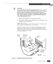
... not connect it directly to -LVD connections require an intermediary signal converter. HVD-to the LVD adapter in the IP4700 storage processor. CAUTION If your tape device(s) by clicking Tape Drives in the SCSI path, connect one storage processor to your NDMP backup software documentation for further configuration instructions. Refer to each connector on the cable's connectors. 5. After the next system boot, you can verify that the IP4700 has scanned the SCSI buses...
... not connect it directly to -LVD connections require an intermediary signal converter. HVD-to the LVD adapter in the IP4700 storage processor. CAUTION If your tape device(s) by clicking Tape Drives in the SCSI path, connect one storage processor to your NDMP backup software documentation for further configuration instructions. Refer to each connector on the cable's connectors. 5. After the next system boot, you can verify that the IP4700 has scanned the SCSI buses...

Service Guide
Page 62
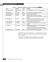
... storage processor fan pack is on with the fan pack cover in Figure 3-5, to examine the storage processor fan pack fault LED. If the IP4700 system fault LED is not visible with no other fault LED on, remove the fan pack cover, as shown in place. Enclosure addresses 0 02 4 13 5 # 1 6 8 10 7 9 11 # 2 Disk drive fault LED (amber) 3 4 5 Disk drive Disk drive number active LED (green) Enclosure fault LED (amber) 6 7 8 9 Enclosure power LED (green) Figure 3-1 Status LEDs Visible from the back. Figure 3-1, Table 3-1, and Table 3-2 describe the status LEDs. Some LEDs...
... storage processor fan pack is on with the fan pack cover in Figure 3-5, to examine the storage processor fan pack fault LED. If the IP4700 system fault LED is not visible with no other fault LED on, remove the fan pack cover, as shown in place. Enclosure addresses 0 02 4 13 5 # 1 6 8 10 7 9 11 # 2 Disk drive fault LED (amber) 3 4 5 Disk drive Disk drive number active LED (green) Enclosure fault LED (amber) 6 7 8 9 Enclosure power LED (green) Figure 3-1 Status LEDs Visible from the back. Figure 3-1, Table 3-1, and Table 3-2 describe the status LEDs. Some LEDs...
Service Guide
Page 64
...-AL connection is faulty. If the IP4700 enclosure fault LED is on, you replace the faulty CRU. 3-4 IP4700 Installation and Service Guide Drive fan pack fault 1 on the NIC. Servicing and Upgrading an IP4700 3 Table 3-2 Status LEDs Visible from the Back of the IP4700 (continued) Light Quantity Color Meaning Link control card fault 1 per supply Amber Flashing when multiple fans in the drive fan pack is loaded and running. LAN activity (10/100) 1 per SP Amber With solid Link LED, indicates data activity on fan pack Yellow...
...-AL connection is faulty. If the IP4700 enclosure fault LED is on, you replace the faulty CRU. 3-4 IP4700 Installation and Service Guide Drive fan pack fault 1 on the NIC. Servicing and Upgrading an IP4700 3 Table 3-2 Status LEDs Visible from the Back of the IP4700 (continued) Light Quantity Color Meaning Link control card fault 1 per supply Amber Flashing when multiple fans in the drive fan pack is loaded and running. LAN activity (10/100) 1 per SP Amber With solid Link LED, indicates data activity on fan pack Yellow...

Service Guide
Page 65
... unsolicited event log displays an error message similar to: Enclosure 0 Disk 5 0x90a (Can't Assign - The IP4700 is designed to the IP4700 Handling CRUs 3-5 However, removing an active link control card or storage processor will affect performance and may temporarily impair operating system access to shut down the storage processors (see Chapter 8 in the IP4700 Administrator's Guide). 2. If the pack is powered up. Doing so effectively bypasses the SPS, and write cache data...
... unsolicited event log displays an error message similar to: Enclosure 0 Disk 5 0x90a (Can't Assign - The IP4700 is designed to the IP4700 Handling CRUs 3-5 However, removing an active link control card or storage processor will affect performance and may temporarily impair operating system access to shut down the storage processors (see Chapter 8 in the IP4700 Administrator's Guide). 2. If the pack is powered up. Doing so effectively bypasses the SPS, and write cache data...

Service Guide
Page 83
CAUTION To access a power supply module, you have a replacement supply or filler module available. If the wrong power supply is removed for more than 2 minutes, the storage processors and disk modules power down . If you are removing the top power supply, push the latch up and to correctly identify the correct power supply - Grasp the power supply handle with the same type of power supply (as shown in the power supply section of Chapter 1). Handle a power supply gently, and use an...
CAUTION To access a power supply module, you have a replacement supply or filler module available. If the wrong power supply is removed for more than 2 minutes, the storage processors and disk modules power down . If you are removing the top power supply, push the latch up and to correctly identify the correct power supply - Grasp the power supply handle with the same type of power supply (as shown in the power supply section of Chapter 1). Handle a power supply gently, and use an...

Service Guide
Page 119
... (standby power supply) In the context of a disk-array storage system, the procedure by which you format one or more disk modules into one of several types of a device's heat output. DAE (Disk Array Enclosure) disk drive module D A storage device that anyone can install or replace. Another name for disk module. IP4700 Installation and Service Guide g-1 Glossary The terms defined here are important to 10 disk modules, one or two Fibre Channel link control cards, and one or two power supplies. A hardware component...
... (standby power supply) In the context of a disk-array storage system, the procedure by which you format one or more disk modules into one of several types of a device's heat output. DAE (Disk Array Enclosure) disk drive module D A storage device that anyone can install or replace. Another name for disk module. IP4700 Installation and Service Guide g-1 Glossary The terms defined here are important to 10 disk modules, one or two Fibre Channel link control cards, and one or two power supplies. A hardware component...
Service Guide
Page 123
... adding disk module 3-8 link control card (LCC) 3-17 power supply 3-23 storage processor (SP) 3-16 addressing requirements 2-6 avoiding electrostatic discharge (ESD) damage 3-6 B battery pack charge times A-8 lifetime 4-4 part number 4-12 self-discharge times A-10, A-11 SPS, replacing in rackmount system 4-12 tests A-10 C cabinet requirements 2-7 cable pinout information A-11 cables, copper removing from link control card 3-17 specifications, for link control card A-3 requirements 2-2 carrier, drive 1-13 charge time, battery pack A-8 circuit breaker 4-2 configurations 1-18 cooling fault LED...
... adding disk module 3-8 link control card (LCC) 3-17 power supply 3-23 storage processor (SP) 3-16 addressing requirements 2-6 avoiding electrostatic discharge (ESD) damage 3-6 B battery pack charge times A-8 lifetime 4-4 part number 4-12 self-discharge times A-10, A-11 SPS, replacing in rackmount system 4-12 tests A-10 C cabinet requirements 2-7 cable pinout information A-11 cables, copper removing from link control card 3-17 specifications, for link control card A-3 requirements 2-2 carrier, drive 1-13 charge time, battery pack A-8 circuit breaker 4-2 configurations 1-18 cooling fault LED...

Service Guide
Page 125
... fan pack fault 3-3 storage processor fan pack fault 3-3 status lights 1-8 storage processor fan pack description 1-17 replacing 3-13 technical specifications A-2 weight A-3 width A-3 Index J JBOD (just a box of disks), See DAE (Disk-Array Enclosure) L LEDs IP4700 status 3-2 link control card (LCC) 3-19 length restrictions, copper cabling A-3 link control card (LCC) adding 3-17 cabling requirements 2-2 cabling specifications A-3 description 1-12 fault LED 3-3 installing 3-19 lights 1-12 removing copper cables from 3-17 replacing 3-17 loose cable 2-5 M midplane description 1-9 N non-operating...
... fan pack fault 3-3 storage processor fan pack fault 3-3 status lights 1-8 storage processor fan pack description 1-17 replacing 3-13 technical specifications A-2 weight A-3 width A-3 Index J JBOD (just a box of disks), See DAE (Disk-Array Enclosure) L LEDs IP4700 status 3-2 link control card (LCC) 3-19 length restrictions, copper cabling A-3 link control card (LCC) adding 3-17 cabling requirements 2-2 cabling specifications A-3 description 1-12 fault LED 3-3 installing 3-19 lights 1-12 removing copper cables from 3-17 replacing 3-17 loose cable 2-5 M midplane description 1-9 N non-operating...

Service Guide
Page 126
... 3-5 R removing copper cables from link control card 3-17 drive fan pack 2-16, 3-20 power supply 3-23 replacing disk module 3-8 drive fan pack 3-20 link control card (LCC) 3-17 power supply 3-23 storage processor (SP) 3-16 storage processor fan pack 3-23 S service clearance A-9 SFF-8067 standard 1-13 shipping requirements A-7 site requirements 2-2, A-2 size, IP4700 A-3 size, SPS (standby power supply) A-9 snap fingers 4-10, 4-18 specification, IP4700 A-2 SPS (standby power supply) 1-16 about 4-2 back panel 4-2 battery pack, replacing in rackmount system 4-12 defined 4 dimensions A-9 fault LEDs...
... 3-5 R removing copper cables from link control card 3-17 drive fan pack 2-16, 3-20 power supply 3-23 replacing disk module 3-8 drive fan pack 3-20 link control card (LCC) 3-17 power supply 3-23 storage processor (SP) 3-16 storage processor fan pack 3-23 S service clearance A-9 SFF-8067 standard 1-13 shipping requirements A-7 site requirements 2-2, A-2 size, IP4700 A-3 size, SPS (standby power supply) A-9 snap fingers 4-10, 4-18 specification, IP4700 A-2 SPS (standby power supply) 1-16 about 4-2 back panel 4-2 battery pack, replacing in rackmount system 4-12 defined 4 dimensions A-9 fault LEDs...

