
User Guide
Page 19
... personal safety. Before Working Inside Your Computer Use the following tools: • Small flat-blade screwdriver • Phillips screwdriver • Flash BIOS update program floppy disk or CD Turning Off Your Computer NOTICE: To avoid losing data, save and close any open files, exit any open... programs, click the Start button, and then click Turn Off Computer. b In the Turn off computer window, click Turn off your computer. 1 Shut down your Dell™ Product Information Guide. • A component can be replaced by its metal mounting bracket. If your computer and ...
... personal safety. Before Working Inside Your Computer Use the following tools: • Small flat-blade screwdriver • Phillips screwdriver • Flash BIOS update program floppy disk or CD Turning Off Your Computer NOTICE: To avoid losing data, save and close any open files, exit any open... programs, click the Start button, and then click Turn Off Computer. b In the Turn off computer window, click Turn off your computer. 1 Shut down your Dell™ Product Information Guide. • A component can be replaced by its metal mounting bracket. If your computer and ...
User Guide
Page 35
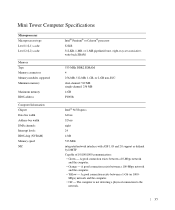
... type Level 1 (L1) cache Level 2 (L2) cache Memory Type Memory connectors Memory modules supported Minimum memory Maximum memory BIOS address Computer Information Chipset Data bus width Address bus width DMA channels Interrupt levels BIOS chip (NVRAM) Memory speed NIC Intel® Pentium® or Celeron® processor 32 KB 512-KB, 1-MB...
... type Level 1 (L1) cache Level 2 (L2) cache Memory Type Memory connectors Memory modules supported Minimum memory Maximum memory BIOS address Computer Information Chipset Data bus width Address bus width DMA channels Interrupt levels BIOS chip (NVRAM) Memory speed NIC Intel® Pentium® or Celeron® processor 32 KB 512-KB, 1-MB...

User Guide
Page 105
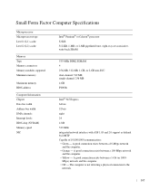
... between a 10-Mbps network and the computer. • Orange - Mbps) network and the computer. • Off - Desktop Computer Specifications Microprocessor Microprocessor type Level 1 (L1) cache Level 2 (L2) cache Memory Type Memory connectors Memory modules supported Minimum memory Maximum memory... BIOS address Computer Information Chipset Data bus width Address bus width DMA channels Interrupt levels BIOS chip (NVRAM) Memory speed NIC Intel® Pentium® or Celeron® processor...
... between a 10-Mbps network and the computer. • Orange - Mbps) network and the computer. • Off - Desktop Computer Specifications Microprocessor Microprocessor type Level 1 (L1) cache Level 2 (L2) cache Memory Type Memory connectors Memory modules supported Minimum memory Maximum memory... BIOS address Computer Information Chipset Data bus width Address bus width DMA channels Interrupt levels BIOS chip (NVRAM) Memory speed NIC Intel® Pentium® or Celeron® processor...
User Guide
Page 165
... type Level 1 (L1) cache Level 2 (L2) cache Memory Type Memory connectors Memory modules supported Minimum memory Maximum memory BIOS address Computer Information Chipset Data bus width Address bus width DMA channels Interrupt levels BIOS chip (NVRAM) Memory speed NIC Intel® Pentium® or Celeron® processor 32 KB 512-KB, 1-MB...
... type Level 1 (L1) cache Level 2 (L2) cache Memory Type Memory connectors Memory modules supported Minimum memory Maximum memory BIOS address Computer Information Chipset Data bus width Address bus width DMA channels Interrupt levels BIOS chip (NVRAM) Memory speed NIC Intel® Pentium® or Celeron® processor 32 KB 512-KB, 1-MB...
User Guide
Page 213
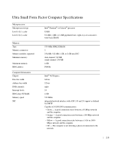
... type Level 1 (L1) cache Level 2 (L2) cache Memory Type Memory connectors Memory modules supported Minimum memory Maximum memory BIOS address Computer Information Chipset Data bus width Address bus width DMA channels Interrupt levels BIOS chip (NVRAM) Memory speed NIC Intel® Pentium® or Celeron® processor 32 KB 512-KB, 1-MB...
... type Level 1 (L1) cache Level 2 (L2) cache Memory Type Memory connectors Memory modules supported Minimum memory Maximum memory BIOS address Computer Information Chipset Data bus width Address bus width DMA channels Interrupt levels BIOS chip (NVRAM) Memory speed NIC Intel® Pentium® or Celeron® processor 32 KB 512-KB, 1-MB...

User Guide
Page 240
... For more information about Dell's ASF implementation, see the ASF User's Guide and the ASF Administrator's Guide, which is based on DMI and CIM, is available for your computer, such as updating its BIOS or shutting it is running. • Monitor the status of your computer, ...such as listening for thermal alerts from temperature probes or hard-drive failure alerts from storage devices. • Change the state of your computer. For information about Dell OpenManage Client Instrumentation, see the Dell ...
... For more information about Dell's ASF implementation, see the ASF User's Guide and the ASF Administrator's Guide, which is based on DMI and CIM, is available for your computer, such as updating its BIOS or shutting it is running. • Monitor the status of your computer, ...such as listening for thermal alerts from temperature probes or hard-drive failure alerts from storage devices. • Change the state of your computer. For information about Dell OpenManage Client Instrumentation, see the Dell ...
User Guide
Page 247
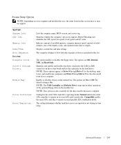
...mode. Advanced Features 247 System System Info CPU Info Memory Info Date/Time Boot Sequence Drives Diskette Drive Drive 0 through Drive 3 for the desktop, mini tower, and small form computers and Drive 0 though Drive 5 for the ultra small form factor computer. This option enables or disables ... ATA combination mode. NOTE: These options appear as Drive 0 through Drive n Module Bay Drive Controller Error Reporting Lists the computer name, BIOS version, and service tag. The options are reported or not during system setup. NOTE: The USB Controller and Diskette Drive setup option affect...
...mode. Advanced Features 247 System System Info CPU Info Memory Info Date/Time Boot Sequence Drives Diskette Drive Drive 0 through Drive 3 for the desktop, mini tower, and small form computers and Drive 0 though Drive 5 for the ultra small form factor computer. This option enables or disables ... ATA combination mode. NOTE: These options appear as Drive 0 through Drive n Module Bay Drive Controller Error Reporting Lists the computer name, BIOS version, and service tag. The options are reported or not during system setup. NOTE: The USB Controller and Diskette Drive setup option affect...

User Guide
Page 249
... image. port is disabled On - NOTE: Switching to performance mode may cause the drive to video controllers. The USB controller is disabled AT - however, the BIOS will not recognize USB storage devices. Enabled The factory default setting is enabled; Your computer does not test or change the current acoustics mode setting...
... image. port is disabled On - NOTE: Switching to performance mode may cause the drive to video controllers. The USB controller is disabled AT - however, the BIOS will not recognize USB storage devices. Enabled The factory default setting is enabled; Your computer does not test or change the current acoustics mode setting...

User Guide
Page 251
... is Off. Suspend Mode The options are S1, a suspend mode where the computer is running in both the date and time fields. BIOS Update Select the location of week to automatically turn on the computer. The factory default setting is reduced or turned off your computer using ...or Hard Drive. however, system memory remains active. The options are Everyday or Weekdays. Auto Power On Sets time and days of the BIOS update file. TPM Security Controls the TPM security device. Intrusion Status This option appears in conjunction with the Auto Power On setting. The factory...
... is Off. Suspend Mode The options are S1, a suspend mode where the computer is running in both the date and time fields. BIOS Update Select the location of week to automatically turn on the computer. The factory default setting is reduced or turned off your computer using ...or Hard Drive. however, system memory remains active. The options are Everyday or Weekdays. Auto Power On Sets time and days of the BIOS update file. TPM Security Controls the TPM security device. Intrusion Status This option appears in conjunction with the Auto Power On setting. The factory...

User Guide
Page 253
... the USB floppy drive, insert a bootable floppy, and re-boot the system. For example, if you are booting to wait until you see the Microsoft Windows desktop. To ensure that is to it . 3 Press the up- If you wait too long and the operating system logo appears, continue to a USB memory key... be bootable. NOTE: To boot to move through the list of the screen, press . and down your device is bootable, check the device documentation. The BIOS detects the device and adds the USB device option to the boot menu. 3 From the boot menu, select the number that appears next to the...
... the USB floppy drive, insert a bootable floppy, and re-boot the system. For example, if you are booting to wait until you see the Microsoft Windows desktop. To ensure that is to it . 3 Press the up- If you wait too long and the operating system logo appears, continue to a USB memory key... be bootable. NOTE: To boot to move through the list of the screen, press . and down your device is bootable, check the device documentation. The BIOS detects the device and adds the USB device option to the boot menu. 3 From the boot menu, select the number that appears next to the...
User Guide
Page 267
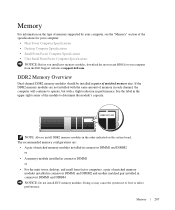
... by your computer, see the "Memory" section of the specifications for your computer: • Mini Tower Computer Specifications • Desktop Computer Specifications • Small Form Factor Computer Specifications • Ultra Small Form Factor Computer Specifications NOTICE: Before you install new memory... modules, download the most recent BIOS for your computer from the Dell Support website at support.dell.com. If the DDR2 memory modules are : • A pair of matched memory modules installed in...
... by your computer, see the "Memory" section of the specifications for your computer: • Mini Tower Computer Specifications • Desktop Computer Specifications • Small Form Factor Computer Specifications • Ultra Small Form Factor Computer Specifications NOTICE: Before you install new memory... modules, download the most recent BIOS for your computer from the Dell Support website at support.dell.com. If the DDR2 memory modules are : • A pair of matched memory modules installed in...

User Guide
Page 269
... on the desktop computer requires you begin any new modules that require address space. You should install your computer warranty. 1 Follow the procedures in connectors DIMM1 and DIMM2 or connectors DIMM3 and DIMM4. The BIOS then subtracts the reserved address space from Dell. If possible... modules in pairs either in "Before You Begin." 2 Carefully press out the securing clip at each end of reserved address space required. The BIOS dynamically calculates the amount of the memory module connector. 1 2 1 memory module 2 securing clip (2) 3 Remove the memory module. Memory 269...
... on the desktop computer requires you begin any new modules that require address space. You should install your computer warranty. 1 Follow the procedures in connectors DIMM1 and DIMM2 or connectors DIMM3 and DIMM4. The BIOS then subtracts the reserved address space from Dell. If possible... modules in pairs either in "Before You Begin." 2 Carefully press out the securing clip at each end of reserved address space required. The BIOS dynamically calculates the amount of the memory module connector. 1 2 1 memory module 2 securing clip (2) 3 Remove the memory module. Memory 269...
User Guide
Page 309
...array of RAID include RAID 0, RAID 1, RAID 5, RAID 10, and RAID 50. A text file included with existing hardware if the BIOS, operating system, and all devices are Plug and Play compliant. Typically, readme files provide installation information and describe new product enhancements or ... 800 x 600, is lost when you can have an operating system to create an image. PI X E L - POS T - A type of Glossary 309 Any information stored in RAM is expressed as part of 10 kHz to specific individuals. O N L Y - R E S O L U T I L E - read -only status if: • It...
...array of RAID include RAID 0, RAID 1, RAID 5, RAID 10, and RAID 50. A text file included with existing hardware if the BIOS, operating system, and all devices are Plug and Play compliant. Typically, readme files provide installation information and describe new product enhancements or ... 800 x 600, is lost when you can have an operating system to create an image. PI X E L - POS T - A type of Glossary 309 Any information stored in RAM is expressed as part of 10 kHz to specific individuals. O N L Y - R E S O L U T I L E - read -only status if: • It...
User Guide
Page 310
...dell.com or when you restart the computer after you shut down all unnecessary computer operations to authenticate a user on the system board that may occur during electrical storms. SVG A - If you to configure user-selectable options in the computer. The process of video memory installed in the BIOS... problems. S S C A ND I DE O T V- Hard drive speed is embedded with most Windows software packages. real-time clock reset - A jumper on your Windows desktop and doubleclick the icon, you turn off your computer. A Microsoft utility that occur per minute. synchronous dynamic...
...dell.com or when you restart the computer after you shut down all unnecessary computer operations to authenticate a user on the system board that may occur during electrical storms. SVG A - If you to configure user-selectable options in the computer. The process of video memory installed in the BIOS... problems. S S C A ND I DE O T V- Hard drive speed is embedded with most Windows software packages. real-time clock reset - A jumper on your Windows desktop and doubleclick the icon, you turn off your computer. A Microsoft utility that occur per minute. synchronous dynamic...
User Guide
Page 316
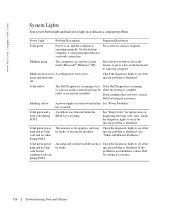
...identified. On the desktop computer, a solid green light indicates a network connection. Blinks green several A configuration error exists. Solid yellow The Dell Diagnostics is running a test, If the Dell Diagnostics is running,... locks up during POST A problem was detected while the BIOS was executing. www.dell.com | support.dell.com System Lights Your power button light and hard-drive ...may indicate a computer problem. specific problem is in a power-saving mode (Microsoft® Windows® XP). Press the power button, move the mouse, or press a key on diagnosing the ...
...identified. On the desktop computer, a solid green light indicates a network connection. Blinks green several A configuration error exists. Solid yellow The Dell Diagnostics is running a test, If the Dell Diagnostics is running,... locks up during POST A problem was detected while the BIOS was executing. www.dell.com | support.dell.com System Lights Your power button light and hard-drive ...may indicate a computer problem. specific problem is in a power-saving mode (Microsoft® Windows® XP). Press the power button, move the mouse, or press a key on diagnosing the ...

User Guide
Page 317
...diagnostic lights are not lit after the computer successfully boots to the operating system. the computer is in the Product Information Guide. Run the BIOS Recovery utility, wait for recovery completion, and then restart the computer. Diagnostic Lights CAUTION: Before you troubleshoot a problem, your computer has...codes on the lights change as the boot process completes. The diagnostic lights can be off " condition, or a possible pre-BIOS failure has occurred. When the computer starts normally, the patterns or codes on the lights change as the boot process completes. ...
...diagnostic lights are not lit after the computer successfully boots to the operating system. the computer is in the Product Information Guide. Run the BIOS Recovery utility, wait for recovery completion, and then restart the computer. Diagnostic Lights CAUTION: Before you troubleshoot a problem, your computer has...codes on the lights change as the boot process completes. The diagnostic lights can be off " condition, or a possible pre-BIOS failure has occurred. When the computer starts normally, the patterns or codes on the lights change as the boot process completes. ...

User Guide
Page 320
...3-3-1 3-3-2 3-3-4 3-4-1 3-4-2 3-4-3 4-2-1 4-2-2 4-2-3 4-2-4 4-3-1 4-3-3 4-3-4 4-4-1 4-4-2 4-4-3 Cause Microprocessor register failure NVRAM read/write failure ROM BIOS checksum failure Programmable interval timer failure DMA initialization failure DMA page register read/write failure Video Memory test failure Memory not being properly identified or...Memory test failure Screen initialization failure Screen retrace failure Search for technical assistance. www.dell.com | support.dell.com 3 Contact Dell for video ROM failure No timer tick Shutdown failure Gate A20 failure Unexpected interrupt in...
...3-3-1 3-3-2 3-3-4 3-4-1 3-4-2 3-4-3 4-2-1 4-2-2 4-2-3 4-2-4 4-3-1 4-3-3 4-3-4 4-4-1 4-4-2 4-4-3 Cause Microprocessor register failure NVRAM read/write failure ROM BIOS checksum failure Programmable interval timer failure DMA initialization failure DMA page register read/write failure Video Memory test failure Memory not being properly identified or...Memory test failure Screen initialization failure Screen retrace failure Search for technical assistance. www.dell.com | support.dell.com 3 Contact Dell for video ROM failure No timer tick Shutdown failure Gate A20 failure Unexpected interrupt in...


