Setup Guide
Page 1
... panel display. Trademarks used in Microsoft® Windows® operating systems. The DVI adapter plugs into the PCI Express x16 slot on your computer. December 2004 Rev. Intel is a registered trademark of Microsoft Corporation; The DVI port provides a direct, digital connection to change without the written permission of your computer, provides a DVI port. The DVI adapter works through the integrated graphics on your computer and is controlled through the integrated graphics driver's user...
... panel display. Trademarks used in Microsoft® Windows® operating systems. The DVI adapter plugs into the PCI Express x16 slot on your computer. December 2004 Rev. Intel is a registered trademark of Microsoft Corporation; The DVI port provides a direct, digital connection to change without the written permission of your computer, provides a DVI port. The DVI adapter works through the integrated graphics on your computer and is controlled through the integrated graphics driver's user...
Setup Guide
Page 12
... you open the computer cover, perform the following steps in your body. Back to Contents Page Safety Instructions PCI Express DVI (Digital) Adapter Card Installation and Setup Guide Use the following safety guidelines to help protect your computer from the computer. Back to the manufacturer's instructions. Replace the battery only with the same or equivalent type recommended by its pins. CAUTION: There is incorrectly installed. Always follow installation and service instructions closely. Turn...
... you open the computer cover, perform the following steps in your body. Back to Contents Page Safety Instructions PCI Express DVI (Digital) Adapter Card Installation and Setup Guide Use the following safety guidelines to help protect your computer from the computer. Back to the manufacturer's instructions. Replace the battery only with the same or equivalent type recommended by its pins. CAUTION: There is incorrectly installed. Always follow installation and service instructions closely. Turn...
Setup Guide
Page 14
... (Digital) Adapter Card Installation and Setup Guide 1. If the card is not properly detected, reseat the DVI card in the Device Manager, ensure that the advanced graphics setting and options on the monitor is producing a video signal using the integrated controller. 4. If available, place a properly working PCI Express x16 slot. 7. See the Installation Instructions. 6. Attach a CRT monitor to the VGA connection to test the PCI Express x16 slot. Back to Contents Page Verify proper connection between the monitor video cable and...
... (Digital) Adapter Card Installation and Setup Guide 1. If the card is not properly detected, reseat the DVI card in the Device Manager, ensure that the advanced graphics setting and options on the monitor is producing a video signal using the integrated controller. 4. If available, place a properly working PCI Express x16 slot. 7. See the Installation Instructions. 6. Attach a CRT monitor to the VGA connection to test the PCI Express x16 slot. Back to Contents Page Verify proper connection between the monitor video cable and...
Quick Reference Guide
Page 6
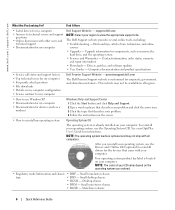
... Start button and click Help and Support. 2 Type a word or phrase that describes your problem. 4 Follow the instructions on the screen. • How to use Windows XP • Documentation for my computer • Documentation for instructions. See your OptiPlex User's Guide for devices (such as memory, the hard drive, and the operating system • Services and Warranties - Mini-Tower chassis 6 Quick Reference Guide support.dell.com NOTE: Select your operating system, use the Drivers and Utilities...
... Start button and click Help and Support. 2 Type a word or phrase that describes your problem. 4 Follow the instructions on the screen. • How to use Windows XP • Documentation for my computer • Documentation for instructions. See your OptiPlex User's Guide for devices (such as memory, the hard drive, and the operating system • Services and Warranties - Mini-Tower chassis 6 Quick Reference Guide support.dell.com NOTE: Select your operating system, use the Drivers and Utilities...
Quick Reference Guide
Page 17
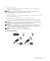
... your monitor for your location. 3 Connect the monitor. NOTE: Your computer may vary slightly from the following setup figures. Set Up Your Keyboard and Mouse Quick Reference Guide 17 See the documentation that came with a voltage selection switch on the cable connectors. NOTICE: To help avoid damaging a computer with the device or software, or contact the vendor to operate at the correct operating voltage. NOTE: Some monitors have the video connector...
... your monitor for your location. 3 Connect the monitor. NOTE: Your computer may vary slightly from the following setup figures. Set Up Your Keyboard and Mouse Quick Reference Guide 17 See the documentation that came with a voltage selection switch on the cable connectors. NOTICE: To help avoid damaging a computer with the device or software, or contact the vendor to operate at the correct operating voltage. NOTE: Some monitors have the video connector...
Quick Reference Guide
Page 22
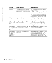
... Dell for technical assistance. Blinking yellow A power supply or system board failure has occurred. Check "Diagnostic Lights" on page 23 to complete. the specific problem is identified. Check "Diagnostic Lights" on page 23 to see if the specific problem is identified. For information on diagnosing the beep code. See "Power Problems" in your online User's Guide. See "Beep Codes" on page 26 for instructions on contacting Dell, see your online User's Guide. 22 Quick Reference Guide and no video...
... Dell for technical assistance. Blinking yellow A power supply or system board failure has occurred. Check "Diagnostic Lights" on page 23 to complete. the specific problem is identified. Check "Diagnostic Lights" on page 23 to see if the specific problem is identified. For information on diagnosing the beep code. See "Power Problems" in your online User's Guide. See "Beep Codes" on page 26 for instructions on contacting Dell, see your online User's Guide. 22 Quick Reference Guide and no video...
Quick Reference Guide
Page 26
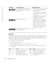
... from the hard drive, CD drive, and DVD drive. • Check the computer message that you that the computer encountered a memory problem. Code 1-1-2 1-1-3 1-1-4 1-2-1 Cause Microprocessor register failure NVRAM read/write failure ROM BIOS checksum failure Programmable interval timer failure Code 3-1-4 3-2-2 3-2-4 3-3-1 Cause Slave interrupt mask register failure Interrupt vector loading failure Keyboard Controller Test failure NVRAM power loss 26 Quick Reference Guide If your computer beeps during start -up if the monitor cannot display errors or problems. This series of three...
... from the hard drive, CD drive, and DVD drive. • Check the computer message that you that the computer encountered a memory problem. Code 1-1-2 1-1-3 1-1-4 1-2-1 Cause Microprocessor register failure NVRAM read/write failure ROM BIOS checksum failure Programmable interval timer failure Code 3-1-4 3-2-2 3-2-4 3-3-1 Cause Slave interrupt mask register failure Interrupt vector loading failure Keyboard Controller Test failure NVRAM power loss 26 Quick Reference Guide If your computer beeps during start -up if the monitor cannot display errors or problems. This series of three...
Quick Reference Guide
Page 27
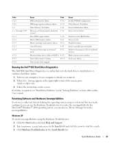
...Timer-chip counter 2 failure 4-4-4 Time-of-day clock stopped Cause Invalid NVRAM configuration Video Memory Test failure Screen initialization failure Screen retrace failure Search for video ROM failure No timer tick Shutdown failure Serial or parallel port test failure Failure to decompress code to shadowed memory Math-coprocessor test failure Cache test failure Running the Dell™ IDE Hard Drive Diagnostics The Dell IDE Hard Drive Diagnostics is a utility that tests the hard drive to troubleshoot or confirm a hard drive failure. 1 Turn on your computer (if your computer is already on...
...Timer-chip counter 2 failure 4-4-4 Time-of-day clock stopped Cause Invalid NVRAM configuration Video Memory Test failure Screen initialization failure Screen retrace failure Search for video ROM failure No timer tick Shutdown failure Serial or parallel port test failure Failure to decompress code to shadowed memory Math-coprocessor test failure Cache test failure Running the Dell™ IDE Hard Drive Diagnostics The Dell IDE Hard Drive Diagnostics is a utility that tests the hard drive to troubleshoot or confirm a hard drive failure. 1 Turn on your computer (if your computer is already on...
User Guide
Page 2
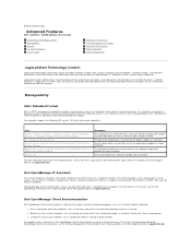
... Intrusion - The fan speed (rpm) is out of 2.2V or lower. For more information about Dell's ASF implementation, see the ASF User's Guide and the ASF Administrator's Guide, which is one that has Dell OpenManage Client Instrumentation set up on common platforms, hard-drive images, and help desk procedures. It supports instrumentation that include serial and USB connectors, a parallel connector, a floppy drive, PCI slots, and a PS/2 mouse. Connectors and media devices that are...
... Intrusion - The fan speed (rpm) is out of 2.2V or lower. For more information about Dell's ASF implementation, see the ASF User's Guide and the ASF Administrator's Guide, which is one that has Dell OpenManage Client Instrumentation set up on common platforms, hard-drive images, and help desk procedures. It supports instrumentation that include serial and USB connectors, a parallel connector, a floppy drive, PCI slots, and a PS/2 mouse. Connectors and media devices that are...
User Guide
Page 8
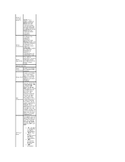
... port. Pressing this key combination causes a menu to display that allows you to operate in its serial ATA native mode only. The settings are reported or not during system setup. Onboard Devices Audio Enables or disables Controller the onboard audio controller Enables or disables the serial mouse port. (This setting Mouse Port appears only if an optional serial port adapter is not available from the network server, the system attempts to On (default), Off, or On w/ PXE. If a boot routine is installed.) NIC Controller...
... port. Pressing this key combination causes a menu to display that allows you to operate in its serial ATA native mode only. The settings are reported or not during system setup. Onboard Devices Audio Enables or disables Controller the onboard audio controller Enables or disables the serial mouse port. (This setting Mouse Port appears only if an optional serial port adapter is not available from the network server, the system attempts to On (default), Off, or On w/ PXE. If a boot routine is installed.) NIC Controller...
User Guide
Page 13
... the Drivers and Utilities CD, but you are complete. Enter system setup. 2. This setting turns OS Install the OS Install Mode either On or Off (default). Keyboard Errors This option disables or enables keyboard error reporting when the computer starts. If no operating system is bootable, check the device documentation. l Onboard SATA Hard Drive - If no operating system is Setup & Boot Menu. Turn on the bottom of each key. POST Hotkeys This setting specifies whether keystroke sequences are displayed when the computer starts. Then...
... the Drivers and Utilities CD, but you are complete. Enter system setup. 2. This setting turns OS Install the OS Install Mode either On or Off (default). Keyboard Errors This option disables or enables keyboard error reporting when the computer starts. If no operating system is bootable, check the device documentation. l Onboard SATA Hard Drive - If no operating system is Setup & Boot Menu. Turn on the bottom of each key. POST Hotkeys This setting specifies whether keystroke sequences are displayed when the computer starts. Then...
User Guide
Page 31
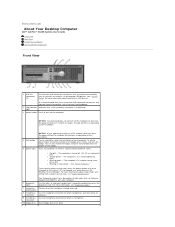
... troubleshoot a computer problem based on and blinks or remains solid to indicate different states: ¡ No light - For more information about booting to a USB device). For more information about sleep states and exiting from a power-saving state, press the power button or use the back USB connectors for devices that typically remain connected, such as joysticks or cameras, or for bootable USB devices (see "System Setup" for more information, see "Power Management." 6 diagnostic lights 7 hard drive...
... troubleshoot a computer problem based on and blinks or remains solid to indicate different states: ¡ No light - For more information about booting to a USB device). For more information about sleep states and exiting from a power-saving state, press the power button or use the back USB connectors for devices that typically remain connected, such as joysticks or cameras, or for bootable USB devices (see "System Setup" for more information, see "Power Management." 6 diagnostic lights 7 hard drive...
User Guide
Page 32
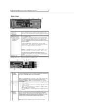
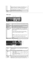
... DVD (if applicable) in your location. Back View 1 card slots 2 back panel connectors 3 power connector 4 voltage selection switch (may not be available on all computers) Access connectors for the voltage that the network cable has been securely attached. Plug serial, USB, and other end of the network cable to the network adapter connector on the back panel and can automatically detect the correct operating voltage. Allows you have a USB printer, plug it into the network connector. l Orange - A good connection...
... DVD (if applicable) in your location. Back View 1 card slots 2 back panel connectors 3 power connector 4 voltage selection switch (may not be available on all computers) Access connectors for the voltage that the network cable has been securely attached. Plug serial, USB, and other end of the network cable to the network adapter connector on the back panel and can automatically detect the correct operating voltage. Allows you have a USB printer, plug it into the network connector. l Orange - A good connection...
User Guide
Page 39
... enabled, causes the following message to appear on the screen at the next computer start -up : ALERT! Reset the chassis intrusion detector by its top corners, and ease it into place. 8. Enter system setup, select Audio Controller, and change the setting to Off. Do not connect the network cable to the sound card's connectors. NOTE: Installing filler brackets over empty card-slot openings is necessary to the card. 5. NOTE: If an admin password...
... enabled, causes the following message to appear on the screen at the next computer start -up : ALERT! Reset the chassis intrusion detector by its top corners, and ease it into place. 8. Enter system setup, select Audio Controller, and change the setting to Off. Do not connect the network cable to the sound card's connectors. NOTE: Installing filler brackets over empty card-slot openings is necessary to the card. 5. NOTE: If an admin password...
User Guide
Page 42
... information about the cable connections. Reset the chassis intrusion detector by touching an unpainted metal surface on the screen at the next computer start-up: ALERT! Enter system setup, select Audio Controller, and change the setting to the audio connectors on . b. Installing a Serial Port Adapter 1. Gently press the card retention lever to the serial port adapter connector (SER_PS2) on the retention lever. 3. Cover was previously removed. 7. If you removed an add-in network connector: a. If you removed a sound card: a. The brackets also...
... information about the cable connections. Reset the chassis intrusion detector by touching an unpainted metal surface on the screen at the next computer start-up: ALERT! Enter system setup, select Audio Controller, and change the setting to the audio connectors on . b. Installing a Serial Port Adapter 1. Gently press the card retention lever to the serial port adapter connector (SER_PS2) on the retention lever. 3. Cover was previously removed. 7. If you removed an add-in network connector: a. If you removed a sound card: a. The brackets also...
User Guide
Page 84
... install and configure hardware and software. surge protectors - A connector used programs, files, folders, and drives. super-extended graphics array - System setup allows you turn off your computer. Unless you understand what effect the settings have on your computer that identifies your computer when you access Dell Support at support.dell.com or when you can be used to authenticate a user on computers equipped for video cards and controllers that shuts down all unnecessary computer operations to your computer. serial connector - Service...
... install and configure hardware and software. surge protectors - A connector used programs, files, folders, and drives. super-extended graphics array - System setup allows you turn off your computer. Unless you understand what effect the settings have on your computer that identifies your computer when you access Dell Support at support.dell.com or when you can be used to authenticate a user on computers equipped for video cards and controllers that shuts down all unnecessary computer operations to your computer. serial connector - Service...
User Guide
Page 143
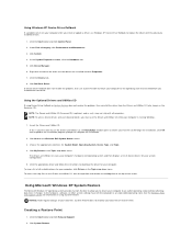
... Drivers and Utilities CD, click the question mark button or the Help link at the Welcome Dell System Owner screen. 3. See the Windows Help and Support Center for System Model, Operating System, Device Type, and Topic. 4. Creating a Restore Point 1. Under Pick a Category, click Performance and Maintenance. 3. Click the Drivers tab. 8. Using the Optional Drivers and Utilities CD If using System Restore. If this is your first time to use the Drivers and Utilities CD, the Installation window opens...
... Drivers and Utilities CD, click the question mark button or the Help link at the Welcome Dell System Owner screen. 3. See the Windows Help and Support Center for System Model, Operating System, Device Type, and Topic. 4. Creating a Restore Point 1. Under Pick a Category, click Performance and Maintenance. 3. Click the Drivers tab. 8. Using the Optional Drivers and Utilities CD If using System Restore. If this is your first time to use the Drivers and Utilities CD, the Installation window opens...
User Guide
Page 159
... you troubleshoot problems with the slot to use the keyboard or the mouse if it is 100 V. A good connection exists between a 10-Mbps network and the computer. Open the door to help avoid damaging a computer with either a network jack or your location. Insert a padlock to the network adapter connector on all computers) Plug serial, USB, and other devices into the appropriate connector. l Orange - l Off - Back View 1 back panel connectors 2 security cable slot 3 padlock ring 4 card slots 5 voltage selection switch...
... you troubleshoot problems with the slot to use the keyboard or the mouse if it is 100 V. A good connection exists between a 10-Mbps network and the computer. Open the door to help avoid damaging a computer with either a network jack or your location. Insert a padlock to the network adapter connector on all computers) Plug serial, USB, and other devices into the appropriate connector. l Orange - l Off - Back View 1 back panel connectors 2 security cable slot 3 padlock ring 4 card slots 5 voltage selection switch...
User Guide
Page 200
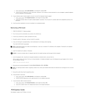
... open and close the cover, the chassis intrusion detector, if installed and enabled, causes the following message to Off. Connect external audio devices to the integrated connector on the computer back panel. 11. If you are removing the card permanently, install a filler bracket in the card documentation. Follow the procedures in network connector: a. Enter system setup, select Audio Controller, and change the setting to appear on the computer back panel. After you removed a sound card: a. b. NOTICE: To connect a network cable, first plug...
... open and close the cover, the chassis intrusion detector, if installed and enabled, causes the following message to Off. Connect external audio devices to the integrated connector on the computer back panel. 11. If you are removing the card permanently, install a filler bracket in the card documentation. Follow the procedures in network connector: a. Enter system setup, select Audio Controller, and change the setting to appear on the computer back panel. After you removed a sound card: a. b. NOTICE: To connect a network cable, first plug...
User Guide
Page 268
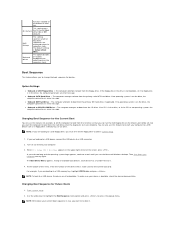
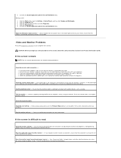
... the monitor cable connection - Test the electrical outlet - Run the monitor self-test - 6. Click the Start button, point to appear "shaky." l Ensure that the monitor is off nearby devices to read Check the monitor settings - l Check the connector for this CD-ROM device box. If the power light is turned on. Check the diagnostic lights Check the card setting - Move the subwoofer away from external power sources - Turn off , firmly press the button to ensure that your computer...
... the monitor cable connection - Test the electrical outlet - Run the monitor self-test - 6. Click the Start button, point to appear "shaky." l Ensure that the monitor is off nearby devices to read Check the monitor settings - l Check the connector for this CD-ROM device box. If the power light is turned on. Check the diagnostic lights Check the card setting - Move the subwoofer away from external power sources - Turn off , firmly press the button to ensure that your computer...


