

Technical Guide
Page 17
... system hard drives. 4.11.4 Trusted Platform Management (TPM) The TPM generates/stores keys, protects/authenticates passwords, and creates/stores digital certificates. There are different planar PWA part numbers to disable the power button function. 4.11.6 Intrusion Alert A switch mounted on the control panel or set up a system password. 13 DELL This mode includes the option to ESM. China TPM (TCM) is enabled through a BIOS option and uses HMAC-SHA1-160 for a plug-in Windows Server...
... system hard drives. 4.11.4 Trusted Platform Management (TPM) The TPM generates/stores keys, protects/authenticates passwords, and creates/stores digital certificates. There are different planar PWA part numbers to disable the power button function. 4.11.6 Intrusion Alert A switch mounted on the control panel or set up a system password. 13 DELL This mode includes the option to ESM. China TPM (TCM) is enabled through a BIOS option and uses HMAC-SHA1-160 for a plug-in Windows Server...

Technical Guide
Page 33
...) support • CPU Turbo Mode support • PCI 2.3 compliant • Plug n' Play 1.0a compliant • MP (Multiprocessor) 1.4 compliant • Boot from hard drive, optical drive, iSCSI drive, USB key, and SD card • ACPI support • Direct Media Interface (DMI) support • PXE and WOL support for on Motherboard (LOM) 12.1 Overview Two dual-port LAN controllers with support circuitry are TOE enabled, with optional iSCSI offload engine. 29 DELL This provides four LOM ports at end of the server.
...) support • CPU Turbo Mode support • PCI 2.3 compliant • Plug n' Play 1.0a compliant • MP (Multiprocessor) 1.4 compliant • Boot from hard drive, optical drive, iSCSI drive, USB key, and SD card • ACPI support • Direct Media Interface (DMI) support • PXE and WOL support for on Motherboard (LOM) 12.1 Overview Two dual-port LAN controllers with support circuitry are TOE enabled, with optional iSCSI offload engine. 29 DELL This provides four LOM ports at end of the server.
Technical Guide
Page 50
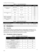
... Enterprise® 5.x (embedded) Support for remote locations. Embedded options require the optional SD card module to be installed. 19.2 Virtualization Options Supported Table 21. Solaris Operating System Installation - Accordingly, the T710 supports all major virtualization options available from Dell, including VMware, Citrix XenServer and Microsoft Hyper-V Server. Embedded options are available for VMware and Citrix XenServer. PowerEdge T710 Technical Guidebook Table 19. Linux Operating System Operating Systems Installation Factory Install Logo/Certification Red Hat...
... Enterprise® 5.x (embedded) Support for remote locations. Embedded options require the optional SD card module to be installed. 19.2 Virtualization Options Supported Table 21. Solaris Operating System Installation - Accordingly, the T710 supports all major virtualization options available from Dell, including VMware, Citrix XenServer and Microsoft Hyper-V Server. Embedded options are available for VMware and Citrix XenServer. PowerEdge T710 Technical Guidebook Table 19. Linux Operating System Operating Systems Installation Factory Install Logo/Certification Red Hat...
Technical Guide
Page 52
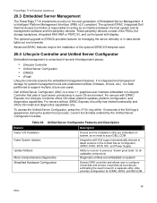
... Lifecycle Controller that aids in local server provisioning in data center lights-out environments. For servers with display. Current functionality enabled by the Unified Server Configurator includes: Table 22. The optional upgrade to iDRAC6 provides features for iDRAC, BIOS, and NIC/LOM. 48 DELL Dell Unified Server Configurator (USC) is comprised of Embedded Server Management. It is responsible for system-management tools and enablement utilities (firmware, drivers, etc.). The optional iDRAC (Integrated Dell Remote Access Controller) is flash partitioned to...
... Lifecycle Controller that aids in local server provisioning in data center lights-out environments. For servers with display. Current functionality enabled by the Unified Server Configurator includes: Table 22. The optional upgrade to iDRAC6 provides features for iDRAC, BIOS, and NIC/LOM. 48 DELL Dell Unified Server Configurator (USC) is comprised of Embedded Server Management. It is responsible for system-management tools and enablement utilities (firmware, drivers, etc.). The optional iDRAC (Integrated Dell Remote Access Controller) is flash partitioned to...

Owners Manual
Page 5
Using the System Password 72 Using the Setup Password 75 Embedded System Management 76 iDRAC Configuration Utility 77 Entering the iDRAC Configuration Utility 77 3 Installing System Components 79 Recommended Tools 79 Inside the System 79 Power Supplies 81 Removing a Power Supply 82 Installing a Power Supply 83 Removing a Power Supply Blank 83 Installing a Power Supply Blank 83 Front Bezel 84 Removing the Front Bezel 84 Installing the Front Bezel 85 Opening and Closing the System 85 Opening the System 85 Closing the System...
Using the System Password 72 Using the Setup Password 75 Embedded System Management 76 iDRAC Configuration Utility 77 Entering the iDRAC Configuration Utility 77 3 Installing System Components 79 Recommended Tools 79 Inside the System 79 Power Supplies 81 Removing a Power Supply 82 Installing a Power Supply 83 Removing a Power Supply Blank 83 Installing a Power Supply Blank 83 Front Bezel 84 Removing the Front Bezel 84 Installing the Front Bezel 85 Opening and Closing the System 85 Opening the System 85 Closing the System...
Owners Manual
Page 35
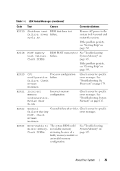
... invalid memory configuration. See "Troubleshooting System Memory" on page 179. Review User Guide. Check screen for specific error messages. POST. See "Troubleshooting the Processors" on page 167. configuration. If the problem persists, see "Getting Help" on Check DIMMs. page 167. Check screen for specific failure during error messages. Check screen for 10 seconds and restart the system. Remove AC power to The system BIOS could mirror memory. failure. E2023 BIOS Unable to the system for specific error...
... invalid memory configuration. See "Troubleshooting System Memory" on page 179. Review User Guide. Check screen for specific error messages. POST. See "Troubleshooting the Processors" on page 167. configuration. If the problem persists, see "Getting Help" on Check DIMMs. page 167. Check screen for specific failure during error messages. Check screen for 10 seconds and restart the system. Remove AC power to The system BIOS could mirror memory. failure. E2023 BIOS Unable to the system for specific error...
Owners Manual
Page 57
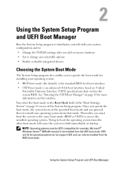
... boot mode (BIOS or UEFI) to access the installed operating system. Using the System Setup Program and UEFI Boot Manager Using the System Setup Program and UEFI Boot Manager Run the System Setup program to familiarize yourself with your system configuration and to: • Change the NVRAM settings after you add or remove hardware • Set or change user-selectable options • Enable or disable integrated devices Choosing the System Boot Mode The System Setup program also enables you to specify the boot mode for installing...
... boot mode (BIOS or UEFI) to access the installed operating system. Using the System Setup Program and UEFI Boot Manager Using the System Setup Program and UEFI Boot Manager Run the System Setup program to familiarize yourself with your system configuration and to: • Change the NVRAM settings after you add or remove hardware • Set or change user-selectable options • Enable or disable integrated devices Choosing the System Boot Mode The System Setup program also enables you to specify the boot mode for installing...
Owners Manual
Page 76
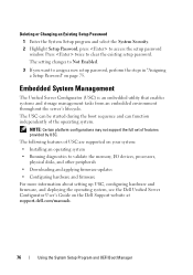
... Changing an Existing Setup Password 1 Enter the System Setup program and select the System Security. 2 Highlight Setup Password, press to validate the memory, I/O devices, processors, physical disks, and other peripherals • Downloading and applying firmware updates • Configuring hardware and firmware For more information about setting up USC, configuring hardware and firmware, and deploying the operating system, see the Dell Unified Server Configurator User's Guide on the Dell Support website at support.dell.com/manuals. 76 Using the System Setup Program and UEFI Boot Manager...
... Changing an Existing Setup Password 1 Enter the System Setup program and select the System Security. 2 Highlight Setup Password, press to validate the memory, I/O devices, processors, physical disks, and other peripherals • Downloading and applying firmware updates • Configuring hardware and firmware For more information about setting up USC, configuring hardware and firmware, and deploying the operating system, see the Dell Unified Server Configurator User's Guide on the Dell Support website at support.dell.com/manuals. 76 Using the System Setup Program and UEFI Boot Manager...

Owners Manual
Page 96
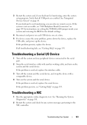
... safety instructions that accompanied the drive. Enable the tape drive's termination if it from 0 to the integrated storage controller card. If you are installing a SAS tape drive, you must configure the tape drive according to the documentation that all devices in a chain of the components inside the system. wide SCSI devices use IDs 0 to the SCSI controller. 2 Turn off the system, including any of devices (or sole device) connected...
... safety instructions that accompanied the drive. Enable the tape drive's termination if it from 0 to the integrated storage controller card. If you are installing a SAS tape drive, you must configure the tape drive according to the documentation that all devices in a chain of the components inside the system. wide SCSI devices use IDs 0 to the SCSI controller. 2 Turn off the system, including any of devices (or sole device) connected...

Owners Manual
Page 135
... switch cable to the electrical outlet. 11 Turn on a flat surface. 3 Open the system. Before you begin this procedure, review the safety instructions that the slots in the carrier are authorized to remove the system cover and access any of the components inside of the system and slide the carrier up and out of the securing tabs. See "Installing an Integrated Storage Controller Card...
... switch cable to the electrical outlet. 11 Turn on a flat surface. 3 Open the system. Before you begin this procedure, review the safety instructions that the slots in the carrier are authorized to remove the system cover and access any of the components inside of the system and slide the carrier up and out of the securing tabs. See "Installing an Integrated Storage Controller Card...

Owners Manual
Page 160
... the problem is resolved, replace the faulty keyboard/mouse. Troubleshooting the Video Subsystem 1 Check the system and power connections to the monitor. 2 Check the video interface cabling from the system. 160 Troubleshooting Your System See "Running the System Diagnostics" on page 193 Troubleshooting a USB Device 1 Use the following steps to video hardware. If the tests run successfully, the problem is resolved, restart the system, enter the System Setup program, and check if the nonfunctioning USB ports are enabled...
... the problem is resolved, replace the faulty keyboard/mouse. Troubleshooting the Video Subsystem 1 Check the system and power connections to the monitor. 2 Check the video interface cabling from the system. 160 Troubleshooting Your System See "Running the System Diagnostics" on page 193 Troubleshooting a USB Device 1 Use the following steps to video hardware. If the tests run successfully, the problem is resolved, restart the system, enter the System Setup program, and check if the nonfunctioning USB ports are enabled...
Owners Manual
Page 161
... same problem, power down the device, replace the USB cable, and power up the device. If your system and restoring the BIOS to the NIC controller. If the problem persists, replace the device. If the problem is functioning, enter the system setup program. Verify that all troubleshooting fails, see "Getting Help" on the system and the serial device. See "Integrated Devices Screen" on the system and the serial device. Troubleshooting a NIC 1 Run the appropriate online diagnostic test. See "Running...
... same problem, power down the device, replace the USB cable, and power up the device. If your system and restoring the BIOS to the NIC controller. If the problem persists, replace the device. If the problem is functioning, enter the system setup program. Verify that all troubleshooting fails, see "Getting Help" on the system and the serial device. See "Integrated Devices Screen" on the system and the serial device. Troubleshooting a NIC 1 Run the appropriate online diagnostic test. See "Running...

Owners Manual
Page 162
... light, check all network cables are authorized to the same data transmission speed. See "Opening the System" on the switch or hub. See "NIC Indicator Codes" on page 193. See the NIC's documentation. • Change the auto negotiation setting, if possible. • Use another connector on page 85. 162 Troubleshooting Your System Troubleshooting a Wet System WARNING: Only trained service technicians are of the components inside...
... light, check all network cables are authorized to the same data transmission speed. See "Opening the System" on the switch or hub. See "NIC Indicator Codes" on page 193. See the NIC's documentation. • Change the auto negotiation setting, if possible. • Use another connector on page 85. 162 Troubleshooting Your System Troubleshooting a Wet System WARNING: Only trained service technicians are of the components inside...
Owners Manual
Page 165
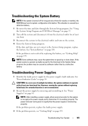
... it is working properly. The power indicator turns green to operate with at least one functional fan. Troubleshooting Your System 165 Troubleshooting Power Supplies 1 Identify the faulty power supply by a defective battery. 1 Re-enter the time and date through the System Setup program. If the problem is not resolved by removing and reinstalling it. See "Power Supplies" on page 57. 2 Turn off for long periods of multiple fan failure, the system...
... it is working properly. The power indicator turns green to operate with at least one functional fan. Troubleshooting Your System 165 Troubleshooting Power Supplies 1 Identify the faulty power supply by a defective battery. 1 Re-enter the time and date through the System Setup program. If the problem is not resolved by removing and reinstalling it. See "Power Supplies" on page 57. 2 Turn off for long periods of multiple fan failure, the system...

Owners Manual
Page 175
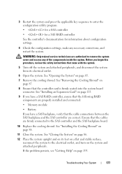
... operating system and the controller. 1 Run the appropriate online diagnostic test. b Open the system. c Verify that the cable connections between the hard drive(s) and the drive controller are correct and that the SAS or PERC controller is enabled. If the problem persists, see the documentation for information about configuration settings. See "Using Online Diagnostics" on page 193. See "Using the System Setup Program and UEFI Boot Manager" on page 86. Troubleshooting a Storage Controller NOTE: When troubleshooting...
... operating system and the controller. 1 Run the appropriate online diagnostic test. b Open the system. c Verify that the cable connections between the hard drive(s) and the drive controller are correct and that the SAS or PERC controller is enabled. If the problem persists, see the documentation for information about configuration settings. See "Using Online Diagnostics" on page 193. See "Using the System Setup Program and UEFI Boot Manager" on page 86. Troubleshooting a Storage Controller NOTE: When troubleshooting...

Owners Manual
Page 176
... "Installing an Integrated Storage Controller Card" on page 85. 7 Ensure that the controller card is enabled. WARNING: Only trained service technicians are firmly connected to the electrical outlet, and turn on page 193. See "Using the System Setup Program and UEFI Boot Manager" on the PERC card is properly seated. 9 Verify that the SAS or SAS RAID controller is firmly seated into the system board connector. 4 Check the configuration settings, make...
... "Installing an Integrated Storage Controller Card" on page 85. 7 Ensure that the controller card is enabled. WARNING: Only trained service technicians are firmly connected to the electrical outlet, and turn on page 193. See "Using the System Setup Program and UEFI Boot Manager" on the PERC card is properly seated. 9 Verify that the SAS or SAS RAID controller is firmly seated into the system board connector. 4 Check the configuration settings, make...
Owners Manual
Page 177
... cables are properly installed and connected: • Memory module • Battery If you begin this procedure, review the safety instructions that the cable connections between the SAS backplane and the SAS controller are authorized to enter the configuration utility program: • for a SAS controller • for a SAS RAID controller See the controller's documentation for information about configuration settings. 4 Check the configuration settings, make any of the components inside the system. See "Installing an Expansion Card...
... cables are properly installed and connected: • Memory module • Battery If you begin this procedure, review the safety instructions that the cable connections between the SAS backplane and the SAS controller are authorized to enter the configuration utility program: • for a SAS controller • for a SAS RAID controller See the controller's documentation for information about configuration settings. 4 Check the configuration settings, make any of the components inside the system. See "Installing an Expansion Card...

Owners Manual
Page 201
... setting features such as the processor(s), RAM, controllers for technical support. A BIOS-based program that allows a network manager to the system BIOS and then display an error message on the system used . Serial Advanced Technology Attachment. service tag - Because the System Setup program is most of space used to connect a modem to configure your system's integral components, such as password protection. Synchronous dynamic random-access memory. SCSI - Allows hard drives to report errors and failures to remotely monitor...
... setting features such as the processor(s), RAM, controllers for technical support. A BIOS-based program that allows a network manager to the system BIOS and then display an error message on the system used . Serial Advanced Technology Attachment. service tag - Because the System Setup program is most of space used to connect a modem to configure your system's integral components, such as password protection. Synchronous dynamic random-access memory. SCSI - Allows hard drives to report errors and failures to remotely monitor...

Owners Manual
Page 202
... electrical failure. TOE - A battery-powered unit that provides (in the cable. Universal Serial Bus. USB memory key - See memory key. Volt(s) alternating current. video adapter - The logical circuitry that automatically supplies power to enable or disable the termination on these devices by changing jumper or switch settings on a network hub or switch used to prevent reflections and spurious signals in combination with the appropriate video drivers and monitor capabilities). Most VGA and SVGA video adapters include memory chips in a series, you must install...
... electrical failure. TOE - A battery-powered unit that provides (in the cable. Universal Serial Bus. USB memory key - See memory key. Volt(s) alternating current. video adapter - The logical circuitry that automatically supplies power to enable or disable the termination on these devices by changing jumper or switch settings on a network hub or switch used to prevent reflections and spurious signals in combination with the appropriate video drivers and monitor capabilities). Most VGA and SVGA video adapters include memory chips in a series, you must install...

Owners Manual
Page 208
...175 support contacting Dell, 193 system cooling troubleshooting, 166 system features accessing, 11 system messages, 39 system password, 72 system setup options, 59 system setup program CPU options, 62 entering, 58 Index 208 power supplies indicators, 24 installing, 83 removing, 82 troubleshooting, 165 power supply blank, 83 processor installing, 110 removing, 107 upgrades, 107 R RAID battery installing, 128 removing, 127 removing battery (RAID), 127 control panel assembly, 145 cooling fans, 136 expansion cards, 118 hard drive blank, 90-91 hard drive from a drive carrier, 92 hard drives, 90...
...175 support contacting Dell, 193 system cooling troubleshooting, 166 system features accessing, 11 system messages, 39 system password, 72 system setup options, 59 system setup program CPU options, 62 entering, 58 Index 208 power supplies indicators, 24 installing, 83 removing, 82 troubleshooting, 165 power supply blank, 83 processor installing, 110 removing, 107 upgrades, 107 R RAID battery installing, 128 removing, 127 removing battery (RAID), 127 control panel assembly, 145 cooling fans, 136 expansion cards, 118 hard drive blank, 90-91 hard drive from a drive carrier, 92 hard drives, 90...


