Quick Reference Guide
Page 28
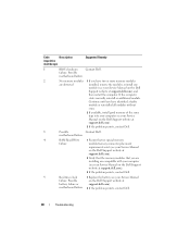
.... Code Description (repetitive short beeps) Suggested Remedy 1 BIOS checksum Contact Dell. Possible motherboard failure. 2 No memory modules 1 If you have two or more memory modules are compatible with your computer (see your Service Manual on the Dell Support website at support.dell.com). 3 If the problem persists, contact Dell. 5 Real time clock 1 Replace the battery...
.... Code Description (repetitive short beeps) Suggested Remedy 1 BIOS checksum Contact Dell. Possible motherboard failure. 2 No memory modules 1 If you have two or more memory modules are compatible with your computer (see your Service Manual on the Dell Support website at support.dell.com). 3 If the problem persists, contact Dell. 5 Real time clock 1 Replace the battery...
Quick Reference Guide
Page 29
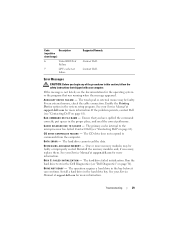
...L E M E M O R Y - One or more information. Install a hard drive in the system setup program. Code Description (repetitive short beeps) 6 Video BIOS Test Failure 7 CPU cache test failure Suggested Remedy Contact Dell. Contact Dell. Enable the Pointing Device option in the hard drive bay. D E C R E A S I N G A V A I L U R E - If ... D C O M M A N D O R FILE N A M E - Ensure that you begin any of the procedures in the bay before it can continue. Contact Dell (see the documentation for more information. C D D R I V E C O N T R O L L E R F A I L U R E - The...
...L E M E M O R Y - One or more information. Install a hard drive in the system setup program. Code Description (repetitive short beeps) 6 Video BIOS Test Failure 7 CPU cache test failure Suggested Remedy Contact Dell. Contact Dell. Enable the Pointing Device option in the hard drive bay. D E C R E A S I N G A V A I L U R E - If ... D C O M M A N D O R FILE N A M E - Ensure that you begin any of the procedures in the bay before it can continue. Contact Dell (see the documentation for more information. C D D R I V E C O N T R O L L E R F A I L U R E - The...
Quick Reference Guide
Page 35
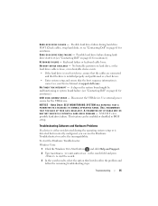
...the Hardware Troubleshooter: Windows Vista: 1 Click the Windows Vista Start button , and click Help and Support. 2 Type hardware troubleshooter in BIOS setup. Possible hard drive failure during hard drive POST. USB OVER CURRENT ERROR - NOTICE - Troubleshooting 35 Keyboard failure or keyboard cable ...loose. A chip on page 61 for assistance. DELL RECOMMENDS THAT YOU BACK UP YOUR DATA REGULARLY. HA R D -DISK DRIVE FAILURE - KEYBOARD FAILURE - No bootable partition on page 61...
...the Hardware Troubleshooter: Windows Vista: 1 Click the Windows Vista Start button , and click Help and Support. 2 Type hardware troubleshooter in BIOS setup. Possible hard drive failure during hard drive POST. USB OVER CURRENT ERROR - NOTICE - Troubleshooting 35 Keyboard failure or keyboard cable ...loose. A chip on page 61 for assistance. DELL RECOMMENDS THAT YOU BACK UP YOUR DATA REGULARLY. HA R D -DISK DRIVE FAILURE - KEYBOARD FAILURE - No bootable partition on page 61...
Technical Guide
Page 63
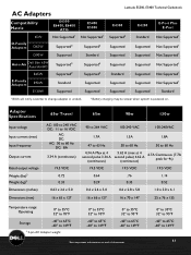
... D65W Supported2 D90W Supported E5400 E5500 Not Supported1 Supported2 Standard Latitude E5500, E5400 Technical Guidebook E4300 Supported2 Supported Supported E4200 E-Port Plus E-Port Standard Not Supported1 Supported Supported Not Supported1 Not Supported1 Auto-Air Dell Slim 65W Auto/Air/...AC E-Family Adapters E65W E90W E130W Supported2 Supported2 Standard Supported Supported2 Supported2 Supported Supported Supported Standard Supported Supported Supported Not Supported1 Supported Supported Not Supported1 Not Supported1 Supported Standard 1 BIOS ...
... D65W Supported2 D90W Supported E5400 E5500 Not Supported1 Supported2 Standard Latitude E5500, E5400 Technical Guidebook E4300 Supported2 Supported Supported E4200 E-Port Plus E-Port Standard Not Supported1 Supported Supported Not Supported1 Not Supported1 Auto-Air Dell Slim 65W Auto/Air/...AC E-Family Adapters E65W E90W E130W Supported2 Supported2 Standard Supported Supported2 Supported2 Supported Supported Supported Standard Supported Supported Supported Not Supported1 Supported Supported Not Supported1 Not Supported1 Supported Standard 1 BIOS ...
Service Manual
Page 1
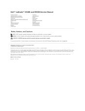
...Intel and Celeron are either trademarks or registered trademarks of your computer. Dell Inc. A00 Dell™ Latitude™ E5400 and E5500 Service Manual Troubleshooting Working on Your Computer Bottom of the ...I/O Card Speaker Assembly Coin-Cell Battery Flashing the BIOS Notes, Notices, and Cautions NOTE: A NOTE indicates important information that helps ...Core is strictly forbidden. Models PP32LA and PP32LB May 2008 Rev. Trademarks used by Bluetooth SIG, Inc., and is a trademark of Dell Inc. disclaims any proprietary interest in this text: Dell, Latitude, ExpressCharge, and the DELL...
...Intel and Celeron are either trademarks or registered trademarks of your computer. Dell Inc. A00 Dell™ Latitude™ E5400 and E5500 Service Manual Troubleshooting Working on Your Computer Bottom of the ...I/O Card Speaker Assembly Coin-Cell Battery Flashing the BIOS Notes, Notices, and Cautions NOTE: A NOTE indicates important information that helps ...Core is strictly forbidden. Models PP32LA and PP32LB May 2008 Rev. Trademarks used by Bluetooth SIG, Inc., and is a trademark of Dell Inc. disclaims any proprietary interest in this text: Dell, Latitude, ExpressCharge, and the DELL...
Service Manual
Page 4
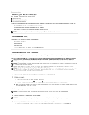
... require the following tools: l Small flat-blade screwdriver l Phillips screwdriver l Small plastic scribe l Flash BIOS update (see the Regulatory Compliance Homepage on www.dell.com at support.dell.com. NOTICE: When disconnecting a cable, pull on the cable's connector or on its edges, not ... such as a processor by its strain-relief loop, not on a card. Back to Contents Page Working on Your Computer Dell™ Latitude™ E5400 and E5500 Service Manual Recommended Tools Before Working on Your Computer After Working on Your Computer This document provides procedures for 4 seconds. 3....
... require the following tools: l Small flat-blade screwdriver l Phillips screwdriver l Small plastic scribe l Flash BIOS update (see the Regulatory Compliance Homepage on www.dell.com at support.dell.com. NOTICE: When disconnecting a cable, pull on the cable's connector or on its edges, not ... such as a processor by its strain-relief loop, not on a card. Back to Contents Page Working on Your Computer Dell™ Latitude™ E5400 and E5500 Service Manual Recommended Tools Before Working on Your Computer After Working on Your Computer This document provides procedures for 4 seconds. 3....
Service Manual
Page 6
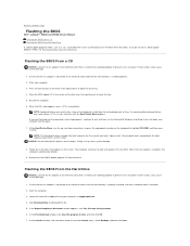
... push to the boot sequence specified in the center of power. Back to Contents Page Flashing the BIOS Dell™ Latitude™ E5400 and E5500 Service Manual Flashing the BIOS From a CD Flashing the BIOS From the Hard Drive If a BIOS-update program media, such as a CD, is attached. 2. Start your computer at the front of power...
... push to the boot sequence specified in the center of power. Back to Contents Page Flashing the BIOS Dell™ Latitude™ E5400 and E5500 Service Manual Flashing the BIOS From a CD Flashing the BIOS From the Hard Drive If a BIOS-update program media, such as a CD, is attached. 2. Start your computer at the front of power...

Service Manual
Page 7
Back to your desktop and is titled the same as the downloaded BIOS update file. 9. The file icon appears on the screen. The file downloads to Contents Page Double-click the file icon on the desktop and follow the instructions on your desktop. 8. Click Close if the Download Complete window appears.
Back to your desktop and is titled the same as the downloaded BIOS update file. 9. The file icon appears on the screen. The file downloads to Contents Page Double-click the file icon on the desktop and follow the instructions on your desktop. 8. Click Close if the Download Complete window appears.
Service Manual
Page 57
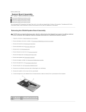
...battery connector (refer to Contents Page System Board Assembly Dell™ Latitude™ E5400 and E5500 Service Manual Removing the E5400 System Board Assembly Replacing the E5400 System Board Assembly Removing the E5500 System Board Assembly ...Replacing the E5500 System Board Assembly The system board's BIOS chip contains the Service Tag, which is also visible on a barcode label on the base of the computer. 1 E5400...
...battery connector (refer to Contents Page System Board Assembly Dell™ Latitude™ E5400 and E5500 Service Manual Removing the E5400 System Board Assembly Replacing the E5400 System Board Assembly Removing the E5500 System Board Assembly ...Replacing the E5500 System Board Assembly The system board's BIOS chip contains the Service Tag, which is also visible on a barcode label on the base of the computer. 1 E5400...
Service Manual
Page 58
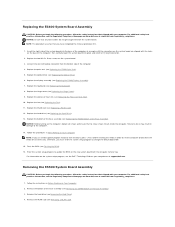
...that you begin the following procedure, follow the safety instructions that shipped with your computer or at : www.dell.com/regulatory_compliance. Replace the optical drive (see Replacing the E5400 Display Assembly). 7. Replace the display assembly (see Replacing the Optical Drive). 6. Replace the keyboard (see ...dell.com. Removing the E5500 System Board Assembly CAUTION: Before you use a BIOS update program media to flash the BIOS, press before inserting the media in damage to change the default boot order. 15. Remove the bottom of the base assembly (see Removing the E5400...
...that you begin the following procedure, follow the safety instructions that shipped with your computer or at : www.dell.com/regulatory_compliance. Replace the optical drive (see Replacing the E5400 Display Assembly). 7. Replace the display assembly (see Replacing the Optical Drive). 6. Replace the keyboard (see ...dell.com. Removing the E5500 System Board Assembly CAUTION: Before you use a BIOS update program media to flash the BIOS, press before inserting the media in damage to change the default boot order. 15. Remove the bottom of the base assembly (see Removing the E5400...
Service Manual
Page 60
...Drive). 13. Otherwise, you use a BIOS update program media to flash the BIOS, press before inserting the media in After Working on your computer or at support.dell.com. Replace the hard drive (see Replacing the Fan). 11. Back to update the BIOS on the new system board with the ...Service Tag. 9. Replace the bottom of the Base Assembly). 14. Flash the BIOS (see Replacing the E5500 Bottom of the base assembly (see Flashing the BIOS). 16. For information on the system setup program, see the Dell™ Technology Guide on Your Computer. NOTE: If you must enter the system...
...Drive). 13. Otherwise, you use a BIOS update program media to flash the BIOS, press before inserting the media in After Working on your computer or at support.dell.com. Replace the hard drive (see Replacing the Fan). 11. Back to update the BIOS on the new system board with the ...Service Tag. 9. Replace the bottom of the Base Assembly). 14. Flash the BIOS (see Replacing the E5500 Bottom of the base assembly (see Flashing the BIOS). 16. For information on the system setup program, see the Dell™ Technology Guide on Your Computer. NOTE: If you must enter the system...
Service Manual
Page 62
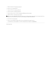
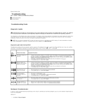
...then turn off ) of the Num Lock, Caps Lock, and Scroll Lock features. Back to Contents Page Troubleshooting Dell™ Latitude™ E5400 and E5500 Service Manual Troubleshooting Tools Solving Problems Troubleshooting Tools Diagnostic Lights CAUTION: Before you begin any installed graphics cards....the Num Lock light may remain on, depending on your BIOS settings. l If available, install working graphics card into your computer. l If the problem persists, contact Dell Support. l If the problem persists, contact Dell Support. If the computer malfunctions, however, you have ...
...then turn off ) of the Num Lock, Caps Lock, and Scroll Lock features. Back to Contents Page Troubleshooting Dell™ Latitude™ E5400 and E5500 Service Manual Troubleshooting Tools Solving Problems Troubleshooting Tools Diagnostic Lights CAUTION: Before you begin any installed graphics cards....the Num Lock light may remain on, depending on your BIOS settings. l If available, install working graphics card into your computer. l If the problem persists, contact Dell Support. l If the problem persists, contact Dell Support. If the computer malfunctions, however, you have ...


